Temperature control in plastics processing is not a background utility; it is a primary process variable that determines part quality, cycle time, and even the stability of your plantŌĆÖs power system. Whether you are running injection molding, extrusion, thermoforming, or highŌĆætemperature engineering resins, the way you heat and cool plastic ŌĆō and how you power those systems ŌĆō will decide if your lines run smoothly or constantly fight scrap and downtime.
From a power and reliability standpoint, temperature control units (TCUs), mold temperature controllers, and chillers are among the largest continuous electrical loads in a plastics plant. At the same time, sources such as Conair, Delta T Systems, and North Slope Chillers all underline that cooling and recovery can account for most of the cycle time for a single part, often around fourŌĆæfifths of the total molding time. When one system touches both your productivity and your electrical infrastructure this strongly, it deserves deliberate design.
This article walks through how plastics behave thermally, how modern temperature control systems manage that behavior, and how to specify and operate those systems for reliability, quality, and energy efficiency.
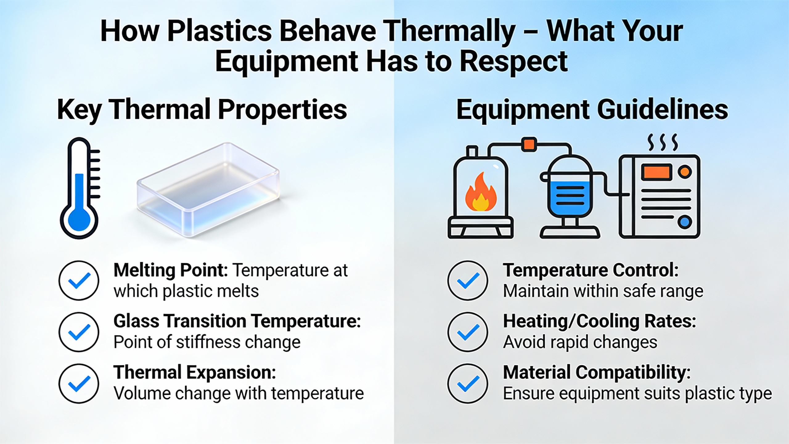
How Plastics Behave Thermally ŌĆō What Your Equipment Has to Respect
Before talking about chillers and TCUs, it is worth reviewing what the plastic itself does as temperature changes. A widely used plastics materials text from Brigham Young University ŌĆō Idaho describes several thermal behaviors that every processor must work around.
Low Thermal Conductivity and High Heat Capacity
Plastics conduct heat poorly compared with metals. Typical plastic thermal conductivity is roughly 0.03 to 0.06 Btu per hour per foot per degree Fahrenheit, while metals sit about three orders of magnitude higher, around 30 to 60 Btu per hour per foot per degree Fahrenheit. At the same time, many polymers have relatively high heat capacity, often about 0.4 to 0.9 Btu per pound per degree Fahrenheit, compared with roughly 0.1 to 0.3 for metals.
In practical terms, this combination means plastic parts heat and cool slowly and unevenly. Heat does not move quickly from the core of a part to the surface, so any cold or hot spot in the mold strongly imprints itself on the part. This is why cooling channels, turbulent flow, and carefully controlled mold temperatures are essential; the mold and coolant must compensate for the plasticŌĆÖs reluctance to move heat.
As a simple illustration, if you have a thick molded boss that is twice as thick as a nearby wall, the low conductivity of the polymer means that boss will retain heat much longer. Without localized cooling features such as baffles or thermal pins, it will become a persistent source of shrinkage and warpage even when the rest of the part looks fine.
Expansion, Shrinkage, and Mismatch with Metals
Thermal expansion is another critical property. The plastics textbook notes that typical linear coefficients of thermal expansion for polymers fall around 9 to 12 ├Ś 10Ōü╗ŌüĄ inch per inch per degree Fahrenheit. Common metals sit much lower, around 2 to 8 ├Ś 10Ōü╗ŌüĄ, and ceramics still lower.
This mismatch has two consequences. First, plastic parts will change size more with temperature than metal inserts or fasteners. If you mold around metal hardware and then run the part at elevated temperature, the plastic may expand more than the metal and loosen the joint. Second, molds must be dimensioned so that hot plastic fills a slightly oversized cavity and then shrinks as it cools to the target dimension; you cannot simply cut steel to final size and expect the part to match.
Ceramic or glass fillers reduce overall expansion by constraining chain motion. That is one reason filled engineering resins are attractive for highŌĆæprecision parts, but it also makes their processing windows narrower and their thermal behavior more sensitive to mold temperature control.
Glass Transition, HDT, and LongŌĆæTerm Temperature Limits
Polymers do not have a single ŌĆ£maximum temperatureŌĆØ; instead they pass through several transitions. The glass transition temperature, Tg, marks where amorphous regions of a polymer shift from rigid and glasslike to leathery or rubbery. Below Tg, chains are effectively locked; above Tg, coordinated motions of segments begin, and stiffness drops.
For structural parts, another practical metric is Heat Distortion Temperature (HDT), measured under load. In HDT testing, a standard specimen in a heated bath is loaded and the temperature at which it deflects by a set amount is recorded. HDT is widely used as an approximate maximum use temperature under mechanical load, but it is not a material constant; it depends on sample size and load and is usually below Tg. In real parts, longŌĆæterm creep under stress may require you to operate well below the published HDT to avoid distortion.
There are also longŌĆæterm endurance metrics. The UL temperature index (often called Relative Thermal Index or RTI) identifies the air temperature at which a material loses about half of a chosen property after 10,000 hours. This continuous use temperature is very different from a shortŌĆæterm excursion; powerŌĆæelectronicsŌĆæheavy applications or underŌĆæhood automotive parts care deeply about RTI.
Vicatt softening temperature, which measures when a needle penetrates a plastic specimen to a set depth under load, is another indicator of when surfaces will start to deform under modest stresses.
From a processing viewpoint, these transitions create a window. Melt and mold temperatures must be high enough that the polymer fills the mold fully and develops the desired crystallinity or amorphous structure, yet low enough that thermal degradation, excessive creep, or longŌĆæterm property loss do not occur. The job of thermal management is to keep the entire part inside that narrow window during heating, filling, packing, and cooling.
Time, Heat, and Creep
Creep ŌĆō the slow, timeŌĆædependent deformation of a polymer under load ŌĆō accelerates with temperature. The BYUŌĆæIdaho text emphasizes that creep decreases with higher crystallinity, more entanglement, bulky side groups, crosslinking, and stiff backbones, but even highŌĆæperformance resins will creep if held near their upper service temperature for long periods.
This is where process control intersects with reliability. Parts molded at too low a mold temperature can freeze in internal stresses; as they see heat and load in service, those stresses relax as creep and warpage. Parts molded at too high a temperature may suffer early softening or distortion when they see only moderate ambient temperatures later. Getting mold temperature right protects not only cosmetics and dimensions but longŌĆæterm mechanical performance.
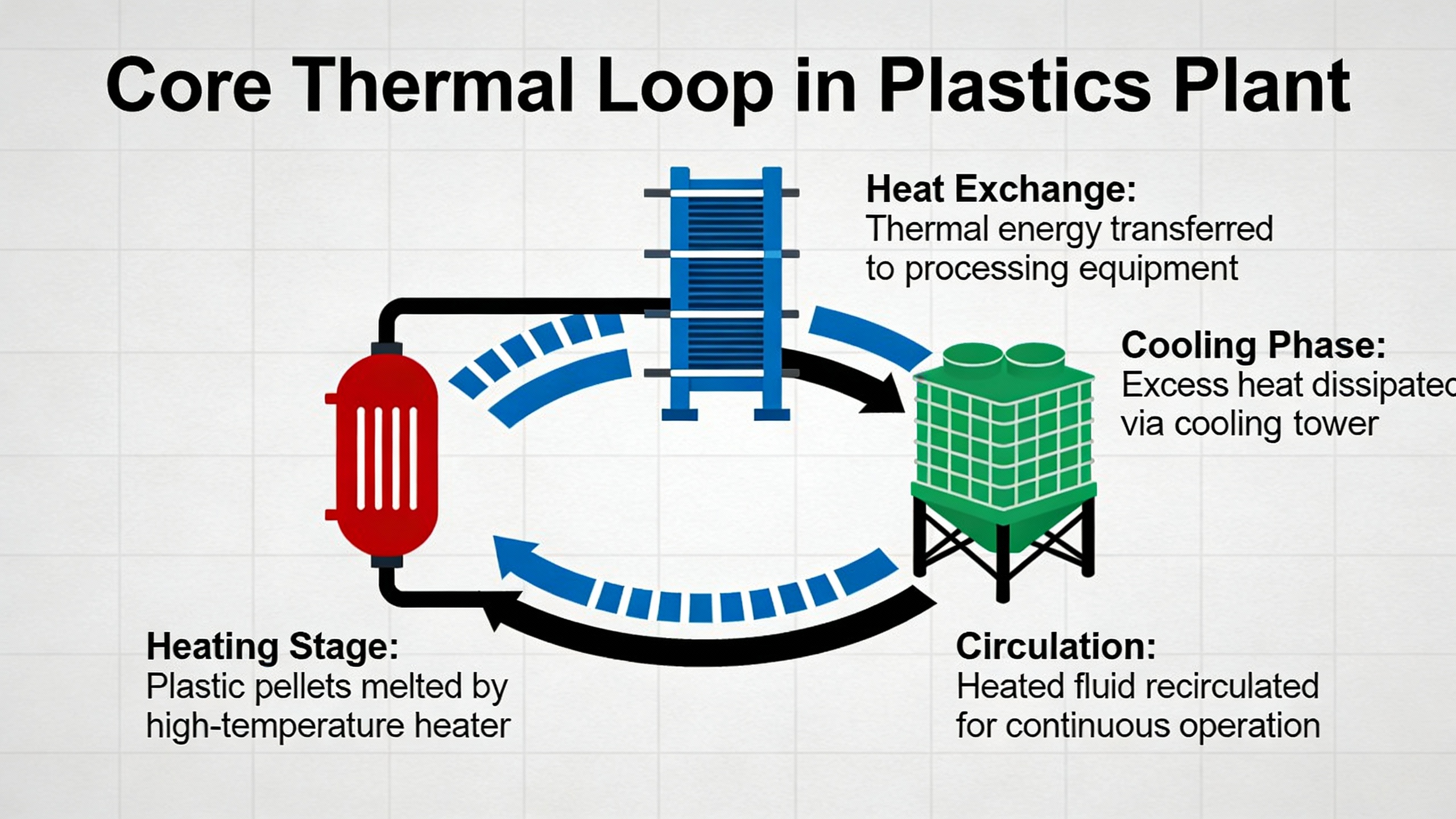
The Core Thermal Loop in a Plastics Plant
In most plastics operations, the thermal loop consists of the mold or die, a temperature control unit, a heatŌĆætransfer medium, and, for many installations, a central or dedicated chiller.
A temperature control unit, often generically called a Thermolator based on a longŌĆæstanding brand name, regulates mold or tooling temperature within a tight band. According to technical material from Conair, modern TCUs combine a pump, electric heater, cooling system, and controller in a mobile package. They circulate water or thermal oil through the mold, compare returning temperature to the setpoint, and either add heat or route heat to a cooling source.
Delta T Systems describes plastics temperature control systems that cover process temperatures from roughly ŌĆō10┬░F up to about 550┬░F. Their mold temperature controllers provide both heating and cooling, enabling fast preheat and coolŌĆædown cycles even for very large molds, and their packaged chillers maintain process temperature within about ┬▒0.5┬░F using advanced controls and variableŌĆæspeed compressors.
A separate chiller removes heat from the TCUŌĆÖs coolant loop and rejects it to ambient. North Slope Chillers and Thermal Care both emphasize that waterŌĆæcooled chillers with glycol mixtures provide much more effective and targeted heat removal than simple air cooling. AirŌĆæcooled systems can work for lowŌĆævolume jobs but tend to cool the entire space instead of the mold, which is slow and energy intensive.
Water, Pressurized Water, and Oil
Thermal equipment manufacturers such as REGLOPLAS highlight that the choice of heatŌĆætransfer medium is primarily driven by the required mold temperature.
A simplified view looks like this:
| Medium / System type | Approximate mold temperature band (┬░F) | Typical use |
| Water TCU (nonŌĆæpressurized) | Up to about 190┬░F | Commodity resins and many engineering plastics |
| Pressurized water TCU | About 190┬░F to about 480┬░F | HigherŌĆætemperature engineering resins and tooling |
| Oil TCU | Above roughly 480┬░F | Very highŌĆætemperature resins, specialized highŌĆætemp tooling |
| Process chillers (air or water) | Typically supply 40┬░F to 70┬░F coolant, sometimes warmer by design | Removal of waste heat from TCUs and molds |
REGLOPLAS notes that waterŌĆæbased systems are preferred wherever possible because water has better heatŌĆætransfer properties than oil and is more cost effective. They indicate that standard water cooling is practical up to around 90┬░C, about 190┬░F, and that pressurized water systems can push that upper limit to roughly 250┬░C, near 480┬░F. Above that, oil becomes the only viable heatŌĆætransfer fluid.
Conair adds that TCUs for commodity polymers often control molds around 70┬░F to 80┬░F, while engineering plastics like nylon or polycarbonate may require mold temperatures between about 100┬░F and 200┬░F. For applications requiring mold temperatures above roughly 300┬░F, thermal oil or other special transfer fluids are commonly used.
HighŌĆætemperature molding guidance from Vital Plastics shows what this looks like in practice. A resin such as PEEK may require melt temperatures around 680┬░F to 750┬░F and mold temperatures between about 350┬░F and 400┬░F. Materials like PPS or polyetherimide also demand mold temperatures in the midŌĆæ200┬░F to midŌĆæ300┬░F range. These conditions almost always require pressurized water or oilŌĆæbased TCUs with robust heating and insulation, and the molding machine itself must handle barrel temperatures up to 700┬░F to 800┬░F.
From a powerŌĆæsystem standpoint, these highŌĆætemperature TCUs and barrel heaters represent concentrated electrical loads. Because they are often fed through plant power distribution and sometimes backed by UPS or generators for critical operations, their peak and steadyŌĆæstate current draws must be understood during electrical design.
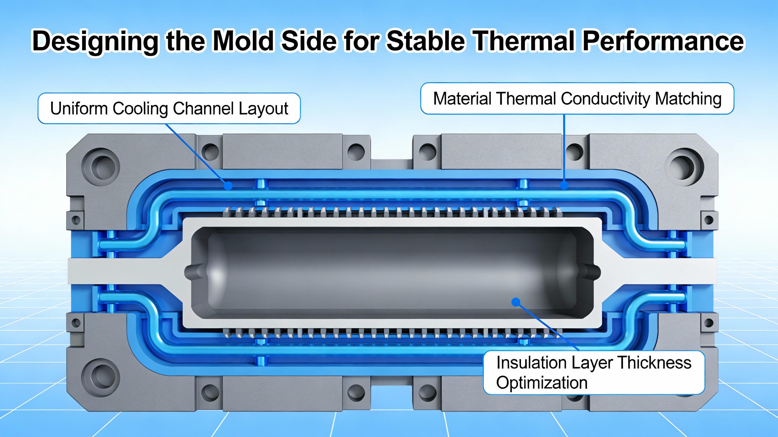
Designing the Mold Side for Stable Thermal Performance
Even the best TCU cannot overcome poor mold thermal design. Several industrial sources emphasize that uneven heat distribution is a leading cause of warpage, cycle inconsistency, and cosmetic defects.
Cooling Channels, Flow, and Temperature Difference
REGLOPLAS stresses that molds need adequate temperatureŌĆæcontrol channel surface area and sufficient crossŌĆæsection. Channels that are too small create high pressure drop, forcing you to buy larger pumps just to push coolant through the tool. There is often real costŌĆæsaving potential simply in specifying channel diameters that keep pressure reasonable while maintaining high flow.
Both REGLOPLAS and Conair highlight the importance of a small temperature rise between coolant inlet and outlet. REGLOPLAS recommends a maximum temperature difference of about 3┬░C, which is roughly 5┬░F. Plastics Engineering and ConairŌĆÖs design notes suggest that for dimensional stability, the difference between coolant entering and leaving the mold should generally not exceed about 3┬░F to 5┬░F. Larger differences indicate either insufficient flow, excessive heat load in that circuit, or blocked channels.
Conair further points out that turbulent flow in channels is essential. Turbulent flow continually moves fresh fluid against the channel wall, maximizing heat transfer. They suggest aiming for Reynolds numbers above about 4,000 and often in the 4,000 to 8,000 range; increasing flow much beyond that range does little for cooling but wastes pump horsepower.
North Slope Chillers and Retlaw Industries both echo this emphasis on turbulent flow. Laminar flow behaves like stacked layers, which insulates the core fluid and leads to temperature nonŌĆæuniformity. In practice, this means choosing channel diameters and pump sizes that deliver the needed gallons per minute at the right pressure, not simply accepting whatever the plant water system can provide.
As a simple example, imagine a mold circuit where you initially see a 10┬░F rise between inlet and outlet at a given flow. If you double the flow rate while keeping other conditions similar, the temperature rise across that circuit will drop, often approaching the recommended 3┬░F to 5┬░F band. That reduction directly tightens the spread of steel temperature along the flow path and reduces dimensional variation across the part.
Circuit Layout, Balancing, and Complex Geometry
ConairŌĆÖs discussion of manifold balancing explains how unbalanced flow can create hot spots even when total pump capacity is adequate. If shorter channels or circuits with fewer restrictions steal flow from longer ones, those starved regions will run hotter and cool more slowly. Using balanced manifolds and adjusting valves so each parallel circuit sees similar flow is critical, particularly for multiŌĆæcavity molds.
North Slope Chillers detail how traditional drilled channels in straight lines often struggle with complex geometries like deep cores, ribs, or bosses. Designers use baffles to force flow across a channel, bubblers to carry coolant into narrow cores and let it spill back, and thermal pins that use internal phase change to move heat quickly to the main cooling line. For advanced tooling, conformal cooling ŌĆō channels that follow the threeŌĆædimensional shape of the part ŌĆō dramatically improves coverage and can cut cycle times while reducing defects.
RealŌĆæworld defect patterns back this up. Delta T Systems notes that uneven heat distribution causes warpage, color shading, and premature freezeŌĆæoff in injection molding. Plastics Engineering adds that the fixed half of a mold often has better cooling than the moving half, creating asymmetric contraction and distortion unless separate circuits and temperatures are tuned. Optimized circuits, with separate paths for core and cavity and appropriately adjusted coolant temperatures, help equalize cooling and reduce distortion.
Mold Temperature vs. Cycle Time
Temperature has a direct, quantifiable impact on cycle time. REGLOPLAS provides a useful rule of thumb: for each degree Celsius increase in mold temperature, cooling time rises by about two percent. One degree Celsius corresponds to about 1.8┬░F, so raising mold temperature roughly 2┬░F increases cooling time by about two percent.
Consider a part whose cooling time is 12 seconds at a given mold temperature. If the mold temperature drifts upward by about 18┬░F (roughly 10┬░C) because of insufficient cooling capacity or fouled channels, the cooling phase could lengthen by about 20 percent, to around 14 or 15 seconds. When cooling accounts for the majority of a cycle, that increase directly cuts throughput. North Slope Chillers points out that the cooling and recovery stage can represent about 80 percent of the total manufacturing time for a part, so controlling mold temperature tightly is one of the most powerful levers for reducing overall cycle time.
The implication is clear. Temperature control is not merely about avoiding defects; it is also about locking in cycle time and capacity. From a powerŌĆæsystems view, slower cycles mean machines run longer for the same output, increasing total energy consumption on both the processing and temperature control sides.
Choosing and Specifying Temperature Control Equipment
Once the mold is designed for good thermal behavior, the next decision is which equipment will heat and cool it. Several sources from the plastics and medical manufacturing sectors outline the capabilities of modern TCUs and chillers and the gains from more advanced control strategies.
Accuracy, Stability, and Control Strategy
Polyshot describes mold temperature controllers as devices that continuously regulate mold temperature by circulating water or oil through channels. Advanced controllers use precise sensors, integrated heaters, and sophisticated cooling units to automate the temperature profile during the molding cycle. The key performance indicators are temperature accuracy, stability, and uniformity across the mold surface.
Delta T Systems reports that their packaged chillers can hold process temperatures within about ┬▒0.5┬░F. That level of control is important for tightŌĆætolerance parts and for materials whose properties are very sensitive to cooling rate and crystallinity, such as certain engineering and medicalŌĆægrade resins.
Medical manufacturing guidance from MedŌĆæTech Insights explains how newer TCUs use variableŌĆæspeed pumps and ╬öTŌĆæbased control. Instead of simply running a pump at full speed, the controller targets a specific temperature difference between the coolant entering and leaving the mold. Once the setpoint is reached, the pump adjusts speed to maintain that small ╬öT. The article describes this as a game changer, noting that it can cut pumpŌĆælevel power consumption by roughly 50 to 90 percent, depending on the application, while shortening cycle times by enabling more targeted cooling.
They provide a comparison in which a centrifugalŌĆæpump TCU with ╬öT control may use about 1,160 kilowattŌĆæhours per year in a specific threeŌĆæshift application, while an older peripheral impeller system uses around 14,495 kilowattŌĆæhours for the same job. Even without assigning a specific electricity price, the orderŌĆæofŌĆæmagnitude difference illustrates how much room there is to reduce pumping energy with better control.
System Size, Range, and Integration with Chillers
PlantŌĆæwide refrigeration and temperature control can represent a large share of operating cost. MedŌĆæTech Insights notes that around sixty percent of a plantŌĆÖs total lifecycle cost can be tied to process cooling and refrigeration. That is why Delta T Systems, Thermal Care, and others emphasize energyŌĆæefficient designs such as variableŌĆæspeed compressors and condenser fans. Delta T Systems reports that their packaged chillers can deliver up to about fifty percent energy savings relative to conventional cooling, with simple payback times as short as three years.
Thermal Care customer case studies support this kind of improvement. One plastics processor reported that a new chiller unit consumed less than half the energy of the unit it replaced while providing more stable cooling, leading to expected energy cost savings of about forty thousand dollars and enabling capacity expansion. Another reported energy savings better than thirty percent after installing a new chiller, along with eligibility for tax and utility incentives due to the efficiency gains.
From a powerŌĆæsystem reliability angle, these savings matter twice. First, lower annual energy use cuts operating cost. Second, more efficient equipment typically draws less peak power and responds more gracefully during transients, making it easier to support with backup power systems and reducing stress on power distribution equipment.
Sizing TCUs and chillers involves matching their heating and cooling capacity to the resin, mold size, and required cycle time. Conair advises that when hot runners are present, it is reasonable to add approximately 0.15 ton of cooling capacity per kilowatt of hotŌĆærunner heating load when sizing central cooling. They also recommend selecting pumps so that the required flow and pressure fall near the middle of their performance curves rather than at the extremes. This avoids overloading motors and seals and extends equipment life.
Power and Reliability Considerations for Temperature Control Loads
From the standpoint of a power system specialist, TCUs and chillers behave as a cluster of large, often continuous loads with significant starting currents. Plants sometimes overlook them when planning UPS capacity or generator sizing, focusing instead on machine drives and control systems. Yet if cooling fails during an outage, parts may stick in molds or degrade, and restart may require clearing or requalifying tools.
A reliabilityŌĆæoriented approach includes several measures. Large chillers and highŌĆætemperature TCUs should be connected so that they can be restarted in a staggered fashion after a loss of power, preventing simultaneous inrush currents from overwhelming backup supplies. VariableŌĆæspeed compressors and pumps, which are already attractive for energy efficiency as described by Delta T Systems and MedŌĆæTech Insights, also tend to start more softly than acrossŌĆætheŌĆæline motors. Finally, critical molds or lines that cannot tolerate prolonged stops may justify selective backup for their temperature control equipment, rather than trying to support every auxiliary in the plant.
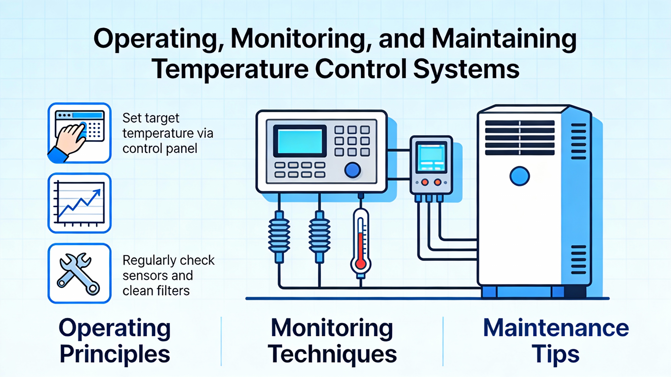
Operating, Monitoring, and Maintaining Temperature Control Systems
Even wellŌĆædesigned systems drift out of spec without maintenance. A variety of industry sources emphasize the same core themes: water quality, sensor accuracy, flow monitoring, and data logging.
Water Quality, Scaling, and Leaks
Conair details how ordinary cooling water contains minerals such as iron, sulfur, and calcium. On warm surfaces like mold channels, bubblers, and heater elements in TCUs, these minerals deposit as scale that acts as insulation. Open cooling towers accelerate this effect because water evaporates and leaves minerals behind, concentrating them over time. ClosedŌĆæloop systems scale more slowly but are not immune.
Best practice includes regular chemical descaling of circuits, auxiliaries, and molds, along with periodic testing of water clarity, color, odor, and biological load. Some processors choose demineralized water to slow scaling, accepting the higher cost and complexity as a tradeŌĆæoff for more stable heat transfer.
Leaks present a different risk. Conair explains that internal water leaks in molds not only reduce cooling efficiency but can cause cosmetic defects known as water marks, sometimes with rust or mineral discoloration. These occur when leaks allow water to reach the plastic surface, flash to steam, and displace melt. The recommended remedies are either to repair and refinish the crack or, if that is not immediately possible, to isolate the leaking circuit and operate it under slight negative pressure using a specialized TCU that pulls rather than pushes water.
Flow, Temperature Logging, and Early Fault Detection
Both Delta T Systems and Retlaw emphasize proactive monitoring. Logging mold inlet and outlet temperatures and coolant flow for each mold at each run allows trend analysis. A gradual increase in temperature difference across a tool, or a slow decline in flow at a given pump setting, often signals developing problems such as scaling, partial blockages, or pump wear long before they cause scrap or downtime.
Delta T Systems recommends cleaning filters, inspecting seals, and checking for small leaks regularly. They highlight that minor problems like sensor drift or tiny leaks accumulate over time into major stability issues if unnoticed. In rubber molding and blow molding, they note that cavity temperature sensors combined with PID control can equalize cure times and improve heat balance across cavities, respectively.
From an electrical reliability perspective, such monitoring reduces nuisance trips and unexpected load changes. A chiller compensating for fouled heat exchangers by running at higher load without operators realizing it can push a power system close to its limits during hot weather or coincident peaks. Trend data on coolant temperatures and system load can inform both maintenance and energy management.
Drying, Preheating, and Material Handling
Thermal management in plastics starts before pellets ever hit the hopper. Solex ThermalŌĆÖs discussion of heating and cooling plastic polymers highlights that many polymers, such as polycarbonate, nylon, and PET, are hygroscopic and absorb moisture from the air. If not properly dried, moisture leads to visual defects like streaking and to hydrolysis that breaks polymer chains, reducing molecular weight and mechanical performance.
Traditional dehumidifying dryers circulate heated air through a desiccant bed and around pellets, while rotary drum dryers use a rotating desiccant wheel and can be about forty percent more energy efficient. Vacuum dryers lower the boiling point of water, allowing rapid drying in about one sixth the time of conventional desiccant dryers, reducing the risk of thermal degradation from prolonged heating.
Indirect plate heat exchangers can preheat or cool pellets by conduction, with pellets flowing between hollow plates carrying hot or cold water. This approach can precisely control pellet outlet temperature with minimal emissions and no need for highŌĆævolume hot air streams.
While these systems are not part of mold temperature control per se, they are integral to a plantŌĆÖs overall thermal and power balance. Drying systems, like chillers, are large electrical loads. Coordinating their operation with production schedules and with other major loads can prevent unnecessary peaks, and their energy efficiency directly affects the total cooling load that TCUs and chillers must remove downstream.
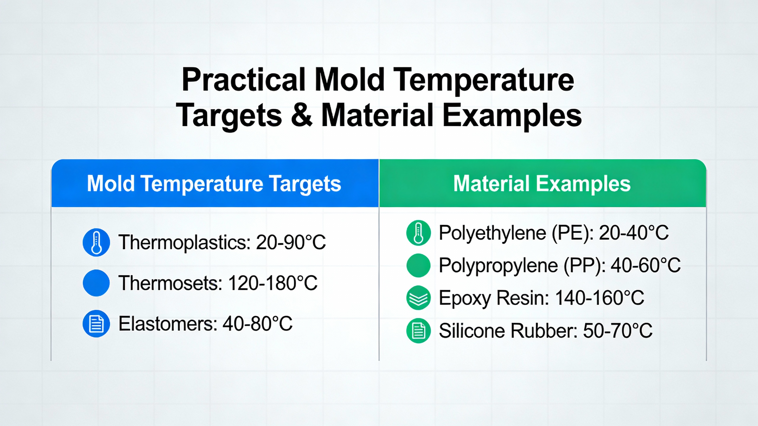
Practical Mold Temperature Targets and Material Examples
Multiple sources provide guidance on typical mold temperatures for common plastics. One materials overview notes that in injection molding, polypropylene molds often run with coolant temperatures from about 68┬░F to 140┬░F, polyethylene from about 68┬░F to 120┬░F, ABS from around 150┬░F to 185┬░F, polycarbonate from roughly 175┬░F to 250┬░F, nylon from about 150┬░F to 220┬░F, and PET from about 175┬░F to 275┬░F. A plastics engineering article focusing on mold temperature control gives similar ranges and observes that higherŌĆæmolecularŌĆæweight grades usually require higher mold temperatures because they flow less readily.
These ranges are not arbitrary. If mold temperature is set too low, the melt may freeze prematurely in thin sections, yielding short shots, weld lines, and high internal stress. If it is set too high, cooling times stretch and shrinkage increases, and surface quality can suffer. The consensus across articles from Danke Mold, MedŌĆæTech Insights, and others is that processors should start within the resin supplierŌĆÖs recommended moldŌĆætemperature range and, for demanding environments, favor the upper end of that range to allow internal stresses to relax.
As a concrete scenario, consider a medical device housing molded in ABS with a recommended mold temperature around 150┬░F to 185┬░F. If a plant runs molds near the bottom of that range to shave a second off cycle time, parts may leave the mold with higher frozenŌĆæin stress. When those devices later see elevated ambient temperatures in sterilization or field use, cracking or warpage may appear. Running closer to 180┬░F, while slightly lengthening cooling, can produce parts with better longŌĆæterm dimensional stability and mechanical performance.
For very highŌĆætemperature applications that replace metal with plastic, such as PEEK or Torlon parts operating near 400┬░F or higher, Vital Plastics underscores that molds must be heated to roughly 350┬░F to 400┬░F and cooled uniformly. Tool steels like H13 or stainless grades are chosen for strength and corrosion resistance, and berylliumŌĆæcopper inserts are used strategically where extra thermal conductivity is needed. All of this pushes TCUs, heaters, and cooling circuits toward their limits, making both thermal and powerŌĆæsystem design more demanding.
FAQ: Focused Questions on Thermal Management for Plastic Processing
How tight should mold temperature control really be?
For many commodity applications, maintaining mold temperature within a few degrees Fahrenheit is adequate, provided the temperature is uniform across the mold. However, equipment vendors such as Delta T Systems cite practical control bands as narrow as ┬▒0.5┬░F on their packaged chillers. PlasticsŌĆæsector technical articles explain that the more critical the part, the more that steel temperature in the cavity ŌĆō not just coolant temperature ŌĆō should be explicitly measured and controlled, often using multiple tempering circuits and continuous monitoring of flow, inlet, and outlet temperatures.
When is water no longer sufficient as a heatŌĆætransfer medium?
REGLOPLAS and Conair both emphasize that standard waterŌĆæbased systems are preferred up to around 190┬░F because of waterŌĆÖs superior heatŌĆætransfer properties and cost. Pressurized water systems can extend that range to about 480┬░F, which covers many highŌĆætemperature engineering resins. Above that, or in cases where water is not acceptable for material or process reasons, oilŌĆæbased TCUs are used. HighŌĆæperformance resins like PEEK, which may need mold temperatures near 350┬░F to 400┬░F and very high barrel temperatures, often sit in the transition zone where pressurized water may be possible but oil is common, depending on tool and machine design.
How does better temperature control reduce overall plant energy and power stress?
Several industry sources converge on the same picture. MedŌĆæTech Insights notes that process cooling and refrigeration account for roughly sixty percent of plant lifecycle costs, so energyŌĆæefficient TCUs and chillers have outsized impact on operating expenses. Delta T Systems reports that variableŌĆæspeed compressors and advanced controls can cut cooling energy use by around half, with payback periods as short as three years. Thermal CareŌĆÖs customer examples show energy reductions of thirty to fifty percent when older equipment is replaced. On top of this, strategies like ╬öTŌĆæbased pump control can reduce pump energy by 50 to 90 percent. From a powerŌĆæsystem perspective, these improvements reduce both annual energy use and peak electrical demand, making it easier to size and operate UPS systems, inverters, and backup generators that support critical lines.
Ultimately, temperature control in plastics processing is both a thermal and an electrical reliability problem. If you treat TCUs, mold circuits, chillers, and dryers as an integrated, powerŌĆæaware system ŌĆō designed around the real thermal behavior of your polymers ŌĆō you can simultaneously raise product quality, increase throughput, and reduce stress on your power infrastructure.
References
- https://www.academia.edu/30469169/How_Time_and_Heat_Affect_the_Properties_of_Plastics
- https://books.byui.edu/plastics_materials_a/thermal_changes_in_p
- https://scholarsmine.mst.edu/cgi/viewcontent.cgi?article=7598&context=mec_aereng_facwork
- https://www.appstate.edu/~clementsjs/polymerproperties/plastics_high_temp
- https://production.cbts.edu/Textbook/63uWfK/897780/PlasticMaterialMeltingTemperature.pdf
- https://ojs.cnr.ncsu.edu/index.php/BRJ/article/view/22977
- https://www.plasticsengineering.org/2024/11/the-importance-of-mold-temperature-control-in-injection-molding-007341/
- https://www.hiwattinc.com/how-to-control-the-temperature-in-industrial-plastics-manufacturing?srsltid=AfmBOoo7iq31eK3Wl--9sQMLUzQT3nb4DxM5zehXGdHoFY1UE4lZZfx7
- https://www.atlasfibre.com/selecting-the-right-material-for-operating-temperature/
- https://www.plasticstoday.com/plastics-processing/5-tips-for-choosing-the-best-temperature-control-system


 Videos
 News
News Applications


Leave Your Comment