Why VFD Sizing Matters To Reliability and Power Quality
In commercial and industrial plants today, variable frequency drives sit right alongside UPS systems, inverters, and sensitive electronic loads. One selection guide notes that roughly 40% of newly installed motors now arrive with a VFD somewhere in the system, which means your drive sizing decisions directly affect not just the motor, but also upstream switchgear, power conditioning, and protection.
From a reliability perspective, I see the same pattern over and over: a drive that looked ŌĆ£rightŌĆØ on paper nuisance-trips in a hot panel, refuses to start a conveyor under heavy product, or pushes enough harmonic distortion back into the supply that the UPS or building transformers start to complain. The root cause is almost always the same. Someone chose the VFD by horsepower and price instead of current, duty class, environment, and stopping behavior.
Engineering sources such as Electricity Forum, Industrial Automation Co, Danfoss, AutomationDirect, and Control Engineering all converge on a simple principle. A VFD does not create horsepower; it supplies controlled current, voltage, and frequency so the motor can produce the torque the process needs. You size the drive to the motor and application, not the other way around.
This guide walks through a practical, current-based method for sizing VFDs that I use when I review plants and critical facilities. The goal is not just to ŌĆ£make it run,ŌĆØ but to protect the motor, keep the VFD inside its thermal limits, and avoid surprises for your UPS and upstream protection.
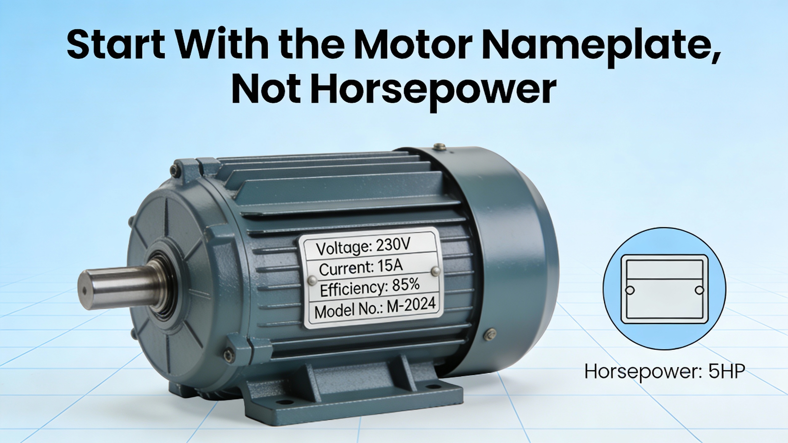
Start With the Motor Nameplate, Not Horsepower
What the Nameplate Really Tells You
Every credible VFD sizing reference starts in the same place: the motor nameplate. Dalroad, Electricity Forum, AutomationDirect, Danfoss, and VFDS.com all stress that full-load amps, not horsepower, is the primary sizing metric.
A typical threeŌĆæphase induction motor nameplate will list at least voltage, frequency, horsepower, fullŌĆæload amps, speed, service factor, insulation class, and enclosure rating. Some will also note whether the motor is inverter duty and include multiple voltages, for example 230/460 V with fullŌĆæload amps like 13.4/6.7 A. Danfoss reminds us that VFDs themselves are not multiŌĆævoltage devices; they are built for specific voltage classes, so you must know which voltage the motor will actually run on.
FullŌĆæload amps is the current drawn at rated horsepower and speed. Electricity Forum and Industrial Automation Co both define proper sizing as choosing a drive whose continuous output current is greater than or equal to the motor fullŌĆæload amps at that operating voltage. VFDS.com frames horsepower as a label that helps narrow the catalog, but not as a safe sizing criterion on its own. Two motors marked 20 hp can differ significantly in current depending on efficiency and speed.
In practice, I always start by photographing the nameplate during a walkdown, as EECO recommends, then transcribing:
- Voltage and frequency
- FullŌĆæload amps at that voltage
- Service factor
- Insulation class
- Enclosure and ambient rating
Once you have that, horsepower becomes a sanity check.
Example: Two 20 hp Motors, Two Different Drives
Consider two 20 hp, 460 V motors driving similar fans. One has a nameplate fullŌĆæload current of 27 A, the other 32 A because of different design and efficiency. If you pick a ŌĆ£20 hpŌĆØ VFD that is rated for 28 A continuous output based on a quick catalog scan, you may be fine on the first motor and underŌĆæsized on the second.
Following the guidance from Electricity Forum and Danfoss, the correct process is to ignore horsepower at this stage and size to fullŌĆæload amps. The 27 A motor can use a VFD whose continuous output rating is at least 27 A with suitable overload for its duty class. The 32 A motor needs a larger frame with continuous current above 32 A, even though both motors share the same horsepower marking.
That is why so many ŌĆ£mystery tripsŌĆØ disappear the moment a drive is upsized one frame to match actual current, not the sticker on the motor.
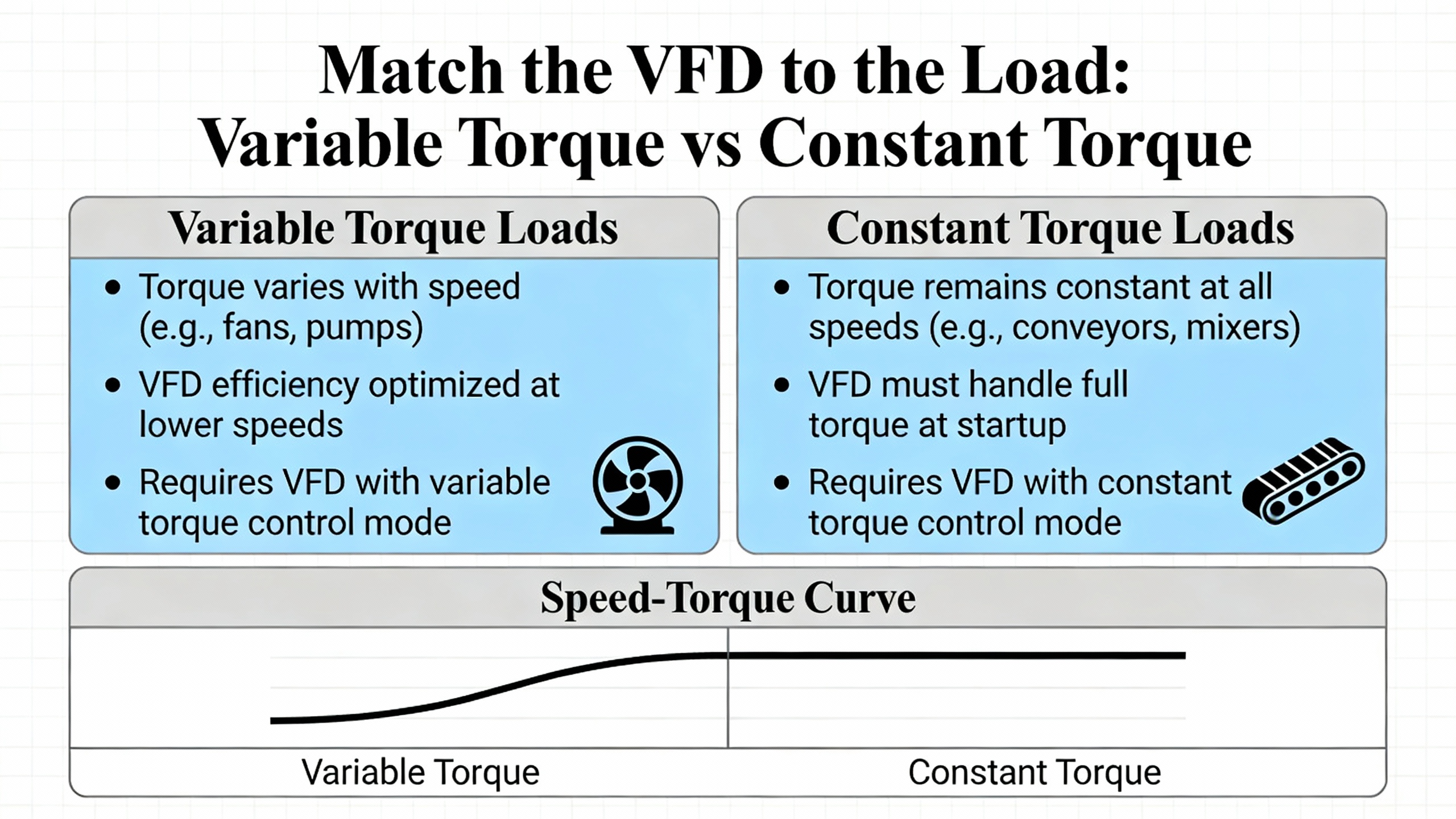
Match the VFD to the Load: Variable Torque vs Constant Torque
Understanding Load Type
Electricity Forum, Industrial Automation Co, AutomationDirect, EECO, and EmotorsDirect all converge on the need to classify the driven load before you settle on a duty class.
VariableŌĆætorque loads are dominated by centrifugal effects. Fans, coolingŌĆætower fans, many HVAC pumps, and some screw compressors fall into this category. Torque requirement falls roughly with the square of speed, and power falls with the cube of speed. Control Engineering and ConsultingŌĆæSpecifying Engineer note that this is why variableŌĆæspeed operation on fans and pumps can yield very large energy savings compared with constantŌĆæspeed throttling.
ConstantŌĆætorque loads require essentially the same torque from low speed to base speed. Conveyors, escalators, bucket elevators, cranes, mixers, extruders, punch presses, positiveŌĆædisplacement pumps, and many crushers are typical examples cited by EECO, Industrial Automation Co, and EmotorsDirect. These applications often start under load, sometimes with sticky or impactŌĆætype product, and they punish any margin you failed to include in VFD selection.
VT vs CT Duty Ratings and Overload
Most manufacturers publish two ratings on the same frame: a variableŌĆætorque or ŌĆ£normal dutyŌĆØ rating and a constantŌĆætorque or ŌĆ£heavy dutyŌĆØ rating. Industrial Automation Co describes VT drives as providing roughly 110ŌĆō120% overload for 60 seconds, while CT drives are designed for about 150% overload for 60 seconds. Electricity Forum notes that some constantŌĆætorque applications can even demand 150ŌĆō200% of rated current during starting or worstŌĆæcase operation.
EmotorsDirect and VFDS.com both caution that using a constantŌĆætorque rating on a simple fan or pump does not improve performance; it just costs more and wastes thermal headroom. Conversely, putting a lowŌĆæoverload VT drive on a heavily loaded conveyor is an invitation to nuisance trips, hot electronics, or a motor that never quite reaches speed.
Simple Overload Calculation Example
Electricity Forum gives a clear numeric example that is easy to apply. Suppose you have a 65 A motor on a variableŌĆætorque pump. You should choose a drive whose intermittent or overload rating is at least 115% of that current, about 74.8 A. For a constantŌĆætorque conveyor with the same 65 A motor, you look for a drive that can supply 150% of 65 A, or 97.5 A, for the specified overload period.
That calculation is not optional; it is your assurance that the VFD will actually start the load and ride through shortŌĆæterm disturbances without tripping into overcurrent or overvoltage faults.
Special Case: Regenerative Loads
Some constantŌĆætorque applications not only demand high starting torque, they also push energy back into the DC bus during operation. EECO and Industrial Automation Co highlight elevators, cranes, hoists, and downhill conveyors as classic examples. When these loads overŌĆæhaul the motor during lowering or deceleration, they regenerate power into the drive.
If that energy has nowhere to go, DCŌĆæbus voltage climbs until the VFD trips on overvoltage or, in the worst case, damages its electronics. You address this either by adding a properly sized dynamic braking resistor or by specifying a drive with an active front end that can return energy to the line. Industrial Automation Co frames the choice by stop frequency and severity: occasional moderate decelerations might get by with controlled ramps, but frequent fast stops on vertical loads almost always justify a braking resistor or regenerative unit.
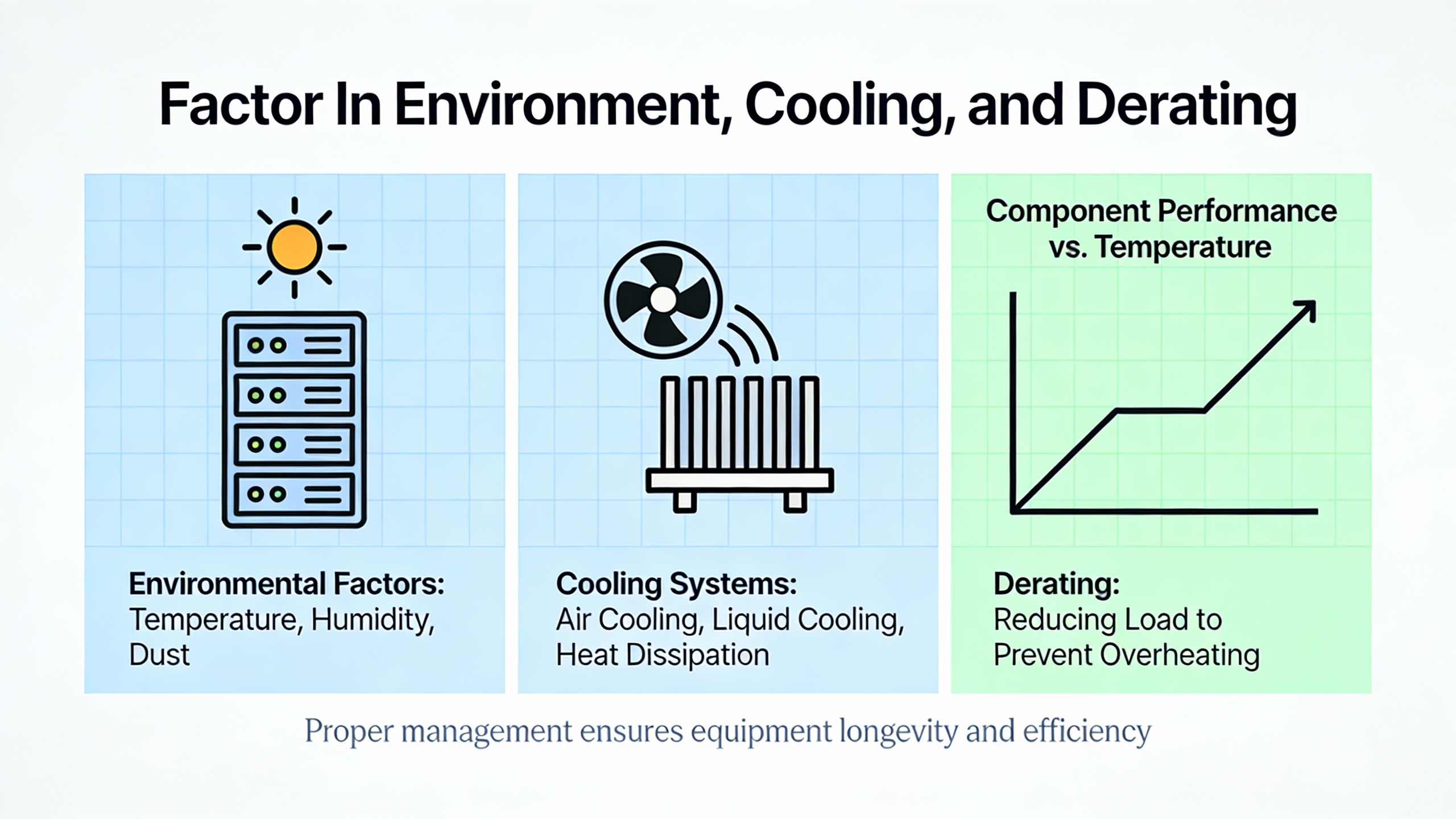
Factor In Environment, Cooling, and Derating
Why Drives Trip in Real Panels
On paper, many drive selections look perfect. In the field, I often find those same drives mounted in cramped, warm panels with marginal ventilation, running near full current on hot summer days. Industrial Automation Co and AutomationDirect both warn that ambient temperature, altitude, enclosure airflow, and carrier frequency all reduce the usable current of a VFD.
AutomationDirect notes that most drives operate at full rating up to a moderate altitude, but above that threshold the thinner air cannot carry away heat as effectively, which forces derating or oversizing. EmotorsDirect and VFDS.com report similar guidance and add that in hot locations you may need extra cooling or a drive with flangeŌĆæmount heat sinks that stick outside the enclosure to keep electronics cooler.
Industrial Automation Co quantifies this with a typical rule of thumb: at around 113┬░F panel temperature and higher carrier frequency, many drives lose roughly 5ŌĆō10% of their current capacity. If you ignore that and size the drive to motor amps with no margin, the VFD will run at or beyond its thermal limit whenever the panel heats up or filters clog.
NEMA Enclosures and Environmental Ratings
EECO provides a practical breakdown of NEMA ratings that ties directly into reliability. A VFD in a clean electrical room at a controlled temperature fits a NEMA 1, IP20 environment. Dusty areas or locations with dripping liquids call for NEMA 12, roughly IP52, to keep out contaminants. Rooftop or outdoor drives on airŌĆæhandling units or pumps typically use NEMA 3R, again around IP52, to deal with dust and rain. Food processing environments with washdown and caustic cleaners require NEMA 4 or 4X, about IP56, for enhanced sealing and corrosion resistance.
In plants where harsh environments are unavoidable, I often recommend mounting the VFD in a betterŌĆæprotected room and running VFDŌĆærated cable to the motor rather than trying to make the drive itself survive on the roof or over a process line. That approach is supported by examples from VFDS.com, where VFDs in wellŌĆæmaintained enclosures have run reliably for decades even in tough conditions.
Example: CoolingŌĆæTower Fan Drive
Industrial Automation Co describes a 30 hp, 460 V coolingŌĆætower fan with 40 A fullŌĆæload current in a hot panel at sea level, operating with an 8 kHz carrier frequency. With expected derating of about 5ŌĆō10%, a drive that is only rated for 40 A continuous output would be operating beyond its real capacity once the panel heats up.
The recommended solution is to choose a variableŌĆætorque drive with a nominal current rating of roughly 44ŌĆō46 A, so that after accounting for thermal and switchingŌĆæfrequency derating it still delivers at least 40 A. That oneŌĆæframe upsizing is usually inexpensive compared with the downtime and troubleshooting caused by chronic thermal trips.
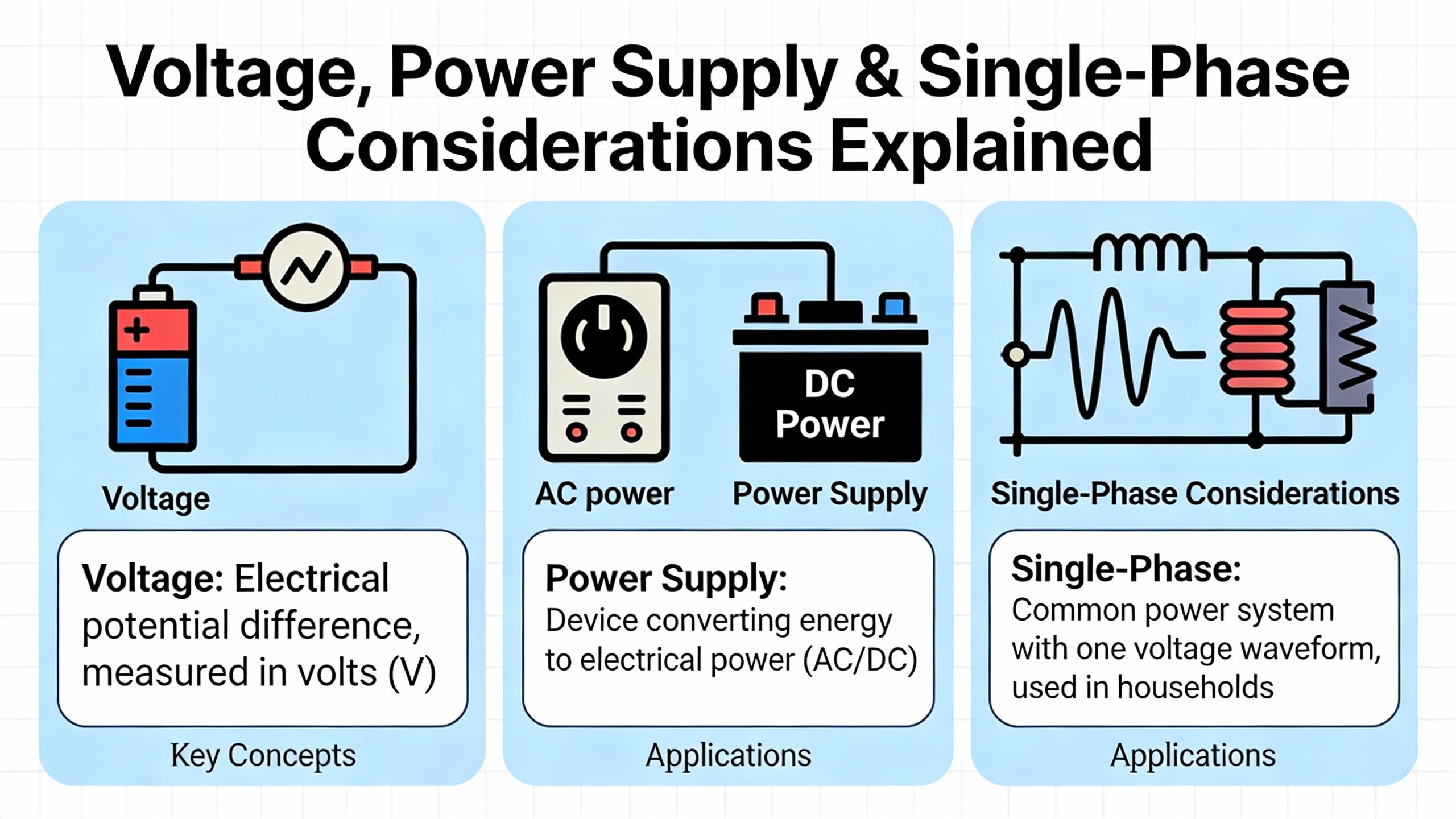
Voltage, Power Supply, and SingleŌĆæPhase Considerations
Matching Voltage and Tolerance
Danfoss emphasizes that drives are built for defined voltage classes such as 200ŌĆō240 V, 380ŌĆō480 V, or 525ŌĆō600/690 V. They are not multiŌĆævoltage devices in the way many motors are. Electricity Forum adds another layer: the driveŌĆÖs inputŌĆævoltage tolerance must cover the real high and low line at the site.
In one example, Electricity Forum considers a 575 V system whose voltage varies between about 550 and 625 V. A commercial VFD rated 575 V with +5%/ŌłÆ10% tolerance has an acceptable range of roughly 518ŌĆō603 V. This does not fully cover the 625 V highŌĆæline, so the drive would be at risk of overvoltage trips or even catastrophic failure during sustained highŌĆæline conditions. Some industrial drives with ┬▒15% tolerance span a wider range, approximately 489ŌĆō660 V in this case, better matching the actual system.
From a powerŌĆæsystem standpoint, this is the same kind of coordination you do when you specify UPS equipment. Control Engineering and ConsultingŌĆæSpecifying Engineer note that the basic rectifierŌĆōDC busŌĆōinverter architecture of a VFD is similar to that of a doubleŌĆæconversion UPS; the main difference is the control target. UPS inverters hold voltage and frequency constant, while VFD inverters vary both to control motor speed. The common architecture means that if you push a VFD outside its voltage rating, you stress semiconductors and capacitors in much the same way you would in a UPS.
SingleŌĆæPhase Supply and DeŌĆæRating
When only singleŌĆæphase power is available but you need to run a threeŌĆæphase motor, VFDS.com and DoSupply outline a practical approach. For motors up to about 3 hp with fullŌĆæload amps under roughly 10 A at 230 V, you can often use a dedicated singleŌĆæphaseŌĆæinput drive. Above that point, the input rectifier of a threeŌĆæphase drive will be significantly stressed by singleŌĆæphase operation.
The solution is to deŌĆærate by current. VFDS.com gives an example where a 10 hp motor with 28 A fullŌĆæload current requires a drive with at least twice that current rating when fed from singleŌĆæphase, so a VFD with more than 56 A output, roughly a 20 hp frame, is appropriate. DoSupply reaches the same conclusion: with singleŌĆæphase input, size the drive to about two times motor fullŌĆæload amps. Line reactors are often added in these phaseŌĆæconversion scenarios because, as VFDS.com puts it, VFDs are significant electrical ŌĆ£polluters,ŌĆØ introducing harmonics into the power system.
For facilities with UPS systems and other sensitive loads on the same bus, Control Engineering recommends considering lowŌĆæharmonic drives, active front ends, or harmonic filters to keep distortion within IEEE 519 guidance and avoid interactions between VFDs and powerŌĆæquality equipment.
StepŌĆæByŌĆæStep Sizing Method With Examples
Bringing the guidance from Danfoss, Electricity Forum, Industrial Automation Co, AutomationDirect, and others together, a robust VFD sizing method follows a logical sequence. I will illustrate it with two realŌĆæworld style examples.
Example 1: CoolingŌĆæTower Fan (Variable Torque)
You are asked to select a drive for a 30 hp coolingŌĆætower fan motor. The nameplate shows 460 V, 60 Hz, 40 A fullŌĆæload current, with a standard service factor and operation in a rooftop panel expected to reach about 113┬░F. The fan is centrifugal, so this is a variableŌĆætorque load, and starts are fairly gentle.
First, size to fullŌĆæload amps rather than horsepower. You need a VFD whose continuous VTŌĆæduty current rating meets or exceeds 40 A.
Next, apply overload requirements. Electricity Forum and Industrial Automation Co recommend about 110ŌĆō120% overload for variableŌĆætorque loads. That means the driveŌĆÖs shortŌĆæterm rating should be at least around 44ŌĆō48 A for the specified overload duration.
Then consider derating. Industrial Automation Co highlights that a drive in a hot panel at 8 kHz switching might lose 5ŌĆō10% of its current capacity. If a catalog shows a VTŌĆæduty drive frame rated 40 A continuous, derating could bring the usable current down into the midŌĆæ30 A range, which is below your 40 A motor requirement.
Based on that, you select the next larger VTŌĆæduty frame, perhaps with a nominal continuous rating of 44ŌĆō46 A. After a conservative 10% derating, you still have roughly 40ŌĆō41 A available, matching the motor nameplate and meeting overload needs. In this configuration, no braking hardware is needed because the fan coasts down without regenerating significant energy into the drive.
Example 2: Sticky Product Conveyor (Constant Torque with Braking)
Now consider a 5 hp, 460 V conveyor motor in a packaging line, with 7.6 A fullŌĆæload current. The conveyor starts under load, carries sticky product, and must decelerate quickly to avoid spillage at the discharge chute. Industrial Automation Co uses a very similar example.
Again, start with current. The drive continuous CTŌĆæduty rating must be at least 7.6 A.
Because this is a constantŌĆætorque load with heavy starts, you apply the 150% overload rule for 60 seconds cited by Industrial Automation Co, Electricity Forum, and Danfoss. That yields a required overload capability of 11.4 A. You select a CTŌĆærated drive whose data sheet explicitly states 150% overload for 60 seconds and whose overload current rating meets or exceeds that 11.4 A.
The fast deceleration requirement changes the picture. When the conveyor stops hard with product on the belt, it will drive energy back into the VFD. Industrial Automation Co warns that such overhauling loads will cause DCŌĆæbus overvoltage unless you provide an energy path. For frequent, heavy decelerations, the recommended solution is to add a dynamic braking resistor sized per the drive manufacturerŌĆÖs tables for a 5 hp motor and the desired stop time.
After you choose an enclosure appropriate to the area, confirm that wiring, fusing, and branch protection follow the driveŌĆÖs installation manual, as emphasized by Electricity Forum and the Electronics Stack Exchange discussion on VFD selection and safety. Only then can you rely on the driveŌĆÖs internal protection and programming to keep the motor and connected equipment safe.
Braking, Regeneration, and Stop Methods
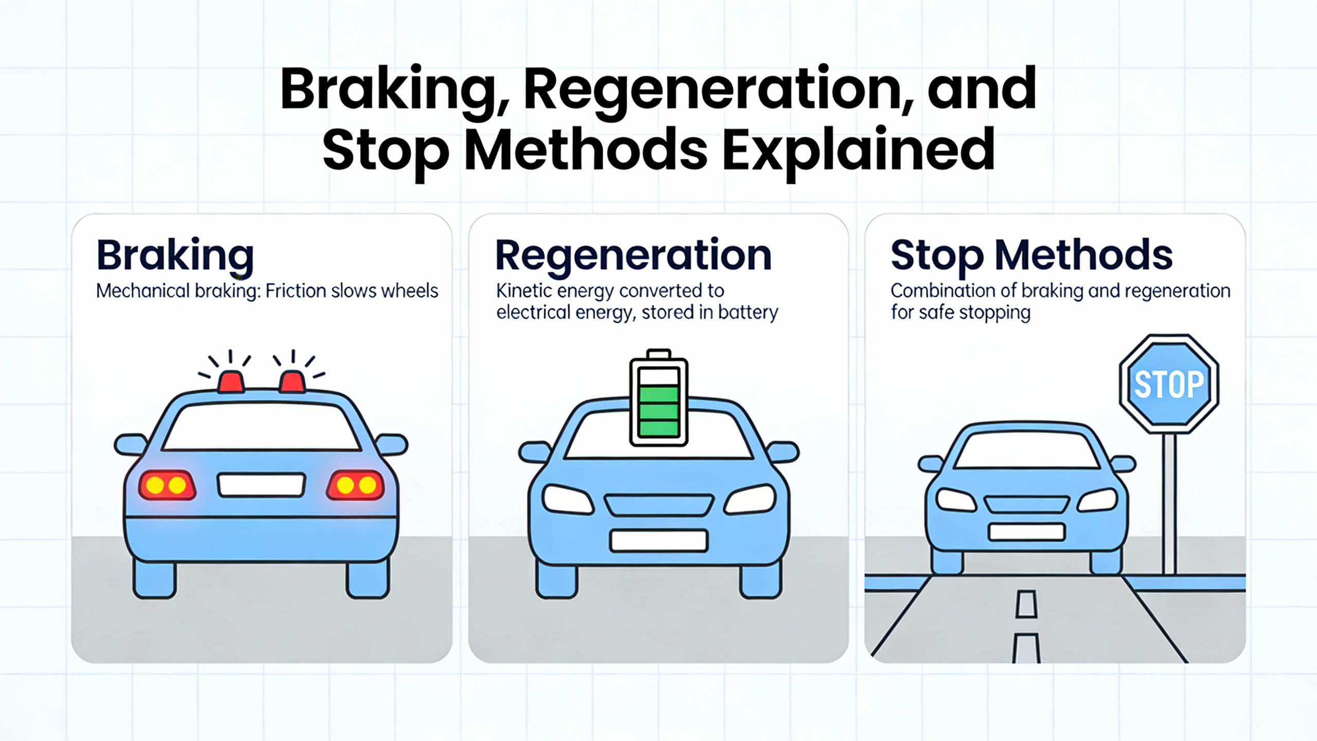
Industrial Automation Co and EECO lay out four basic strategies for handling energy during deceleration or overhauling: coasting to stop, controlled deceleration, dynamic braking, and regenerative front ends.
Coast to stop simply removes torque and lets the load wind down. It is electrically gentle but yields the longest stop time and is rarely acceptable for conveyors, hoists, or safetyŌĆæcritical equipment.
Controlled deceleration uses the driveŌĆÖs rampŌĆædown profile without dedicated braking hardware. For highŌĆæinertia fans and pumps with modest stopŌĆætime requirements, this is often enough. However, Industrial Automation Co warns that aggressive deceleration ramps on big fans or vertical loads can still push bus voltage toward the shutdown threshold.
Dynamic braking adds a resistor across the DC bus that turns regenerative energy into heat. This is the workhorse solution for conveyors, hoists, and other machinery needing faster, predictable stops. It is relatively simple and, when properly sized, very reliable.
Regenerative front ends replace the standard rectifier with actively controlled circuitry that can push energy back into the utility. This is the most capitalŌĆæintensive approach but makes sense when you have frequent, heavy decelerations or multiple overhauling axes. Control Engineering also notes that regenerative designs can improve overall power factor and reduce harmonic distortion compared with many standard drives.
From a powerŌĆæprotection standpoint, braking strategy affects upstream equipment. Dynamic resistors keep most of the transient energy in the local drive circuit, while regenerative front ends feed that energy into the bus and must be coordinated with UPS and protection settings.
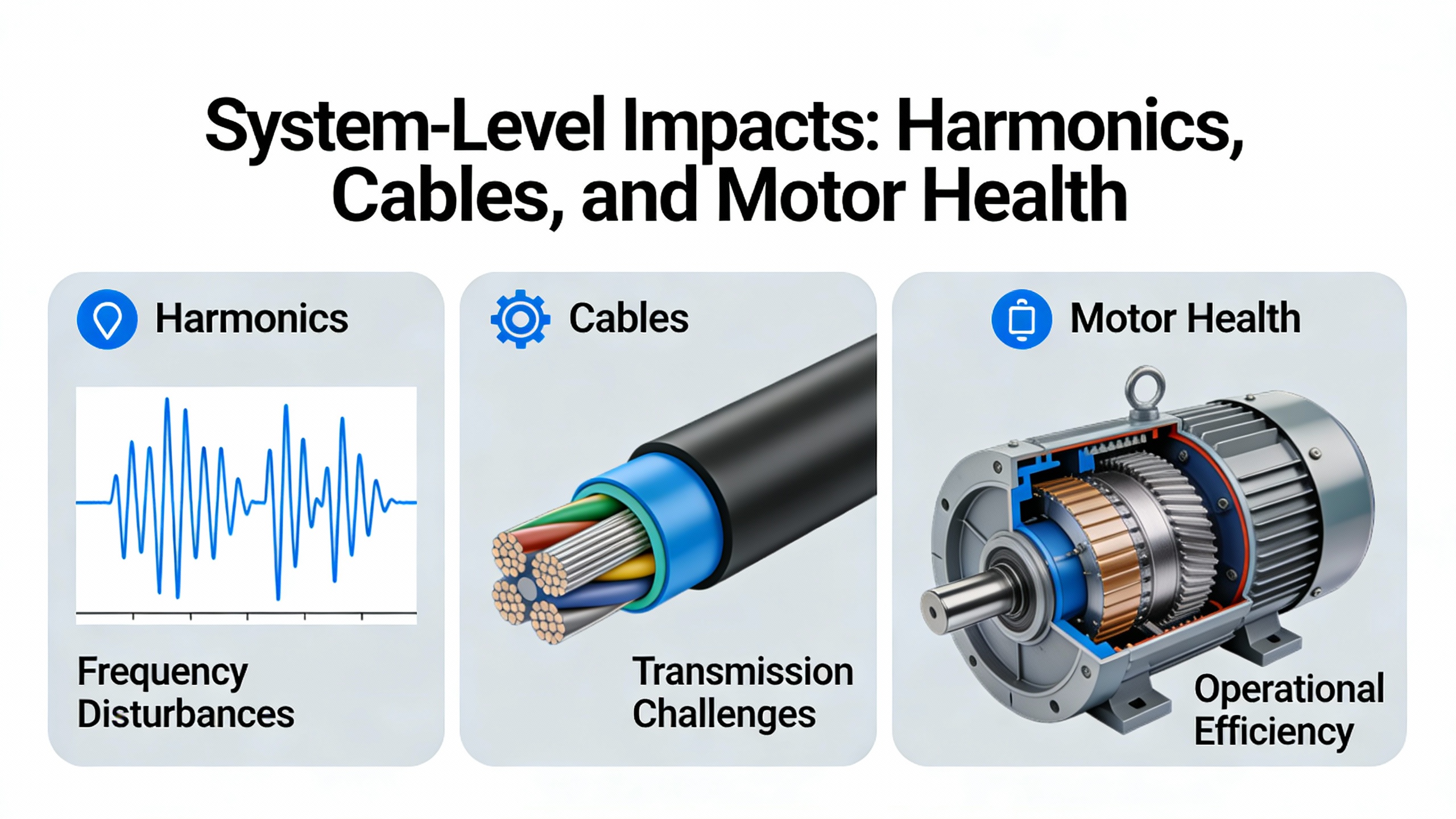
SystemŌĆæLevel Impacts: Harmonics, Cables, and Motor Health
Harmonics and Power System Interaction
Control Engineering points out that VFDs introduce harmonics into the power system because of their rectifier front ends and highŌĆæfrequency switching. CSE and EECO echo this and mention that sixŌĆæpulse rectifiers are common, with twelveŌĆæpulse or active front ends used when harmonic limits such as IEEE 519 must be met.
EECO notes that many drives above about 30 hp include a builtŌĆæin DC choke to reduce harmonics. EECO and VFDS.com also describe line reactors, often specified as 3% or 5%, as a straightforward way to reduce harmonic currents and protect both the drive and upstream equipment. In facilities with sensitive loads or limited electrical capacity, VFDS.com recommends integrating harmonic mitigation inside the same cabinet as the drive rather than relying on adŌĆæhoc external filters.
When I review electrical rooms with a mix of UPS units, VFDs, and electronic loads, I treat drives as nonŌĆælinear, sometimes ŌĆ£noisyŌĆØ neighbors. That means detailed faultŌĆæcurrent and harmonic studies are justified once the VFD population grows, particularly for large constantŌĆætorque loads or phaseŌĆæconversion applications.
Motor Cables, dv/dt, and Bearings
Control Engineering and VFDS.com warn that the pulseŌĆæwidthŌĆæmodulated output of modern IGBT drives places additional stress on motor windings and bearings. The steep voltage edges can lead to high dv/dt at the motor terminals, especially with long cable runs, and circulating currents can pit bearings over time.
Electricity Forum notes that NEMA MG1 Part 30 motors can be used with VFDs only when appropriate motor filters are applied, whereas Part 31 motors are specifically designed for inverter duty and usually eliminate the need for feeder filters across typical speed ranges. VFDS.com and EmotorsDirect add that inverterŌĆæduty motors use higherŌĆægrade insulation and often incorporate features like shaft grounding rings or insulated bearings to mitigate bearing damage.
Industrial Automation Co and VFDS.com both recommend dv/dt or sineŌĆæwave filters when running long motor leads, particularly with standard motors. These filters limit reflectedŌĆæwave overvoltages at the motor and reduce insulation stress.
Dalroad and CSE highlight the thermal side. Stator winding overheating is a leading cause of motor failure on VFD applications. CSE notes the rule of thumb that each 18┬░F rise in winding temperature roughly halves insulation life, while an 18┬░F reduction can double it. Dalroad suggests specifying at least Class F insulation and ensuring adequate cooling, especially at low speeds where shaftŌĆæmounted fans move less air.
In my own audits, many ŌĆ£VFD killed the motorŌĆØ stories trace back not to the drive itself, but to underspecified motors, long unfiltered cables, or ignoring the motor manufacturerŌĆÖs turndown limits.
Common Pitfalls and How To Avoid Them
Industrial Automation Co, AutomationDirect, VFDS.com, EmotorsDirect, DoSupply, and the Electronics Stack Exchange community all catalog the same failure modes. Drives are chosen on horsepower or cost rather than current and overload rating. Carrier frequency is cranked up to quiet the motor without checking derating tables, silently sacrificing current capacity. Aggressive decel ramps are programmed on overhauling loads with no braking path, leading to chronic DCŌĆæbus overvoltage trips. Long motor leads are run without filters, stressing windings and bearings. Hot, cramped panels and high altitudes are ignored, turning a paperŌĆæcorrect drive into a thermal problem waiting to happen.
Another subtle pitfall is documentation. The Electronics Stack Exchange discussion urges buyers to treat the quality of the VFD manual as a selection criterion. A good manual includes wiring diagrams, overload curves, derating tables, brakingŌĆæresistor sizing tables, and application notes. Without that, even an otherwise solid drive is hard to apply safely.
From a powerŌĆæsystem standpoint, the pitfall I see most often is specifying many drives into a facility without a parallel harmonic and protection review. VFDS.com calls VFDs major electrical polluters, especially when used as phase converters. Control Engineering reiterates that they are capable of disturbing power quality if not mitigated. If your plant also depends on UPS units and sensitive electronic loads, leaving harmonics to chance is not compatible with high availability.

FAQ: Quick Answers on VFD Sizing
How much larger than the motor should my VFD be? Industry guidance from Electricity Forum, Danfoss, Industrial Automation Co, and VFDS.com is clear: always start by matching or slightly exceeding the motor fullŌĆæload amps at the operating voltage. For variableŌĆætorque loads like fans and pumps, ensure the drive has about 110ŌĆō120% overload capability for roughly one minute. For constantŌĆætorque loads such as conveyors and positiveŌĆædisplacement pumps, look for about 150% overload capability for the specified duration. When derating for hot panels, altitude, or high switching frequency brings available drive current below the motor amps, step up one frame size.
Can I run multiple motors from one VFD? Industrial Automation Co notes that running multiple motors from a single VFD is acceptable if the sum of motor fullŌĆæload amps and required overload are within the driveŌĆÖs capability and each motor has its own overload protection. However, you lose the ability to individually speedŌĆæcontrol motors, and starting and stopping sequences become more complex. Careful coordination of overload settings and wiring, following the manufacturerŌĆÖs recommendations, is essential.
Do I always need an inverterŌĆæduty motor for a VFD? Electricity Forum, VFDS.com, EmotorsDirect, and AutomationDirect all agree that inverterŌĆæduty motors are strongly preferred, particularly at extended speed ranges, high switching frequencies, or with long cable runs. Standard motors can work in milder applications if cable lengths are short, carrier frequency is moderate, and dv/dt or sineŌĆæwave filters are used where appropriate. When in doubt, consult the motor manufacturerŌĆÖs guidance on allowable turndown and overspeed with VFD operation.
Closing
When you treat a VFD as just another line item on a bill of material, you end up with nuisance trips, hot motors, and unhappy powerŌĆæquality meters. When you treat it as an engineered powerŌĆæconversion device that must fit your motor, load, environment, and upstream infrastructure, you get quiet, predictable operation and longer equipment life. If you approach drive sizing by current, duty class, derating, braking, and harmonics rather than nameplate horsepower alone, you will not just make the motor run; you will protect the entire power system that feeds it.
References
- https://admisiones.unicah.edu/Resources/MkcbtA/0OK002/VariableFrequencyDrivesForDummies.pdf
- https://www.gohz.com/vfd-selection-guide?srsltid=AfmBOoodd1GyVLkltcOXloOK18cL7iQ-buuggqB_hCbcPEVTAepT06JI
- https://library.automationdirect.com/how-to-select-a-variable-frequency-drive/
- https://www.controleng.com/variable-frequency-drive-advice-best-practices-for-engineers/
- https://www.csemag.com/how-to-select-a-vfd/
- https://eecoonline.com/inspire/how-to-size-a-vfd
- https://www.precision-elec.com/variable-frequency-drives-vfds-guide/?srsltid=AfmBOoqEmN1QCSeUUNLW9cybfQrqsqyY5zsbqESswQhtOTTls2ifPaY6
- https://library.e.abb.com/public/02954f20cb09454ebf48714102f27d0b/Sizing_VFDs_for_HVAC_Applications_Based_on_the_NEC.pdf
- https://coastapp.com/blog/vfd-variable-frequency-drive/
- https://www.dalroad.com/resources/how-to-read-a-motor-nameplate-and-why-its-critical/


 Videos
 News
News Applications


Leave Your Comment