Integrating industrial robots into a production line is never just about installing an arm and teaching a few points. Behind every smooth, repeatable motion is a motion control system that acts as the real nervous system of the robot. For plant teams responsible for uptime, power quality, and protection, understanding how motion control works is the difference between a reliable robotic cell and a chronic source of faults and nuisance trips.
In this article, I will walk through how motion control systems coordinate multiŌĆæaxis industrial robots, using the component-level view described by Motion Automation Intelligence and the design guidance outlined in Medical Device & Diagnostic Industry. Along the way, I will highlight where power electronics, drives, and feedback interact with your power infrastructure, and how to make sound choices that support both motion performance and long-term reliability.
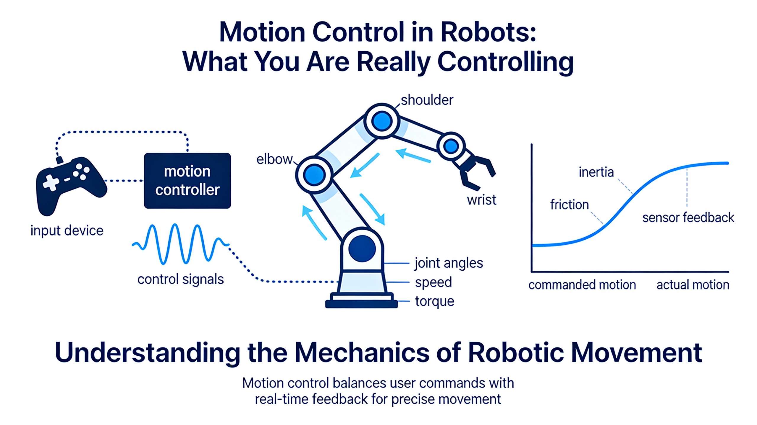
Motion Control in Robots: What You Are Really Controlling
A motion control system regulates a machineŌĆÖs position, velocity, force, and sometimes pressure. As Motion Automation Intelligence explains, it does this through four core elements working together: the motion controller, the drive, the motor, and, in closed-loop systems, the feedback device.
In a typical industrial robot, those elements are present whether you see them explicitly or not. A multiŌĆæaxis Cartesian robot moving boxes, or a small SCARA arm handling parts, will always need something that computes trajectories, something that converts lowŌĆævoltage commands into highŌĆæpower current, an electromechanical device to generate torque or thrust, and a way to measure where the mechanism actually is.
A design guide in Medical Device & Diagnostic Industry emphasizes that motion design should start with a very practical set of questions: Are you controlling position, speed, force, or some combination? Is accuracy or repeatability more important? How many axes does the robot need, and do those axes have to move in coordinated fashion (for example, XŌĆōYŌĆōZ following a smooth path) or can they move independently? Those questions shape every downstream choice.
Consider a simple twoŌĆæaxis gantry that picks cartons from a conveyor and drops them into cases. If you only need to hit the same grid positions and are tolerant of slight variation in path, you may be controlling mostly position and repeatability, with two coordinated axes. A more advanced inspection robot tracing a contour over a part may require precise velocity and continuous path control, with three or more axes interpolated together. In both cases, the four motion control elements are the same; what changes is how tightly they must be integrated and how demanding the trajectories are.
The Motion Controller: Brain of the Robotic Cell
Medical Device & Diagnostic Industry calls the motion controller the system ŌĆ£brain,ŌĆØ and notes that it is usually the hardest part to change later. That is because it embeds the hardware, firmware, communication protocols, and programming tools that define how your robot can move and how it will talk to the rest of your plant.
At its core, the motion controller runs algorithms that calculate trajectories and velocities, such as interpolators and control loops. As described in the Motion Automation Intelligence material, it outputs command signals to the drive, and, when feedback is available, refines those commands in real time. In closed-loop servo systems, the controller reads encoder or resolver feedback and updates motor current on the order of about one thousand times per second, as documented in Medical Device & Diagnostic Industry. That servo update rate of roughly one millisecond per cycle is what allows industrial robots to generate smooth velocity profiles and react quickly to disturbances such as unexpected loads or minor collisions.
From an integration standpoint, motion controllers typically come in two forms. BusŌĆæbased cards plug into a host computer backplane and rely on that computer for power and user interfaces. StandŌĆæalone units have their own power supply and a communication port, such as a serial link, and can sometimes replace a separate machine computer entirely. The industry experience reflected in Medical Device & Diagnostic Industry is that these two approaches are similar in space and cost, so the real choice is about system architecture and maintainability rather than footprint.
When you are integrating robotics into a production environment that must stay online, the selection criteria for the controller become far more than a spec sheet exercise. The same design guide highlights several capabilities that are particularly critical for industrial robots. The controller should support the mix of motors you intend to use, often both stepper and servo axes in one system. Its programming language and setup tools must be powerful yet practical for your team to maintain. It should support multitasking so that motion, safety checks, and communication can run logically in parallel. For robotics specifically, coordinated motion features such as linear and circular interpolation, electronic gearing, and camming are essential for coordinated paths. Robust error handling and synchronization features matter as much for uptime as peak speed, because they determine how gracefully your robot responds to faults or power disturbances.
Imagine a threeŌĆæaxis gantry robot that must draw a straight line across a workpiece at constant speed. The controller has to compute synchronized trajectories for all three axes so that, when combined, the tool tip stays on that straight line. With a oneŌĆæmillisecond control loop, each millisecond the controller reads all three feedback positions, computes the next commanded position for each axis, and sends updated current or velocity commands to the drives. If your controller lacks true coordinated interpolation, you will see subtle corners, cusps, or inconsistent speed along the path, even if each axis looks fine individually.
From a power and reliability perspective, the controller is usually the lowestŌĆæpower element, but it is the one you most want to keep alive through disturbances. In practice, I often see plants protect controllers and supervisory electronics with highŌĆæquality power protection and uninterruptible power sources, ensuring that loss of plant power does not corrupt motion programs or feedback homing states. Drives and motors, which draw much higher power, are more often allowed to shut down safely and restart under control, but that strategy must be designed deliberately around the controllerŌĆÖs behavior.
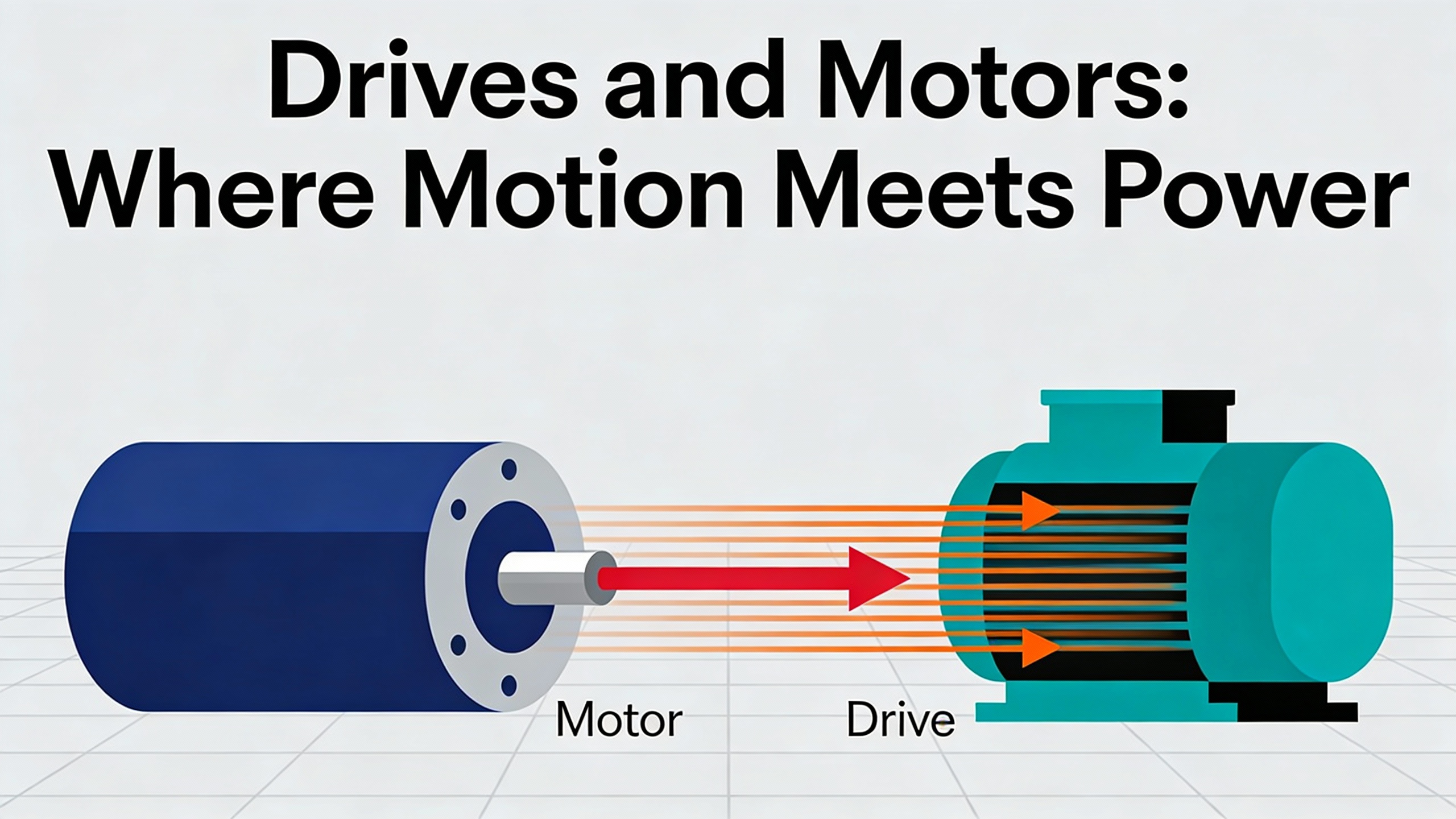
Drives and Motors: Where Motion Meets Power
The drive sits between the lowŌĆæpower world of the controller and the highŌĆæpower world of the motor. Motion Automation Intelligence describes it as the component that accepts lowŌĆævoltage control signals and converts them into the highŌĆæcurrent, highŌĆævoltage power that actually moves the motor. Medical Device & Diagnostic Industry adds that the drive must be matched to the motor type, both in topology and in how it commutates the phases.
Stepper drives, in their simplest form, use power transistors to sequence current through the motor phases in response to digital step and direction pulses. More advanced microstepping drives synthesize staircaseŌĆælike sinusoidal currents, which improves resolution and reduces resonance. Servo drives for DC brush motors typically use an HŌĆæbridge topology and take an analog command, such as a plus-or-minus voltage, then close current and velocity loops internally. Brushless servo drives use three halfŌĆæbridges and commutation logic based on Hall sensors or encoders, and may implement sinusoidal current control with phase advance for higher performance.
Motion Automation Intelligence distinguishes between linear and switching (PWM) drive architectures. Linear drives operate their transistors in the active region, which makes them quiet and suitable for lowerŌĆæpower applications but less efficient, so they dissipate more heat. PWM drives rapidly switch transistors fully on and off, achieving much higher efficiency and allowing more compact, easierŌĆætoŌĆæcool packages, at the expense of additional EMI and electrical noise. Medical Device & Diagnostic Industry notes that PWM drives now dominate for most applications, while linear drives still earn their keep when you must minimize EMI or interface with lowŌĆæinductance motors.
On the motor side, both sources align on a core taxonomy that is very relevant to industrial robots. Stepper motors are DC machines with multiple phased coils energized in sequence to produce discrete steps. Motion Automation Intelligence notes that they deliver precise, repeatable position increments, controllable speed, and strong lowŌĆæspeed torque. Medical Device & Diagnostic Industry highlights that steppers are particularly attractive in lowŌĆæcost openŌĆæloop applications where no feedback is required, which is why you still see them in lowerŌĆæend pickŌĆæandŌĆæplace machines or auxiliary axes.
Permanent magnet brush servomotors use a mechanical commutator and brushes. The MDDI guidance calls them mature, highŌĆæperformance devices, but also points out their limits: commutator wear, brush dust, arcing, and EMI/RFI issues. Brushless servomotors replace the mechanical commutator with electronic commutation. Motion Automation Intelligence explains that brushless servo motors deliver high acceleration and torque with reduced maintenance compared with brushed DC designs, while MDDI notes that they tend to have lower inertia, better thermal behavior, higher continuous torque and speed, and that advances in semiconductors have largely erased their historical cost disadvantage, leading them to dominate new designs.
Linear motors and linear servos deserve special attention for robotics. The MDDI article describes linear motors as conceptually ŌĆ£unrolledŌĆØ rotary motors, available in stepper, brush, brushless, and induction variants, that can replace mechanical elements like leadscrews or belts. They provide nonŌĆæcontact motion with high speed, high acceleration, cleanliness, and no performance loss over length, but they demand more expensive feedback, involve moving cables and exposed magnets that can raise safety and contamination concerns, and offer no simple gearing option beyond selecting a larger motor. Motion Automation Intelligence adds that linear servo motors avoid rotaryŌĆætoŌĆælinear conversion entirely, offering fast, precise, responsive motion with zero backlash and essentially no mechanical maintenance, at the cost of higher control bandwidth requirements and a larger physical footprint.
A simple example illustrates how these tradeoffs play out. Suppose you are adding a vertical ZŌĆæaxis to a robot for lifting fixtures. A stepper with a basic drive may be adequate if loads are modest, moves are intermittent, and losing position due to the occasional stall is acceptable. If the axis must hold variable loads precisely and recover quickly from disturbances, a brushless servo becomes compelling, thanks to its closed-loop torque control and better thermal performance. For a highŌĆæspeed inspection axis that must sweep smoothly over parts without mechanical backlash, a linear servo might justify its higher cost and footprint, provided your controller and feedback can support the required bandwidth.
From a power-system standpoint, all of these drives and motors reflect back into your electrical infrastructure. PWM drives in particular concentrate energy into switching harmonics, and groups of them starting or braking together can produce current surges. That is where coordinating drive tuning, protective device settings, and upstream power conditioning becomes important if you want robotic motion performance and UPS rideŌĆæthrough to coexist peacefully.
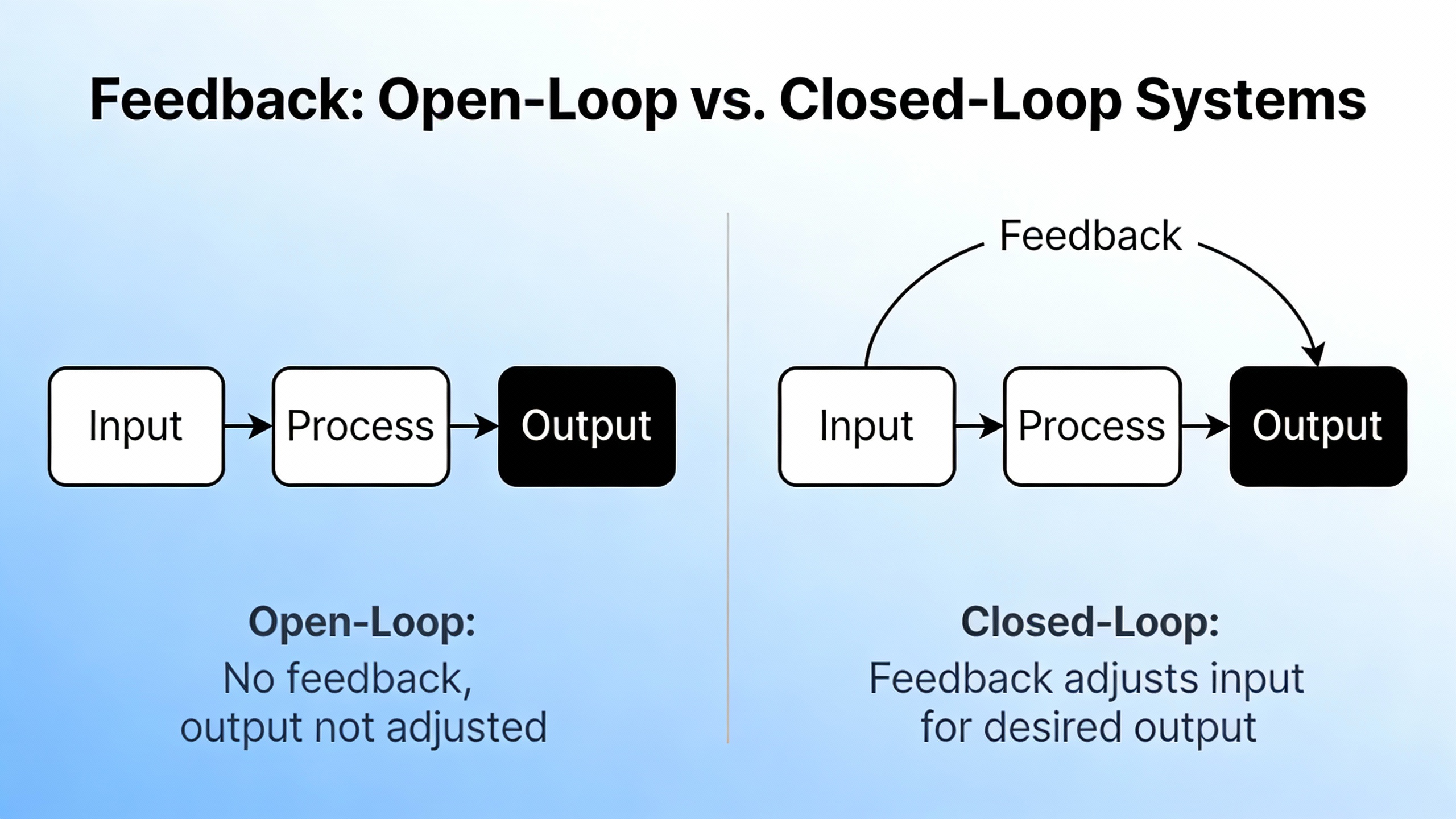
Feedback and the Choice Between Open-Loop and Closed-Loop
One of the most important strategic decisions in robotic motion control is whether each axis runs openŌĆæloop or closedŌĆæloop. The Motion Automation Intelligence article distinguishes openŌĆæloop systems, which do not use feedback, from closedŌĆæloop systems, which rely on feedback so the controller can adjust commands in real time for higher accuracy. Medical Device & Diagnostic Industry states this more concretely: feedback is mandatory for servomotors and optional for stepper motors.
Closed-loop systems rely on feedback devices, most commonly rotary or linear encoders, to report position, velocity, and direction back to the controller. Incremental encoders, as described in MDDI, output pulses proportional to position. By counting those pulses and differentiating over time, the controller infers both position and speed. HighŌĆæresolution encoders are favored when very smooth lowŌĆæspeed motion is required. Absolute encoders, as highlighted by Motion Automation Intelligence, provide unique position values that allow the system to track exact positions even after power cycles, which is especially valuable for robots that cannot easily reŌĆæhome safely.
Beyond encoders, the MDDI guidance lists resolvers, LVDTs, potentiometers, absolute and sinusoidal encoders, capacitive and inductive sensors, and laser interferometers as viable feedback options. The choice among these depends on required accuracy and repeatability, environmental conditions, temperature range, cost, and available space.
In a robotic cell, a practical pattern often emerges. Critical path axes that define tool tip position are almost always implemented as closed-loop servo systems with encoder feedback and update rates around one kilohertz. Less critical feeders or auxiliary axes may use steppers openŌĆæloop, particularly where the consequences of an occasional lost step are modest. The advantage of openŌĆæloop steppers, as both sources implicitly reinforce, is lower cost and simpler hardware. The tradeoff is that you cannot formally verify that the axis reached its commanded position, and you cannot automatically correct for load disturbances or wear.
As an example, picture a Cartesian robot with three main axes carrying the tool, and a small rotary axis carrying a simple reorienting motion. The three main axes are good candidates for closedŌĆæloop brushless servos with encoders, so that the controller can continuously coordinate their motion along complex paths. The rotary axis that simply flips a part ninety degrees might reasonably use an openŌĆæloop stepper, where any rare mispositioning can be detected by a downstream sensor or a simple check, without the cost of full feedback.
From a power protection angle, feedback loops add sensitivity to noisy or unstable supply conditions. Because the controller is updating currents based on precise feedback measurements at high rates, spurious noise from an underŌĆæfiltered supply or a poorly specified UPS can show up as jitter or hunting in the motion. That is why pairing feedback devices, drives, and any upstream power conditioning should be treated as a systemŌĆælevel design decision rather than three separate purchases.
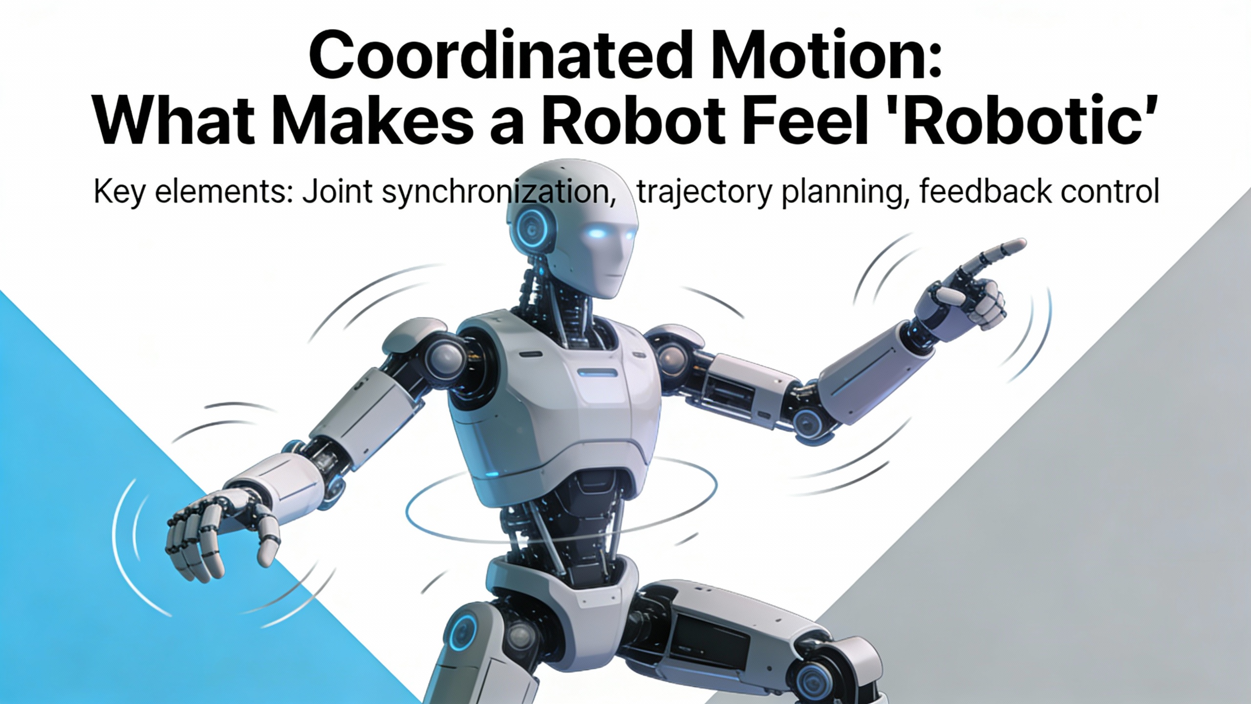
Coordinated Motion: What Makes a Robot Feel ŌĆ£RoboticŌĆØ
Real robotics is not about single axes moving in isolation. It is about multiple axes moving together, in a coordinated way, so that a tool tip, gripper, or sensor follows a continuous path at controlled speed. The MDDI article stresses that one of the first questions in motion design is whether axes must be coordinated, such as XŌĆōYŌĆōZ moving together, or can operate independently. It also lists support for coordinated motion features, including linear and circular interpolation, electronic gearing, and camming, as key criteria for choosing a controller.
Linear interpolation lets the controller move multiple axes so that the tool tip travels along a straight line through space. Circular interpolation does the same for arcs. Electronic gearing allows one axis to follow another with a defined ratio, mimicking mechanical gearing without physical shafts. Camming lets an axis follow a position profile as a function of another axis, as if it were riding on a virtual cam.
Consider a simple textbook example in an industrial context. A threeŌĆæaxis robot must move a vision camera from one corner of a pallet to the opposite corner in a straight line, maintaining constant speed for image capture. Without coordinated interpolation, you might program individual pointŌĆætoŌĆæpoint moves on each axis and hope they finish at the same time. The result is usually a path that resembles a staircase, with varying speed and small dwell points, making the images inconsistent. With coordinated motion, the controller computes synchronized trajectories so that at every millisecond servo tick, each axis moves just enough that the resulting tool tip path is straight and velocity is constant.
From a reliability advisorŌĆÖs viewpoint, coordinated motion also has implications for how you handle faults and power events. When axes are electronically geared or cammed together, a fault on one drive or a brief power disturbance that stops a single axis can throw the entire coordinated group out of alignment. Controllers with robust synchronization and errorŌĆæhandling features can detect such conditions and bring all axes to a controlled stop, rather than letting some continue while others stop abruptly. That graceful degradation is vital in preventing mechanical damage and reducing recovery time after power or drive issues.
Power and Reliability Considerations Around Drives and Control
Although the reference articles focus primarily on motion performance, they quietly contain several hints that matter a great deal for power system planning.
First, drives are power amplifiers. Both Motion Automation Intelligence and Medical Device & Diagnostic Industry describe them as devices that take lowŌĆævoltage control signals from a motion controller and convert them into highŌĆæpower motor currents and voltages. That simple description means drives are the primary interface between your robot and your power infrastructure. Their efficiency, cooling, and tuning determine how much real power and waste heat you must handle.
Second, PWM drives, which MDDI notes dominate in practice for their efficiency and compactness, work by rapidly switching transistors fully on and off. Motion Automation Intelligence points out that this approach is noisier than linear drives. That noise is not just acoustic; it includes electrical noise and EMI/RFI. Linear drives, which hold transistors in their active region rather than hard switching, generate less EMI/RFI but at the cost of efficiency and higher heat for a given load. From a power protection standpoint, that tradeoff turns into a question of whether you want higher efficiency and denser control cabinets with more switching noise, or lower noise and easier electromagnetic compatibility at the cost of higher power dissipation.
Third, both sources emphasize that drives must be tuned and set up to respect motor current limits and use the full dynamic range safely. Poorly tuned drives can command excessive current on aggressive moves or react poorly to feedback noise, which in turn causes nuisance trips on upstream protective devices or stresses shared power buses. Using modern digitally controlled drives with PCŌĆæbased configuration tools, as recommended in the MDDI article, is not just a convenience; it is also a way to systematically tune current limits, acceleration profiles, and fault thresholds so that motion performance and electrical protection settings are aligned.
In practice, when integrating robots, I often see two patterns. In systems where only the control logic and lowŌĆæpower electronics are placed behind a UPS or conditioned power source, drives are connected directly to wellŌĆæprotected plant power and are allowed to shut down on major events, relying on the controller to coordinate a clean restart. In other systems, certain critical axes, especially those holding heavy loads that must never drop, have both drives and controllers tied into a carefully sized and protected backup supply so they can hold position through short power interruptions. Either way, the starting point is always a clear budget of drive currents, anticipated motion profiles, and a realistic understanding of how drives will behave during and after power events.
A Practical Roadmap for Specifying Motion Control in a Robotic Axis
Bringing together the guidance from Motion Automation Intelligence and Medical Device & Diagnostic Industry, we can outline a practical, decisionŌĆæfocused roadmap for specifying motion control for a robotic application.
The starting point is to define the motion problem. Decide whether you are primarily controlling position, speed, or force, and whether accuracy or repeatability is more critical. Identify how many axes you have and whether they require coordinated motion or can move independently. A pickŌĆæandŌĆæplace robot sorting products into bins might demand repeatable positions and coordinated XŌĆōYŌĆōZ motion, while a simple indexing table feeding parts to a separate robot may only need independent, repeatable positions.
Next, select a motor and drive technology that match the mechanical and economic realities. If you need lowŌĆæcost motion and can tolerate occasional lost steps, a stepper motor with a microstepping drive can provide precise incremental motion and good lowŌĆæspeed torque without feedback. If you need higher top speeds, smoother lowŌĆæspeed motion, and better resolution, brush or brushless servomotors become attractive, as MDDI emphasizes, though they require more complex drives and feedback. For axes where eliminating mechanical backlash and maximizing responsiveness are paramount, linear servo motors can be compelling, provided you have room for their larger footprint and can justify the more expensive feedback and higher control bandwidth noted in both sources.
Then, choose a controller with the right coordination and integration capabilities. Make sure it supports the number and types of motors you plan to use, including any mix of stepper and servo axes. Evaluate its programming and diagnostics tools honestly against the skills of your team. Confirm that it provides coordinated motion functions such as linear and circular interpolation, electronic gearing, and camming, if your robot requires multiŌĆæaxis paths. Pay attention to its multitasking and errorŌĆæhandling capabilities, because those determine how well it will recover from power disturbances, drive faults, or sensor issues.
Finally, close the loop with feedback and power system design. Decide where feedback is mandatory, particularly on safetyŌĆæcritical or precision axes, and select feedback devices based on accuracy, environment, and space constraints, using the encoder and alternative sensor options outlined in the MDDI article as a menu. Ensure that your drive tuning, motion profiles, and upstream power protection are designed together, not in isolation. The aim is a system where the motion controller, drives, motors, feedback, and power infrastructure behave coherently under both normal operating conditions and abnormal events.
To see how this plays out in a real scenario, imagine you are retrofitting a palletizing cell with a new endŌĆæofŌĆæarm tool that adds a vertical adjustment axis for different box heights. The motion requirement is modest, but you want robust, repeatable positioning. You might decide that a stepper motor with a microstepping drive is sufficient mechanically. Because the axis is not safetyŌĆæcritical for holding heavy loads, you choose openŌĆæloop operation to keep costs down. Your existing motion controller can handle an extra stepper axis and does not need advanced interpolation for this motion. You connect the drive to your main robotic power panel, tune current limits conservatively using the vendorŌĆÖs digital configuration tool, and leave it outside the UPSŌĆæprotected control segment. In this way, you use closed-loop servos and protected power where they matter most and simpler, more economical motion elsewhere.
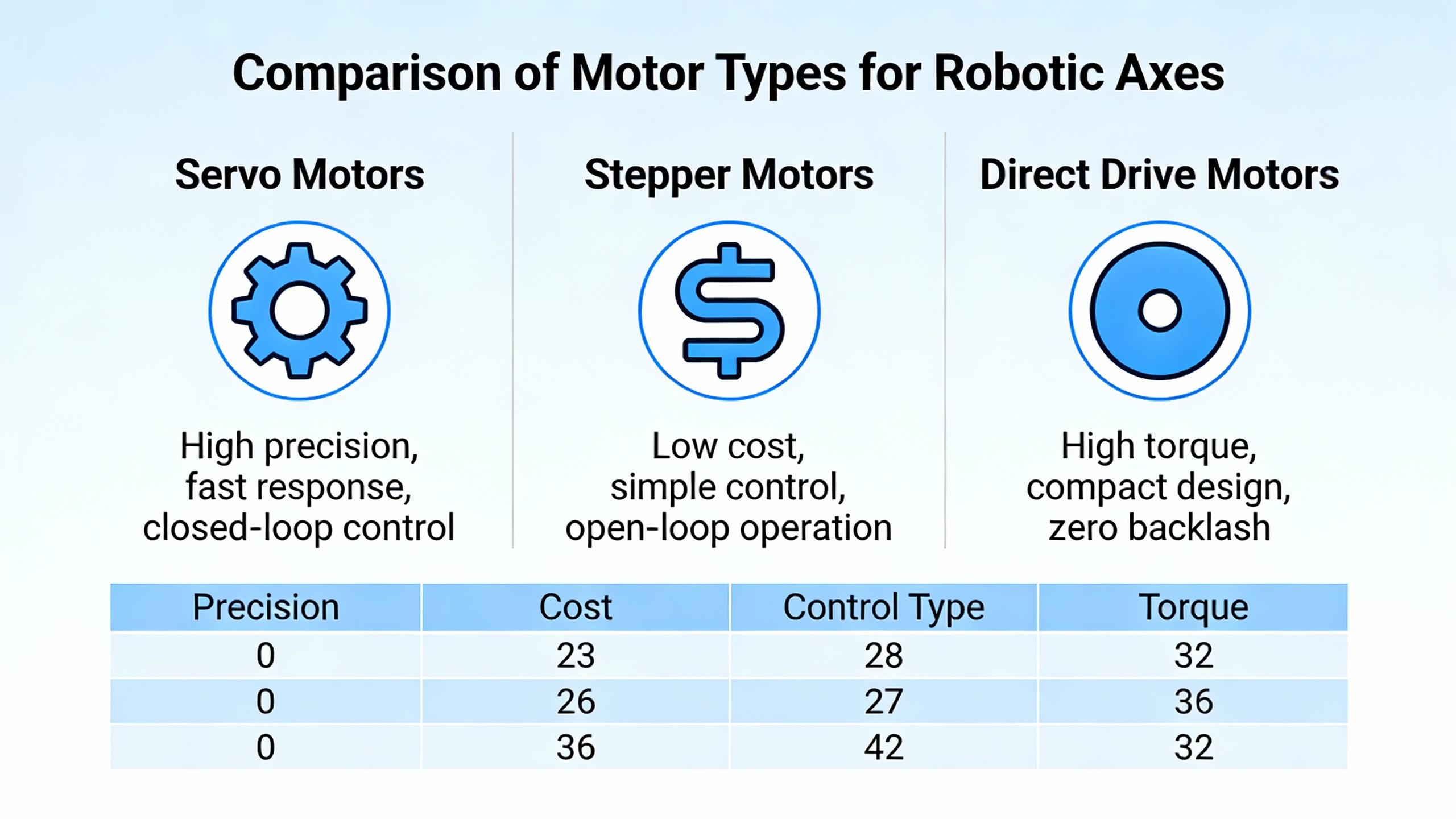
Comparison of Motor Types for Robotic Axes
The following table summarizes how the motor types described in the Motion Automation Intelligence and Medical Device & Diagnostic Industry materials align with common robotic needs.
| Aspect | Stepper Motor | Brush Servomotor | Brushless Servomotor | Linear Servo Motor |
| Basic behavior | Moves in discrete, repeatable steps with strong lowŌĆæspeed torque; often used openŌĆæloop | Uses mechanical commutator and brushes; mature, highŌĆæperformance torque source | Uses permanent magnet rotor and electronic commutation; low inertia, high torque and speed | Direct linear thrust without rotaryŌĆætoŌĆælinear conversion; nonŌĆæcontact motion |
| Typical use in robots | LowŌĆæcost axes where occasional lost steps are acceptable and loads are modest | Legacy or specialized axes where existing infrastructure favors brushed designs | Most new highŌĆæperformance axes needing smooth motion and feedback | HighŌĆæprecision, highŌĆæspeed linear axes where zero backlash and cleanliness matter |
| Pros highlighted in sources | Precise positioning in steps, controllable speed, strong lowŌĆæspeed torque | Established technology, good performance, straightforward drives | High acceleration and torque, better thermal behavior, reduced maintenance, dominant in new designs | Fast, precise, responsive motion, zero backlash, no mechanical maintenance, no loss of performance over length |
| Key drawbacks noted | No inherent verification without feedback, possible lost steps under overload | Brush wear, dust, arcing, EMI/RFI, maintenance needs | Requires more complex drives and feedback compared with steppers | Requires more expensive feedback, higher bandwidth control, larger footprint, moving cables and exposed magnets |
This table is not a substitute for detailed sizing, but it reflects the core pros and cons described in the reference material and provides a starting point for aligning motion technology with robotic axis roles.
Short FAQ
Do all robot axes need closed-loop servo control with encoders? Based on the guidance from Medical Device & Diagnostic Industry and Motion Automation Intelligence, servo axes do require feedback, but stepper axes do not. In practice, that means critical axes that define tool tip position or handle safetyŌĆæcritical loads are almost always implemented as closed-loop servo systems with encoder feedback and millisecondŌĆæscale servo updates. Auxiliary or lowŌĆærisk axes can sometimes use steppers in openŌĆæloop mode, trading away automatic error correction for lower cost and simpler hardware. The decision should be made axis by axis, based on the consequences of a positional error.
When is a linear motor worth the added complexity in a robot? The MDDI article and Motion Automation Intelligence both describe linear motors and linear servos as delivering nonŌĆæcontact motion with high speed, high acceleration, zero backlash, and no performance loss over length, but at the cost of more expensive feedback, higher control bandwidth, and safety considerations around exposed magnets and moving cables. In my experience, they are most justified on axes where mechanical backlash and compliance in belts or screws directly limit product quality or throughput, such as highŌĆæspeed inspection or precision dispensing. For general purpose pickŌĆæandŌĆæplace motion, rotary servos with mechanical conversion often remain more economical.
How should I think about drives and power protection together? Both reference sources emphasize that drives are highŌĆæpower devices that convert lowŌĆævoltage commands into motor currents and that PWM drives dominate thanks to efficiency and compactness, albeit with more noise. As a power and reliability advisor, I treat drives, feedback, and upstream power conditioning as parts of one system. HighŌĆædensity PWM drives can impose current surges and EMI on shared power buses, so their configuration, current limits, and braking behavior must be coordinated with breaker settings and any UPS or power conditioning you plan to use. Protecting controllers and critical feedback devices with stable, conditioned power, while designing clear, predictable behaviors for drives during power events, produces robotic cells that not only move precisely but also ride through realŌĆæworld disturbances gracefully.
Industrial robots only perform as well as the motion control and power systems that support them. When you align controller capabilities, drive and motor technologies, feedback strategies, and power protection into a coherent design, you move from merely ŌĆ£making the robot moveŌĆØ to building a coordinated, reliable motion platform that your production team can trust.
References
- https://www.academia.edu/114953575/Motion_Control_Systems
- https://en.wikipedia.org/wiki/Motion_control
- https://pmc.ncbi.nlm.nih.gov/articles/PMC11604719/
- https://dl.acm.org/doi/10.1145/3689299.3689309
- https://www.automate.org/motion-control/industry-insights/understanding-motion-control-basics
- https://www.plctalk.net/forums/threads/suggestions-for-motion-control-practice-hardware-and-projects.144436/
- https://www.limonrobot.com/motion-control-overview
- https://www.automateshow.com/blog/motion-control-101-fundamentals-and-emerging-trends
- https://www.controleng.com/motion-control-and-robotics-troubleshooting-and-maintenance-advice/
- https://www.mddionline.com/components/choosing-motion-control-components


 Videos
 News
News Applications


Leave Your Comment