Reliable power is not just about transformers, UPS systems, and inverters. In every plant I visit, the actual dayŌĆætoŌĆæday reliability often comes down to something less glamorous: how well the PLC wiring diagrams and panel drawings are designed, maintained, and used. When a UPSŌĆæbacked control system fails to start a critical pump or transfer a load, the team almost always ends up standing in front of a PLC panel with a stack of drawings in their hands.
This article looks at PLC wiring diagram standards and best practices from the perspective of industrial power and protection systems. Drawing on guidance from training providers such as AUSINET and ControlByte, reference articles from SolisPLC, Do Supply, PLC HMI, RW Instrumentation, and safetyŌĆæfocused works like Industrial Control Wiring Guide, the goal is to turn ŌĆ£paperworkŌĆØ into a frontline reliability tool for your UPSŌĆæfed and inverterŌĆædriven control systems.
Why PLC Wiring Diagrams Matter in PowerŌĆæCritical Systems
A PLC wiring diagram is essentially a map that connects your field devices, protection equipment, and power sources to the control logic. ControlByte describes electrical diagrams as graphical maps of the system, while Do Supply emphasizes that PLC panels act as the central node for machine control. In practice, this means that when a breaker trips, a UPS transfers, or a motor refuses to start, your ability to restore power hinges on how quickly you can navigate that map.
Several sources converge on the same point: proper PLC wiring and documentation underpin reliability, safety, and maintainability. PLC HMI and RW Instrumentation both stress that clean wiring and clear diagrams reduce noise problems, miswiring, and downtime. SolisPLC shows how panel wiring diagrams tie together everything inside a control panel, from main breakers and transformers to PLC I/O cards, drives, and safety relays. If those diagrams are incomplete or inconsistent, the risk of misdiagnosis rises sharply, especially when power quality events and control issues overlap.
From a powerŌĆæsystems standpoint, the stakes are higher around UPS and inverterŌĆæfed loads. A nuisance trip on a contactor feeding a small fan is annoying; a wiring error that leaves a UPSŌĆæbacked PLC unpowered during a transfer can shut down an entire process line. Electrical Engineering PortalŌĆÖs PLC wiring guidance makes it clear that factors like wire sizing, suppression of inductive loads, and shielding are not ŌĆ£optionsŌĆØ; they are integral design elements whose details must appear correctly in the diagrams for future technicians to understand and maintain them.
A simple example shows how diagrams affect decisions. Imagine a PLC controlling a 460 V threeŌĆæphase motor through a main breaker, a contactor, and an overload relay, with the PLC and control circuit powered from a 24 V DC supply derived through a transformer off the same bus, as described in SolisPLC examples. If the motor will not start, a technician with accurate diagrams can trace the threeŌĆæphase path, verify breaker settings, check the contactor coil supply, and confirm that the PLC output actually energizes the coil. Without diagrams that clearly separate the power and control circuits and annotate coil and contact references, that same investigation can take hours and involve trialŌĆæandŌĆæerrorŌĆöexactly the kind of downtime that good documentation is meant to prevent.
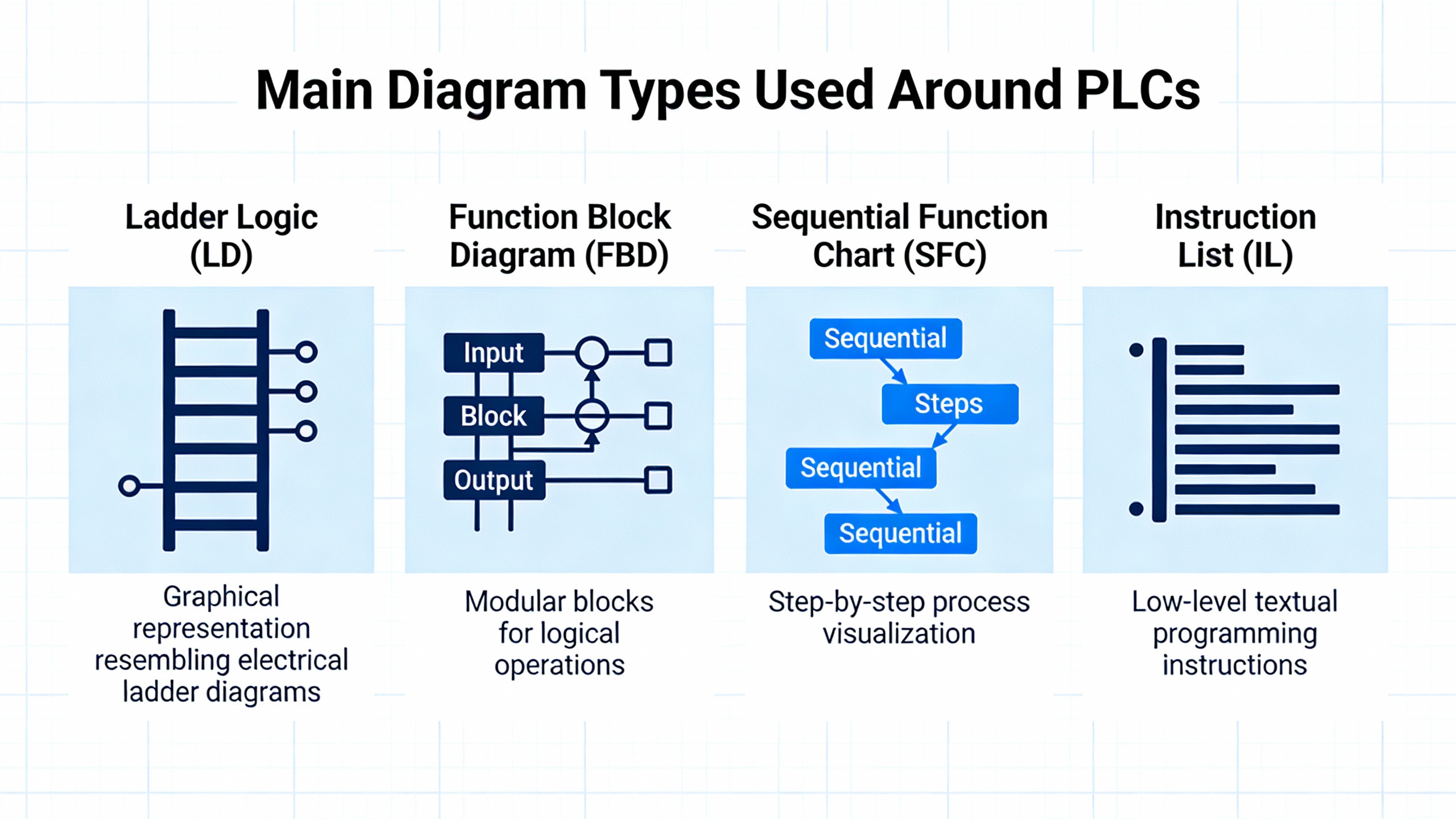
The Main Diagram Types Used Around PLCs
AUSINET and ControlByte both emphasize that you need to identify what kind of drawing you are looking at before you try to interpret it. PLC and industrial power systems usually rely on several diagram types that complement one another rather than one allŌĆæpurpose drawing.
AUSINET lists block diagrams, circuit or schematic diagrams, wiring diagrams, ladder diagrams, and singleŌĆæline diagrams. ControlByte describes diagrams as graphical maps showing components and current flow from simple lighting circuits up to complex automation. SolisPLC adds panel wiring diagrams and layout drawings that document every device and connection inside a control panel. Do Supply distinguishes between wiring diagrams, which show physical connections and terminal numbers, and schematics, which show logical relationships and functional paths.
In real projects, a powerŌĆæcritical PLC system will often use most of these views. A singleŌĆæline diagram might show the overall power distribution from utility to transformer, to UPS, to main switchboard and motor control centers. Panel wiring diagrams will show every breaker, power supply, PLC module, and terminal block inside each enclosure. Ladder diagrams will express the control logic that determines when breakers open, when static transfer switches move the load from utility to UPS, and when motor starters energize.
The table below summarizes the typical roles each diagram type plays around PLCŌĆæbased power and control systems.
| Diagram type | What it shows in practice | Where it helps most in PLC and power work |
| SingleŌĆæline diagram | Simplified power distribution: sources, transformers, main breakers, feeders | Understanding how UPS, inverters, MCCs, and panels tie into the power system |
| Block diagram | HighŌĆælevel blocks: PLC, UPS, drives, panels, networks and their interconnections | Explaining architecture to nonŌĆæspecialists and planning interfaces |
| Schematic/elementary | Logical circuits, symbols, contacts, coils, protective devices | Understanding control sequences and protection functions |
| Wiring diagram | Physical terminals, cable cores, wire numbers, routes, and junctions | Installation, maintenance, and field troubleshooting |
| Ladder diagram | PLC or relay logic as rungs between power rails, inputs on left, outputs on right | Reading and debugging PLC control programs and relay panels |
| Panel layout drawing | Physical placement: DIN rails, duct, components, spacing | Panel building, modifications, and thermal or accessibility assessments |
A practical example shows how these work together. Suppose you are qualifying a new UPSŌĆæbacked PLC panel that feeds several 460 V motor starters. You might begin at the singleŌĆæline diagram to confirm that the UPS output, transformer, and panel main breaker are properly coordinated. Then you turn to the panel wiring diagram to check that the UPSŌĆæderived 24 V DC control power is fused and landed correctly on the PLC power supply terminals. Finally, you open the ladder diagram or PLC printout to verify that the logic driving each motor starter aligns with the interlocks and safety circuits drawn in the schematics. Each diagram answers a different question, but together they tell the full story.
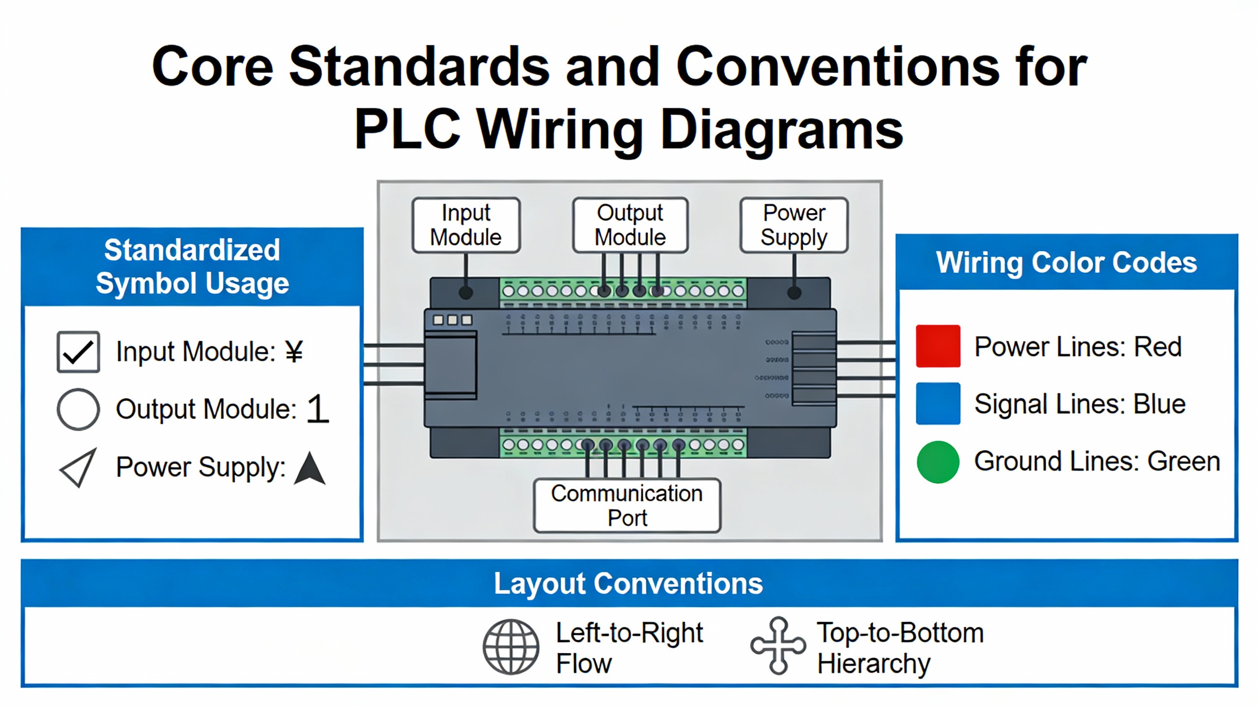
Core Standards and Conventions That Shape PLC Wiring Diagrams
One of the more useful insights from practicing engineers on EngŌĆæTips and EEVblog is that there is no single universal standard for PLC wiring diagrams. LadderŌĆætype schematics are common, but each firm tends to evolve its own conventions, particularly around wire numbering, line numbering, and tagging. Instead of searching for ŌĆ£the one true standard,ŌĆØ your aim should be to understand the common conventions and then apply them consistently across your own projects.
The Industrial Control Wiring Guide explains that formal regulations, such as the Health and Safety at Work framework and associated safety regulations, are mandatory, while standards like BS EN 60204 for machinery electrical equipment and BS EN 60947 or IEC 947 for lowŌĆævoltage switchgear are advisory documents used to demonstrate compliance. Components are often certified by bodies such as UL, CSA, and DIN/VDE to show they meet defined specifications. In the United States, SolisPLC emphasizes that panels must comply with the National Electrical Code, and individual states may adopt different NEC editions. In Australia and New Zealand, AUSINET references AS/NZS 3000 and AS/NZS 3017 for wiring and testing, as well as IEC 60617 for symbols.
For identification and structure, ControlByte points to IEC 81346ŌĆæ1, which encourages labeling each element by function, location, and product using consistent prefixes. Example tags include a function tag such as ŌĆ£=24VDC supply,ŌĆØ a location tag such as ŌĆ£+RG1ŌĆØ for a main switchboard, and a product tag like ŌĆ£ŌĆæM1ŌĆØ for a motor or ŌĆ£ŌĆæK2ŌĆØ for a relay. In large PLC systems with thousands of connections, this structured tagging helps technicians track which elements power the PLC, which cabinet or workstation they belong to, and which physical device is involved on each page.
EngŌĆæTips contributors describe line numbers as positional references along the ladder, often in steps of 10 or 100, and recommend tying wire numbers to these line numbers for better traceability. For example, wires on line 100 might be numbered 101, 102, and so on. Operator or coil numbers can appear to the right of the ladderŌĆÖs right rail to indicate which lines contain contacts controlled by that coil, while contact subscripts can reference the line number of the operating coil. This explicit linking of coil and contacts becomes invaluable when you are trying to trace why a downstream contact did not change state even though the PLC output apparently turned on.
AUSINET and Do Supply both stress the importance of systematic numbering and labeling in diagrams: wires W1 through Wn, motors M1 through Mn, and so on. SolisPLC adds a pageŌĆæandŌĆæcolumn system (such as 38.7 for page 38, column 7), which allows designers to show where a given symbol appears in multiple views. In practice, a field technician might find a device tagged ŌĆ£ŌĆæM1ŌĆØ on the wiring diagram, see a reference to ŌĆ£38.7,ŌĆØ flip to page 38, column 7 in the schematic set, and immediately locate the rung that controls it.
As an example, consider a UPSŌĆæbacked transfer breaker coil drawn on line 230 of a ladder diagram and tagged as coil ŌĆ£K230.ŌĆØ The associated contacts that feedback panel status to the PLC may be drawn on lines 310 and 320 with subscripts indicating ŌĆ£K230.ŌĆØ Wire numbers in this segment might be 231 and 232, reflecting their relationship to line 230. When a transfer fails, the technician can find coil ŌĆ£K230,ŌĆØ check whether the PLC output is energizing it, and then use the contact references and wire numbers to check the feedback path to the PLC input. Without these conventions, the same diagnosis would require more guessing, more time, and more risk.
Drafting PLC Wiring Diagrams: Best Practices That Stand Up in the Field
Once you understand the basic diagram types and conventions, the next step is ensuring that the diagrams you produce are actually usable in the field, especially when power and control issues are intertwined.
AUSINET recommends starting every drawing by clearly stating its purpose and identifying the diagram type. The title block and legend should spell out the symbol set, color conventions, and any nonŌĆæstandard practices. Do Supply also advises reviewing the title block, legends, and index before tracing circuits, so you understand the projectŌĆÖs I/O designation conventions, power distribution scheme, and safety notes. ControlByte points out that multiŌĆæpage diagrams need crossŌĆæreferences and potential lines labeled with voltage levels, such as 24 V DC and ground, particularly in multiŌĆævoltage systems.
One recurring theme across AUSINET, SolisPLC, Do Supply, EABEL, and PLC HMI is the clear separation of power and control circuits, both physically and on the drawings. AUSINET notes that industrial diagrams often separate power and control, sometimes using colorŌĆæcoded lines. SolisPLCŌĆÖs panel diagrams show threeŌĆæphase power circuits with bold lines, while thin lines indicate control and signal wiring, echoing Do SupplyŌĆÖs ladder examples where heavy lines show power flow and thin lines show control logic. EABEL and PLC HMI stress similar physical separation inside the panel, with power conductors in one duct and lowŌĆælevel control and communication wiring routed separately to limit interference.
On a drawing that supports a UPSŌĆæfed PLC panel, this means showing the main AC path from the UPS or transformer to the main breaker and down to the loads in a way that is visually distinct from the 24 V DC control rails feeding the PLC, safety relays, and I/O modules. It should be obvious at a glance which conductors carry highŌĆæenergy fault currents and which belong to sensitive control circuits.
Labeling and color coding are another area where practice and standards meet. AUSINET provides an example color scheme aligned with AS/NZS 3000 that differentiates active conductors, neutrals, and protective earth, as well as control and DC wiring. Electrical Engineering PortalŌĆÖs PLC installation guidance highlights durable labels for wires and terminal blocks, with color coding such as red for AC, blue for DC, and white for common in some schemes. PLC HMI and RW Instrumentation reiterate that every wire, connector, and terminal should be clearly identified using a labeling scheme that technicians can follow years later. EABEL adds that printed tags, ferrules, and a consistent labeling system for wires, terminals, and components pay off during troubleshooting and upgrades.
Wire sizing, routing, and noise control matter just as much as symbol choices. Electrical Engineering Portal notes that each I/O terminal has an allowable wire gauge and current rating and insists that conductors must match the specified size to carry the maximum possible load safely. The same source recommends grouping conductors for a given I/O module into bundles while keeping input, power, and output bundles in separate ducts to reduce interference. PLC HMI and RW Instrumentation both stress physical segregation of highŌĆævoltage and lowŌĆævoltage wiring, and using shielded cables for analog or communication signals. Electrical Engineering Portal goes further for lowŌĆælevel signals, recommending separate wireways and twisted shielded cable with about a 1ŌĆæinch lay, roughly 12 twists per foot, with shields grounded at one end only to prevent ground loops.
A simple noiseŌĆærelated example illustrates why these details must show up on the drawings. Suppose you have a 100ŌĆæfoot run of analog 4ŌĆō20 mA wiring from a flow transmitter back to a PLC located in a UPSŌĆæbacked panel, sharing a tray with 460 V motor feeder cables. If the wiring diagram shows that the analog cable is shielded, twisted, and its shield is grounded only at the panel end, a technician diagnosing noisy readings can quickly confirm the installation matches the drawing. If the diagram is silent about shielding and separation, installers may run the cable alongside motor feeders without twisting or proper shielding, and the next operator ends up chasing phantom flow fluctuations caused by induced noise.
Grounding, shielding, and power quality are particularly important where PLCs live alongside UPS systems and inverters. EABEL recommends a dedicated grounding busbar inside the panel with all grounds connected to that single point to avoid ground loops and stabilize signal integrity, and also advises grounding shields at one end only, typically at the PLC side, while bonding the panel enclosure to earth for fault protection. Electrical Engineering Portal and PLC HMI echo that shielded cables should generally be grounded at one point only, often at the rack chassis. For power quality equipment such as UPS systems and drives, SolisPLC stresses that each power bus, such as a 575 V AC bus and a 24 V DC control bus, should be clearly identified at its source, with appropriate fusing and gauge selection documented on the diagram.
Protection around inductive loads is another area where diagrams must reflect design intent. Electrical Engineering Portal warns that inductive loads like relays, solenoids, and contactors can generate voltage spikes of several thousand volts when turned off, which can cause erratic PLC operation or damage outputs. The guidance recommends RC snubbers across small AC loads, combinations of metalŌĆæoxide varistors and RC networks for larger contactors, and freeŌĆæwheeling diodes across DC loads. It also notes that while some PLC output modules include builtŌĆæin suppression, external components may still be required. SolidŌĆæstate outputs should be protected with correctly rated fuses, sometimes built into the module, otherwise installed near the terminal blocks. SolisPLC reinforces the need for separate fuses for sensitive loads such as variable frequency drives.
From a reliability advisorŌĆÖs perspective, these suppression components must appear explicitly on the diagrams, with ratings and part numbers where practical. When a PLC transistor output fails in a panel that also contains UPSŌĆæfed control circuits, one of the first questions should be whether every inductive load on that output path has the proper snubber or diode installed as drawn.
Pneumatics bring their own set of best practices inside PLC panels. A Control.com discussion describes the temptation to mount stacks of pneumatic valves inside small PLC control panels near the process for compactness and convenience. Practitioners in that forum warn that allowing compressed air to exhaust inside the enclosure can introduce oil and moisture, contaminating electronics, degrading insulation, and increasing shock risks. Even valves with external exhaust ports may have poorly documented pilot exhaust paths that still vent into the cabinet. Good practice in that discussion is clear: if valves must be mounted inside an electrical enclosure, exhaust should be piped outside the box, and ancillary pneumatic hardware such as filters, regulators, dump valves, and lockouts should be installed outside the enclosure so they can be serviced safely without opening live electrical equipment. Diagrams should reflect this by clearly indicating any pneumatic penetrations and external exhaust routing.
In many powerŌĆæcritical installations I have reviewed, the cleanest PLC wiring diagrams are the ones that treat all of these elementsŌĆöspacing, segregation, shielding, suppression, labeling, and even pneumaticsŌĆönot as ŌĆ£extrasŌĆØ but as design requirements that must be documented just as rigorously as breaker sizes and cable types.
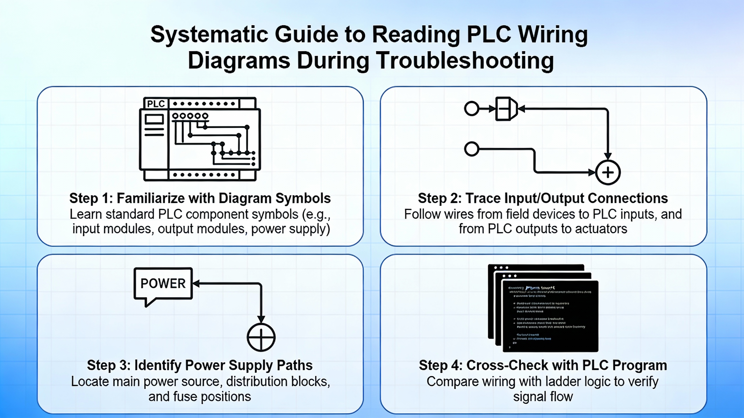
Reading PLC Wiring Diagrams Systematically During Troubleshooting
Writing standards and best practices into your diagrams is only half the story. The other half is having a disciplined method for reading those diagrams when something goes wrong.
AUSINET recommends starting by identifying the diagram type and purpose, then following power flow from the source through the circuit to trace operation and locate faults. ControlByte advises starting with simple diagrams and working up to full industrial drawings, making use of crossŌĆæreferences and potential lines to see how different voltage levels and pages connect. Do Supply suggests a practical method specifically for PLC wiring: begin at the field device tag, follow the conductor and cable numbers back to the panel terminal strip, then to the I/O card terminal, and finally map that channel to its PLC address and rung in the logic. SolisPLC-style documentation often supports this by dedicating one drawing page per PLC card, showing each field device wired to each specific I/O point.
Safety must stay in front of mind. Do SupplyŌĆÖs material emphasizes verifying power isolation with proper test instruments, following lockout and tagout procedures, respecting arcŌĆæflash boundaries, and never relying solely on drawings to assume conductors are deŌĆæenergized. The Industrial Control Wiring Guide adds that safe working practices and PPE are mandatory, and that workers should know how to isolate electrical supplies and respond to electric shock or fire events.
A systematic reading approach might go like this in practice. Suppose an operator calls because a 0.75 hp threeŌĆæphase motor on a UPSŌĆæbacked process skid will not start. SolisPLC presents a representative motor starter circuit where a 460 V threeŌĆæphase bus feeds a motor contactor and disconnect, with feedback contacts wired to PLC inputs. With the diagrams in hand, you first verify that the main 460 V bus is live using the singleŌĆæline and panel wiring diagrams to locate the correct test points. Next, you examine the motor starter schematic to identify the control circuit: the PLC output driving the contactor coil, any interlocks, and the feedback contacts. Then you go to the PLC I/O card page to find exactly which terminal and address the coil output uses, and which input terminals carry the status feedback.
At this point, you can energize a manual start command (under safe conditions) and measure whether the PLC output terminal actually delivers 24 V DC to the coil when the rung is true. If the coil is not energized, you turn to the ladder diagram or PLC logic printout and see which rung controls that output, checking interlocks like EŌĆæStops and safety relays that may be preventing it from turning on. If the coil is energized but feedback never reaches the PLC, you trace that feedback circuit using the same device tags and wire numbers. The diagrams transform what could be a blind search into a structured sequence of checks.
The same method applies to UPS and transformer issues. If a PLC panel loses 24 V DC control power intermittently, SolisPLCŌĆÖs examples of transformers and power supplies feeding separate control buses, combined with Electrical Engineering PortalŌĆÖs instructions on grounding and shielding, let you trace the control power path from the AC source through the transformer, fuses, and power supply to the PLC. With that information, you can identify whether the issue lies in primary protection, in the power supply itself, or in downstream wiring.
When systematically applied, this style of navigation becomes second nature and is particularly powerful when combined with good annotation. Engineers on EngŌĆæTips mention that clear annotations of ladder and logic allowed one practitioner to remotely reproduce a PLC circuit, locate a logic bug, and direct a simple jumper insertion that brought a plant back online within about an hour. That level of remote troubleshooting is only possible when the diagrams reflect reality and follow consistent standards.
Documentation, QA, and the Lifecycle of PLC Wiring Diagrams
PLC wiring diagrams are not static artifacts; they evolve as your process changes and as you add new UPS systems, drives, or protection equipment. Several sources emphasize that documentation quality and maintenance are as important as technical correctness on day one.
AUSINET and ControlByte recommend modular organization of drawings, clear legends, and explicit revision dates. PLC HMI, RW Instrumentation, and Electrical Engineering Portal all treat documentation and labeling as integral design elements, not afterthoughts. RW Instrumentation in particular stresses maintaining comprehensive documentation, including current wiring diagrams, cable specifications, component lists, layout diagrams, and records of all modifications, so that future troubleshooting and upgrades are informed by accurate information rather than guesswork.
EABEL focuses on precise installation and thorough testing of completed panels. It recommends carefully marking and mounting DIN rails, placing devices according to the layout drawing, maintaining spacing for airflow and wiring, and securing all components against vibration. After wiring, EABEL advises checking supply voltages, loading and testing the PLC program, simulating I/O with test signals, and confirming that safety functions such as emergency stops and interlocks operate correctly. Electrical Engineering PortalŌĆÖs PLC wiring guidelines add specific checks such as continuity tests, pullŌĆætesting terminations, and insulationŌĆæresistance checks where applicable.
Formalized testing such as Factory Acceptance Tests is another step where diagrams play a central role. EABEL suggests that FAT results, upŌĆætoŌĆædate schematics, and change logs be documented together so that any deviation from design is captured and traceable. PLC HMI and RW Instrumentation both highlight the value of regular inspections and periodic reviews of wiring, including updating diagrams when changes are made in the field. In my experience on power projects, some of the most expensive outages have been caused not by initial design errors but by undocumented ŌĆ£quick fixesŌĆØ that technicians applied during night shifts, which never made it onto the drawings.
On the tools side, PCSCHEMATIC Automation is one example of electrical design software that helps enforce standards by embedding component vendor data into symbols, automatically generating project lists, managing wire numbering, and creating crossŌĆæreferences through signal symbols. It allows designers to copy regions of a diagram, automatically renaming symbols to avoid conflicts, and to apply consistent properties such as font size or color across objects. EEVblog forum contributors also mention tools such as SEE Electrical, WSCAD, and DesignSpark Electrical for different scales and budgets. Regardless of the chosen package, the common thread is using CAD features such as automatic wire numbering, gridŌĆæbased symbol placement, templates, and subdrawings with article data to keep diagrams consistent across projects.
A concrete lifecycle example illustrates the value of this discipline. Consider a tenŌĆæyearŌĆæold PLC panel that was originally built with a conventional power supply and later retrofitted with a UPSŌĆæfed DC bus. If the retrofit is properly documented, the panel wiring diagrams will show the UPS input, the new DC distribution, the updated protective devices, and any changes to PLC power feeds, all with revised revision dates. The next time a PLC brownout occurs during a transfer, technicians can see exactly which part of the control power path is new, which protective devices protect it, and where to measure first. If the retrofit was done informally and never updated in the documentation, the same event might trigger hours of confusion as they discover previously unknown connections and unmarked jumpers.
Training and culture complete the picture. ControlByte and AUSINET both encourage ongoing training in reading and designing electrical diagrams, sometimes including courses where participants design their own control cabinets from sample diagrams. PLC HMI and RW Instrumentation similarly call for training operators and maintenance personnel in PLC wiring principles, safety practices, and documentation standards. In powerŌĆæcritical environments, that level of literacy around wiring diagrams is as essential as knowing how to operate the UPS itself.

Brief FAQ on PLC Wiring Diagram Standards
Is there a single ŌĆ£correctŌĆØ standard for PLC wiring diagrams in industrial control?
Practitioners on EngŌĆæTips and EEVblog agree that there is no single global standard for PLC wiring diagrams. Instead, there are families of practices shaped by regional standards, such as NECŌĆæoriented ladder diagrams in the United States and IECŌĆæstyle diagrams in Europe, along with formal standards like IEC 81346ŌĆæ1 for tagging and BS EN 60204 for machinery electrical equipment. Within those frameworks, most plants adopt companyŌĆæspecific conventions for line numbers, wire numbers, and symbol usage. The best approach is to align with the applicable national and industry standards, then define a clear internal drawing standard optimized for troubleshooting and stick to it across all projects.
How much detail should a PLC wiring diagram include around power quality and protection?
Sources like SolisPLC, Electrical Engineering Portal, PLC HMI, and RW Instrumentation converge on a simple rule: include enough detail that a qualified technician can safely understand and troubleshoot the system without guesswork. For power and protection, that means showing power sources such as transformers and UPS outputs, main and branch overcurrent devices, transformers and power supplies for control circuits, grounding and bonding points, surge protection, suppression around inductive loads, and safety circuits involving EŌĆæStops and safety relays. If a device or connection affects whether the PLC stays powered and whether a fault clears safely, it belongs on the diagram.
How should pneumatics be shown when pneumatic valves are mounted in PLC panels?
The Control.com discussion on pneumatic valves in PLC enclosures highlights that, where pneumatics and electrics share a cabinet, exhaust routing and maintenance responsibilities become critical. Good practice is to show pneumatic valve manifolds, their solenoid wiring, and any exhaust piping that leaves the enclosure on the diagrams, clearly indicating that exhaust is not vented inside the electrical cabinet. Ancillary pneumatic hardware such as filters, regulators, and lockout valves should normally be installed outside the electrical enclosure and drawn accordingly. This not only reduces contamination risks but also avoids situations where pneumatic maintenance staff must open energized electrical cabinets, which many facilities do not permit.
A wellŌĆædesigned PLC wiring diagram is more than lines and symbols; it is a reliability blueprint for how your control, protection, UPS, and inverter systems behave in the real world. When your standards are clear, your diagrams are consistent, and your teams are trained to use them, you gain the ability to diagnose power and control problems quickly and confidently, rather than fighting both the fault and the documentation at the same time.
References
- https://www.academia.edu/8271030/Industrial_Control_Wiring_Guide
- https://abe.ufl.edu/faculty/tburks/Presentations/ABE5152/Electrical%20Symbols%20and%20Line%20Diagrams.pdf
- https://www.plctalk.net/forums/threads/electrical-wiring-diagrams-us-standards.52001/
- https://electrical-engineering-portal.com/electrical-design-plc-panel-wiring-diagrams
- https://accautomation.ca/testing-and-wiring-plc-digital-inputs/
- https://ausinet.com.au/how-to-read-interpret-electrical-wiring-diagrams/
- https://www.eabel.com/plc-panel-design-safety-layout-best-practices/
- https://radicasoftware.com/blog/accuracy-in-electrical-panel-design-leveraging-electrical-cad-software
- https://www.solisplc.com/tutorials/electrical-panel-wiring-diagram
- https://control.com/technical-articles/electrical-drawings-schematics-and-wiring-diagrams-how-to-read-them/


 Videos
 News
News Applications


Leave Your Comment