In industrial and commercial facilities, pumps are some of the largest continuous electrical loads on the bus. As a power system specialist who spends a lot of time in mechanical rooms and electrical rooms, I see the same pattern over and over: pumps running at full speed against throttled valves, wasting energy and beating up mechanical equipment, while a variable frequency drive (VFD) sits unused on a wish list instead of on the wall.
A properly engineered VFD on a pump is not just an energy gadget. It is a power conversion system, very similar in topology to a double-conversion UPS, that reshapes how the motor draws power from the electrical system and how the pump delivers flow to the process. When you match the drive, motor, and pump correctly and maintain them with discipline, you can cut energy use dramatically, improve power quality, and extend equipment life. When you get it wrong, you inherit nuisance trips, harmonics issues, overheated motors, and stranded assets.
This article focuses on VFDs for pump applications and is organized around three practical questions plant engineers and facility managers should answer before they buy or retrofit a drive on a pump.
How VFDs Transform Pump Energy Use
From throttle control to smart power conversion
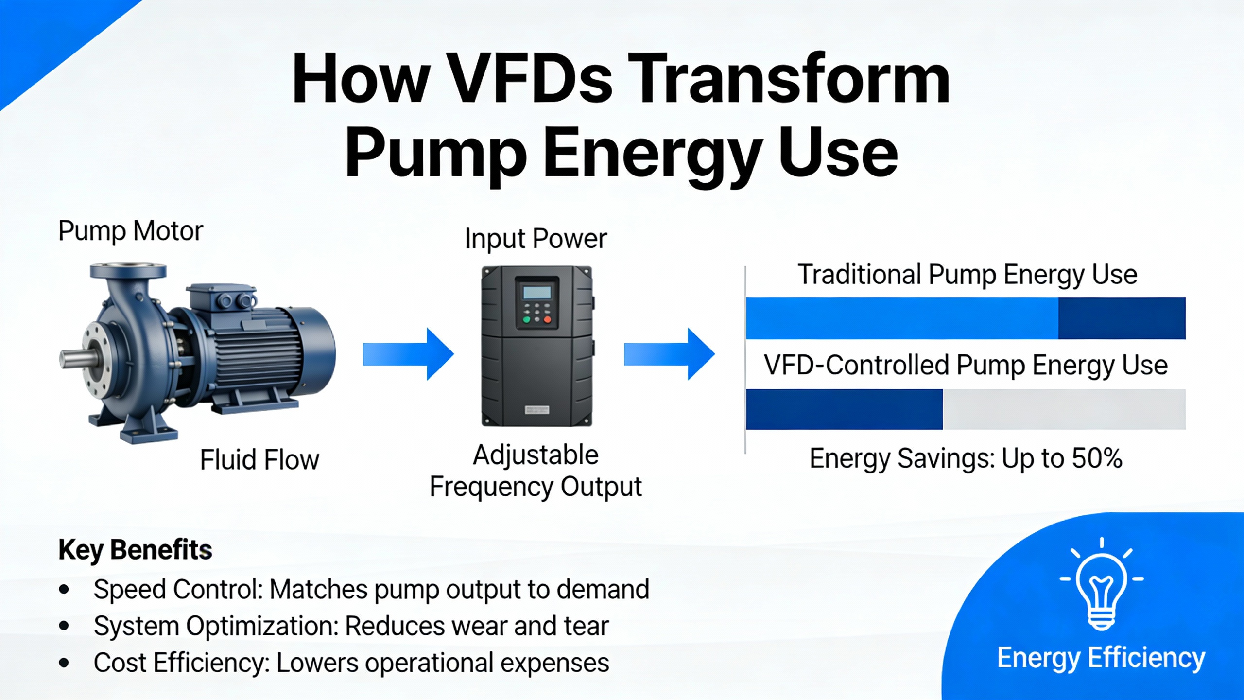
Before modern VFDs, engineers controlled pump flow with throttling valves, bypass lines, and mechanical devices such as hydraulic couplings or variable pitch sheaves. Electrical Engineering Portal and Control Engineering both note that these methods waste energy because the motor still runs at fixed speed while the system throws away excess head across a valve or bypass.
A VFD changes that model. As described in Electrical Engineering Portal and Control Engineering, a typical three-phase drive has three power stages: a rectifier that converts incoming AC to DC, a DC link or bus that smooths and stores energy, and an inverter that reconstructs a variable-frequency, variable-voltage waveform for the motor using pulse width modulation (PWM). The control electronics adjust the motorŌĆÖs supply frequency and voltage in real time so pump speed matches process demand instead of running flat-out all the time.
Consulting-Specifying Engineer points out that this topology is almost identical to a double-conversion UPS; the difference is in the inverter control philosophy. A UPS tries to hold voltage and frequency constant regardless of load, while a VFD deliberately varies voltage and frequency while roughly maintaining current to control speed and torque. That is why VFDs are rated primarily by current, not kVA.
On the hydraulic side, the advantage is that centrifugal pumps are inherently variable-torque loads: torque and power fall rapidly as speed drops. Control Engineering reports that when you slow a centrifugal pump with a VFD instead of throttling it, energy savings can reach roughly 60 percent in favorable cases, and pumps.org emphasizes that this is especially true in friction-head-dominated systems with frequent load swings.
Affinity laws and a simple pump energy example
The engineering reason for those savings is captured by the pump affinity laws. Consulting-Specifying Engineer uses a simple example: for a centrifugal pump driven by an induction motor, flow is roughly proportional to shaft speed, head is proportional to speed squared, and power is proportional to speed cubed. In practical terms, that means a modest speed change yields a much larger power change.
Consider a 100 hp pump operating at about 1,750 rpm at design conditions. If your process often needs only half of that flow, you could run the pump at roughly half speed instead of throttling. Using the cube relationship highlighted in Consulting-Specifying Engineer, the power required at half speed is approximately 12.5 hp. You have gone from feeding a 100 hp load to feeding a 12.5 hp load at the motor shaft for that portion of the operating hours.
Control Engineering cites real-world savings for centrifugal pumps of up to about 60 percent when VFDs replace throttling. Processing-focused guidance summarized by various engineering sources indicates many projects land in the 20 to 50 percent savings range once you account for actual load patterns, pump curve limits, and minimum speed constraints. Even if your duty cycle is modest, those reductions add up quickly on large pump motors that run thousands of hours per year.
There is another side benefit: starting and stopping. Pumps.org notes that a VFD typically limits starting current to around 150 percent of full-load current, compared with 500 to 600 percent inrush for across-the-line starting. Soft electrical starting means less voltage dip on the bus, less stress on upstream breakers and transformers, and far less torsional shock on the pump shaft, couplings, and piping.
Which Pump Applications Actually Benefit from VFDs?
Centrifugal pumps: variable torque and big gains
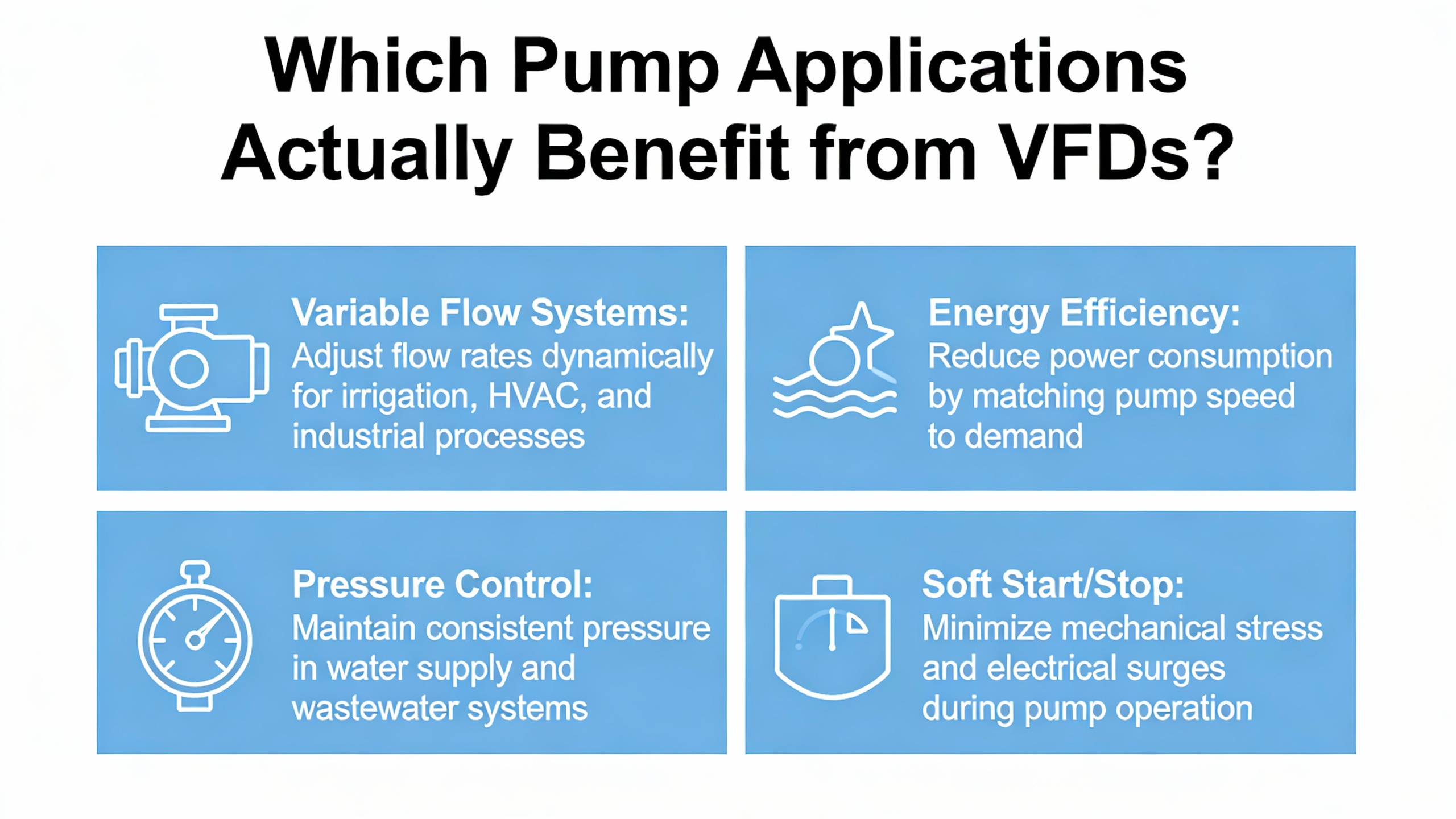
From a driveŌĆÖs perspective, the first question is load type. AutomationDirect and Hitachi explain that pumps and fans are normally treated as variable-torque loads, while conveyors and positive displacement machines are constant-torque. Pumps.org refines that further for pump systems by distinguishing rotodynamic (centrifugal) pumps from positive displacement designs.
Centrifugal pumps are the classic VFD success story. Their torque demand drops with the square of speed, and they rarely need full torque except near design speed. Control Engineering notes that these loads are actually difficult to overload when applied correctly with a VFD. That is why most drive manufacturers publish a ŌĆ£variable torqueŌĆØ rating that allows slightly higher horsepower for the same current frame when the load is a fan or pump.
Imagine a chilled water pump in a high-rise, serving variable flow air-handling units. During mild weather or partial occupancy, the system might only need 40 percent of design flow most of the day. With a constant-speed pump and throttling valves, the motor still spins at synchronous speed while the valve wastes head. With a VFD holding differential pressure with its built-in PID loop, the drive drops speed to match the actual flow demand. As PumpWorks and Pumps.org emphasize, this not only saves energy, it stabilizes pressure, reduces cavitation risk, and reduces noise and vibration in the piping network.
Positive displacement pumps: constant torque and caution
Positive displacement pumps are different animals entirely. The Control.com engineering forum notes that Mono-type progressive cavity pumps, gear pumps, and many other positive displacement designs need high torque at any speed, including low speed. They can develop their full discharge pressure even when turning slowly, which is the exact opposite of centrifugal behavior.
Because of this, Control.com contributors strongly recommend specifying constant-torque or heavy-duty rated VFDs for positive displacement pumps, not the lighter variable-torque drives typically used on centrifugal pumps. The drive must be capable of delivering full rated motor torque continuously and short-term overload up to around 200 percent of torque for a few seconds without tripping, so it can start and accelerate the pump under worst-case conditions.
If you undersize the drive by picking a variable-torque model based only on horsepower, you risk a pump that stalls or never reaches speed under load, or a drive that nuisance-trips on overcurrent. More importantly, you can lose the protection you think you have: a constant-torque-rated drive provides more robust current limiting, while a marginally sized variable-torque drive may not respond fast enough to abnormal torque rises, such as a blocked discharge line.
Pumps.org and Control Engineering both warn that positive displacement pumps under VFD control should be analyzed carefully for startup and low-speed conditions. It is good practice to ensure any bypasses or relief paths are available during ramp-up and to define minimum safe speeds and maximum duration at high torque, then encode those limits in the driveŌĆÖs parameter set.
Speed limits, motor cooling, and resonance
Even with centrifugal pumps, you cannot treat speed range as infinite. Consulting-Specifying Engineer reminds us that most pump motors are totally enclosed fan-cooled (TEFC), with a shaft-mounted fan providing cooling air. When a VFD slows the shaft, it also slows the cooling fan. Heat generated in the motor windings has less airflow to carry it away.
The same article cites a widely used rule of thumb: every increase of about 18┬░F in winding temperature cuts insulation life roughly in half, and every similar decrease can double it. That effect exists whether the motor is on a VFD or not, but long runs at low speed under VFD control make it far more likely that you will accumulate hours at elevated temperature. Motor manufacturers publish allowable speed ranges for their TEFC motors; they often permit certain low-speed operation at reduced load, but expect designers to respect those limits.
Pumps.org also flags structural resonance as a risk. Variable-speed operation can pass through torsional or structural natural frequencies of the motor-pump-base assembly. If a VFD-controlled pump spends a lot of time in a resonant speed band, vibration can escalate and damage bearings, welds, and piping. The Hydraulic InstituteŌĆÖs guidance (such as ANSI/HI 9.6.8) helps owners and OEMs identify and avoid those speeds. In practice, you define ŌĆ£no-goŌĆØ or ŌĆ£skipŌĆØ speed bands in the drive and tune PID loops so the system does not hunt around a resonance.
The practical takeaway is simple. As you consider whether a pump is a good VFD candidate, you should identify the load type, required speed range, motor cooling limitations, and any resonance concerns up front. Treat those as hard constraints when you specify both the drive and the control strategy.
Selecting the Right VFD and Motor for Pumping Duty
Match the drive to the motor and torque profile
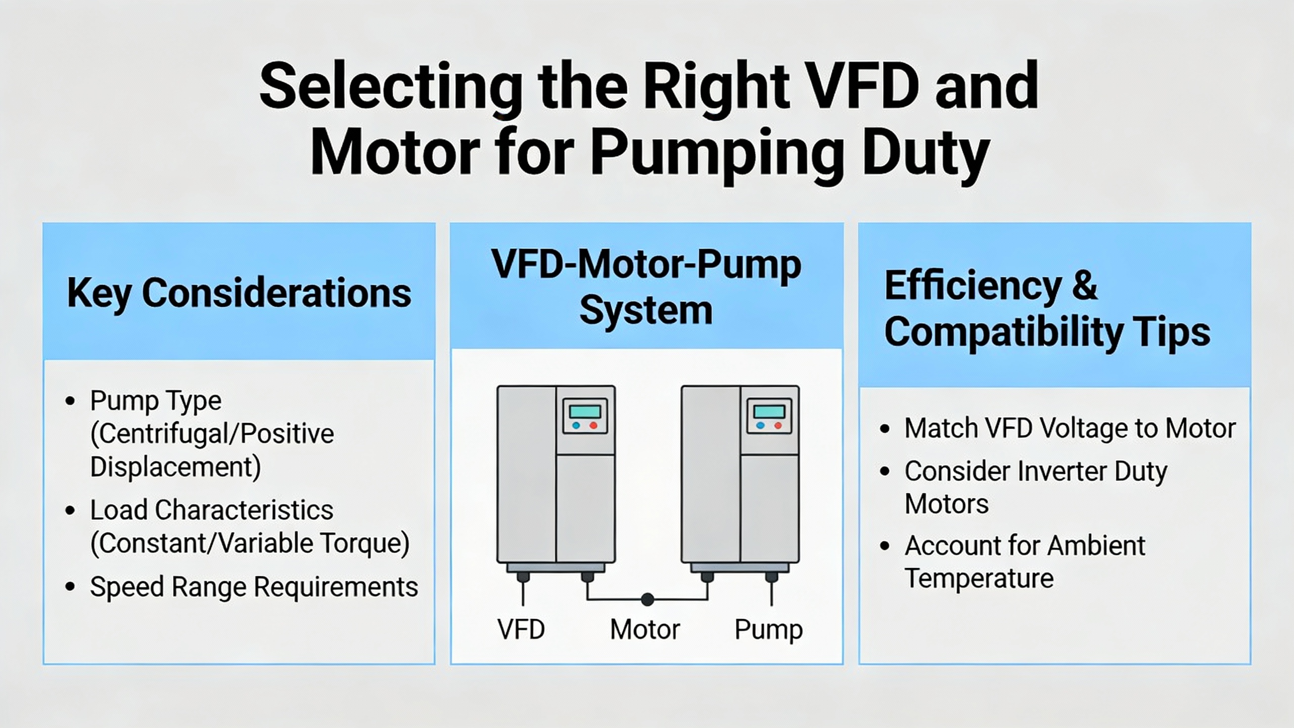
AutomationDirect stresses that you should never size a VFD by horsepower alone. The critical data are on the motor nameplate: voltage, phase, and full-load amperage (FLA). HitachiŌĆÖs application guidance adds that the driveŌĆÖs output voltage and phase must match the motorŌĆÖs, and the driveŌĆÖs current rating should be equal to or slightly higher than the motor FLA. If the drive takes single-phase input while feeding a three-phase motor, the manufacturerŌĆÖs derating rules must be applied, because most drives are significantly derated on single-phase supply.
For pumps, you then match the driveŌĆÖs torque rating to the application. AutomationDirect and Control Engineering explain that drives have variable-torque ratings for fans and centrifugal pumps, and constant-torque ratings for conveyors, hoists, and positive displacement machines. If your pump is centrifugal and never sees high torque at low speed, its variable-torque rating may be appropriate. If it is positive displacement or otherwise behaves like a constant-torque load, default to the constant-torque rating, even if that means choosing a physically larger drive.
Overload is the next piece. AutomationDirect notes that many general-purpose drives are designed for about 150 percent overload for up to sixty seconds. If your pump frequently starts under heavy load or can see transient blockages, you may need to oversize the drive frame or select a heavy-duty rating that allows for higher or longer overloads. Control.comŌĆÖs guidance for progressive cavity pumps goes further and looks for drives capable of up to roughly 200 percent torque momentarily.
Modern drives also offer different control methods. Hitachi, for example, offers simple scalar (V/f) control and more advanced sensorless vector control. Scalar control maintains a fixed volt-per-hertz ratio and is adequate for most centrifugal pumps that do not need high torque at low speed. Sensorless vector control does a better job of separating flux and torque components, yielding higher starting and low-speed torque, which can be valuable on positive displacement pumps or on systems that must start against pressure.
A simple way to sanity-check your selection is to walk through the worst case. Take the motorŌĆÖs nameplate FLA and overload expectations, choose the appropriate torque rating, then confirm that the driveŌĆÖs continuous and overload current ratings exceed those values over the intended speed range. If your motor nameplate reads 40 A at full load and you expect occasional heavy starts, you might deliberately choose a drive frame rated comfortably above 40 A in constant-torque mode rather than one that is barely adequate in a variable-torque table.
Voltage, environment, and enclosure decisions
Beyond current and torque, the environment around the pump has a huge influence on drive reliability. Eaton and Control Engineering both emphasize that selecting the wrong enclosure or ignoring ambient conditions can create more problems than the drive solves.
Many VFDs ship as open or NEMA 1 units intended for clean, dry indoor spaces. Heat Transfer Sales points out that NEMA 1 drives with side vents are vulnerable to dust buildup, which restricts airflow and leads to overheating or faulting. If you see moisture or condensation in a mechanical room, they recommend investigating the source and, when necessary, upgrading to a NEMA 12 or better enclosure to keep dust and moisture away from the electronics.
Pump-focused guidance from VFDS.com and Pump & Dredge Source highlights additional concerns around liquids and humidity. When a VFD is near equipment that can be splashed or hosed down, a watertight NEMA 4 or NEMA 4X enclosure is recommended, with NEMA 4X adding corrosion resistance. If the drive is outdoors exposed mainly to rain or snow but not direct spray, a NEMA 3R enclosure is often acceptable and more economical. In humid environments, uncontrolled condensation can cause tracking and corrosion on circuit boards, so VFDS.com describes using small space heaters inside enclosures or desiccant systems to keep the internal temperature above the dew point and limit moisture.
Plant Engineering notes that heat is the number one enemy of VFD electronics. High ambient temperature combined with internal losses in IGBTs, rectifiers, and capacitors accelerates aging. AutomationDirect adds that most drives are rated for full output only up to a certain altitude and ambient temperature; above that, they may need derating or enhanced cooling. Some designs allow the heatsink to penetrate the enclosure wall so the hottest components shed heat to the outside air, greatly reducing the thermal load inside the control panel.
These considerations can be summarized as follows.
| Environment near pump | Typical enclosure choice | Key considerations |
| Clean, dry mechanical room | NEMA 1 or IP00 in larger cabinet | Keep dust off vents; maintain ambient temperature; ensure adequate panel ventilation. |
| Dusty indoor industrial space | NEMA 12 | Maintain filter cleanliness; inspect seals; manage internal heat buildup. |
| Outdoor with rain or snow, minimal spray | NEMA 3R | Protect from direct sunlight where possible; provide ventilation or cooling if ambient runs high. |
| Washdown or splash zone, corrosive mist | NEMA 4 or 4X | Seal conduits and glands; consider internal space heaters; verify all accessories share enclosure rating. |
In my field work, a significant fraction of unexplained VFD pump faults come back to environment: a NEMA 1 drive hung in a damp pit, a NEMA 12 enclosure with filters clogged by years of dust, or a washdown area panel that was never designed for the hose pattern operators actually use. Getting the enclosure right at specification time is usually cheaper than fixing the consequences later.
Power quality, harmonics, and control integration
Every VFD is a non-linear load. Control Engineering and Consulting-Specifying Engineer both underscore that standard six-pulse rectifiers draw current in distorted waveforms, injecting harmonics into the supply. In a lightly loaded system, this might be manageable. In a facility with many drives, sensitive electronics, or strict harmonic limits such as those in IEEE 519, you may need mitigation.
Consulting-Specifying Engineer explains that multi-pulse rectifiers, such as twelve-pulse front ends built with phase-shift transformers, can reduce harmonic currents by phase cancellation. Line reactors or DC chokes also help smooth current draw. Control Engineering notes that active front-end drives are another option, actively shaping current to reduce harmonics and sometimes improving displacement power factor as well. VFDS.org adds that input reactors, improved algorithms, and drive isolation transformers can all play a role in protecting both the VFD and the upstream power system, although isolation transformers alone do little to reduce harmonic current magnitude.
From a power system reliability standpoint, it is crucial to think of VFDs as part of the broader AC power chain. They interact with generators, UPS systems, and other drives. The similarity in topology between drives and double-conversion UPS units, described by Consulting-Specifying Engineer, is helpful here: both rely on DC buses and high-speed switching devices. Poor coordination of harmonic filters, grounding, and protection can create problems that show up only during extreme conditions or maintenance switching.
Finally, the control and communication architecture matters. HitachiŌĆÖs documentation notes that most modern drives can be controlled locally via keypad and potentiometer or remotely via digital and analog I/O or serial protocols such as Modbus RTU or Ethernet-based standards. PumpWorks and Pumps.org highlight the value of integrating pump drives into plant PLCs or DCS systems for automatic pressure, level, or flow control. When you specify a pump VFD, define clearly whether the speed reference will come from a local knob, a 4ŌĆō20 mA signal, a fieldbus register, or a higher-level controller, and confirm that the chosen drive supports the required protocol without excessive add-ons.
Keeping VFD Pump Systems Reliable Over the Long Haul
Heat management and cooling paths
Plant Engineering warns that heat is the primary driver of VFD failure. Even though many manufacturers quote impressive mean time between failures, often on the order of decades, VFDS.org points out that those numbers assume ideal conditions. In real life, drives sit in hot rooms, behind clogged filters, and under continuous high load.
Modern IGBT modules include embedded thermistors, and Plant Engineering notes that most drives can report heatsink or device temperature via keypad or communication network. The drive, however, cannot differentiate how much of that temperature rise comes from ambient conditions versus electrical loading. That means ambient temperature control is still essential. If you mount a VFD pump panel in a space that regularly runs hotter than the driveŌĆÖs specification, you should expect reduced life from capacitors, fans, and semiconductors.
PumpWorks and Veikong both emphasize good airflow. VFDs should not be shoehorned into tight unventilated cabinets. Maintain clear airflow paths over heatsinks, verify fans operate correctly, and avoid stacking heat-generating equipment in a way that traps hot air at the top of a panel. In some drives, failure of a small cooling fan can sharply reduce allowable current before thermal trips occur.
A practical example: Pump & Dredge Source recommends periodic deep cleaning of VFD pump units, including heatsinks and fans, at least annually in demanding environments. If you have a dewatering pump panel in a mining application caked with dust and exposed to high temperature, simply restoring clean airflow can be the difference between a drive that runs comfortably below its temperature alarm threshold and one that trips on hot days.
Clean, dry, and electrically tight
Three words summarize much of VFD reliability practice: clean, dry, and tight. Heat Transfer Sales, Veikong, and VFDS.org all converge on this theme. Dust accumulations on vents and circuit boards impede cooling and can lead to arcing paths, so regular cleaning with dry, oil-free compressed air or non-static-safe wiping is recommended. Moisture in or around the drive encourages corrosion and tracking; even small amounts of water can damage circuit boards, as Heat Transfer Sales notes, and Pump & Dredge Source points out that mining, oil and gas, and marine applications have particularly severe moisture and corrosion challenges.
Keeping things ŌĆ£tightŌĆØ refers to electrical connections. Vibration, thermal cycling, and mechanical stress can loosen power and control terminations over time. Heat Transfer Sales warns that loose connections can cause arcing, overvoltage and overcurrent faults, and damage to protective components. VFDS.org and Plant Engineering suggest periodic re-torquing of both power and control terminals using a torque wrench set to the manufacturerŌĆÖs specifications, rather than simply ŌĆ£snuggingŌĆØ screws by feel, which risks over-torque on delicate terminals.
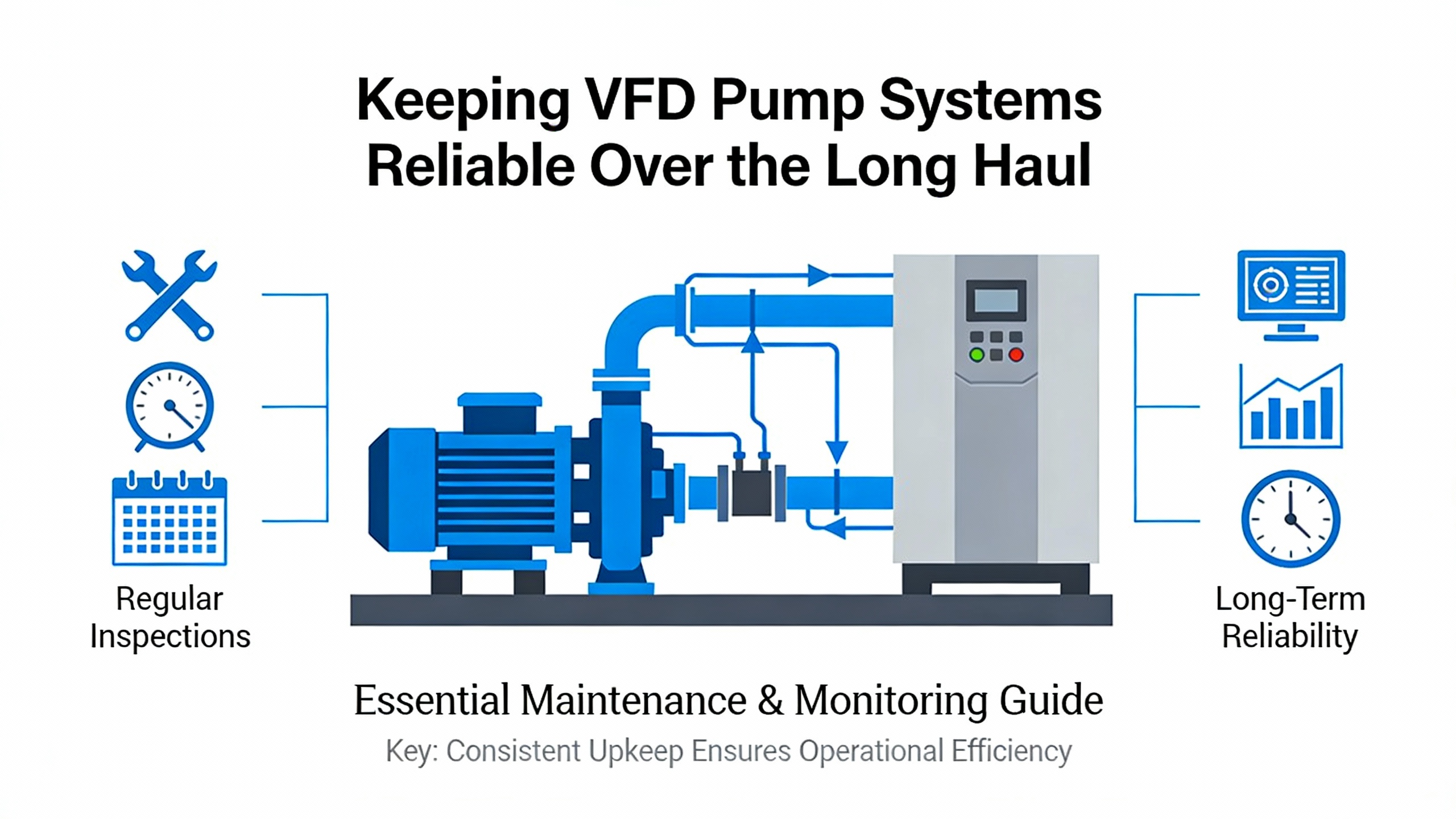
Pump & Dredge Source offers a realistic maintenance cadence for VFD pump units in harsh service. They suggest weekly visual inspections for dust, debris, overheating signs, unusual noise, and environmental issues; monthly cleaning of filters and vents plus checking enclosure integrity and moisture; and annual deep cleaning, connection tightening, diagnostics, and firmware updates. They also recommend proactive replacement of wear-prone components such as cooling fans every three to five years and DC bus capacitors roughly every seven years, subject to manufacturer guidance. Those time frames align with VFDS.orgŌĆÖs broader observation that many VFDs start to show age-related issues after five to ten years in tough environments unless preventive maintenance is in place.
Monitoring, maintenance intervals, and lifecycle planning
Most modern pump drives include significant self-diagnostic and monitoring capability. Veikong notes that many drives have built-in troubleshooting functions that flag issues such as irregular voltage, overtemperature, or blown fuses, typically with clear fault codes. Pump & Dredge Source emphasizes the value of continuous monitoring of parameters such as output voltage, current, temperature, and frequency to detect anomalies early and schedule maintenance or component replacement before failure.
Plant Engineering adds that some drives now estimate remaining life for key components like fans and capacitors and expose that data via maintenance monitors. When used properly, those estimates allow you to schedule component swaps during planned outages instead of during unplanned trips. VFDS.org encourages building a documented preventive maintenance program around these capabilities rather than relying purely on reactive repairs.
Longer term, VFDS.org also reminds owners that VFD technology and semiconductor devices evolve rapidly. During the twenty-year life of a large pump installation, multiple generations of drive hardware may come and go, and it is unrealistic to expect indefinite full support for any given model. They advocate treating VFDs as lifecycle-managed assets: engage the manufacturer or a trusted partner from design through commissioning, operate within environmental and loading guidelines, and plan for upgrades or replacements before obsolescence and parts scarcity become acute.
For critical pump systems where uptime is closely tied to safety or revenue, such as mine dewatering, refinery process units, or municipal sludge treatment highlighted by Pump & Dredge Source, this lifecycle view is essential. In those settings, a VFD failure is not a minor annoyance; it is a risk event. Align your maintenance strategy, spare parts inventory, and replacement planning with that reality.
Brief FAQ: Practical Decisions Around Pump VFDs
Do I still need a premium-efficiency motor if I am installing a VFD?
Consulting-Specifying Engineer compares the benefits of NEMA Premium motors with those of VFD speed control. Premium motors deliver low to mid single-digit efficiency gains at full load compared with older designs. VFDs on centrifugal pumps, by contrast, can deliver much larger savings by enabling speed turndown whenever full flow is not required. The correct answer is usually ŌĆ£both, if it is economical.ŌĆØ A premium-efficiency, inverter-duty motor paired with a properly applied VFD gives you solid efficiency at full load and the ability to save energy at partial load, while also withstanding the higher electrical stress associated with PWM voltage and fast switching.
Is it safe to buy the cheapest online VFD for a critical pump?
The Control.com discussion on positive displacement pump drives is blunt on this point. The author warns against buying very low-cost drives from unknown manufacturers, especially for applications where pump protection and uptime matter. Cheap drives may lack adequate overload capacity, robust protection functions, and reliable support. VFDS.org reinforces that the cost of downtime, emergency repairs, and process upsets often dwarfs the initial hardware savings from bargain drives. For critical pumps, treat the VFD as a long-term efficiency and reliability investment and favor established manufacturers with strong technical support and a track record in your industry.
How low can I safely run my pump speed?
There is no single universal minimum speed. Pumps.org and Consulting-Specifying Engineer both highlight several constraints. First, the pump itself must remain within a stable portion of its hydraulic curve; if speed is too low, you risk operating near shutoff, with poor efficiency and potential recirculation. Second, the motor must stay cool enough at reduced fan airflow; most TEFC motors have published minimum speeds or load-versus-speed curves for VFD duty. Third, you must avoid structural resonance bands identified by OEMs and standards such as ANSI/HI 9.6.8. In practice, you determine an allowable speed range with the pump and motor suppliers, encode that range as minimum and maximum frequency limits in the drive, and, where necessary, define skip frequency bands that the VFD will traverse quickly without dwelling.
Closing Perspective
When you look at a VFD pump through a power system lens, it is not just a black box making the motor turn slower. It is an ACŌĆōDCŌĆōAC converter sitting on your bus, reshaping current, interacting with your UPSs, transformers, and generators, and acting as the interface between your electrical infrastructure and your hydraulic process. If you choose the right drive for the pump type, engineer the environment and power quality properly, and maintain the system with the ŌĆ£clean, cool, dry, tightŌĆØ discipline advocated by multiple reliability studies, a pump VFD becomes one of the most effective tools you have for cutting energy use and improving uptime in modern plants.

References
- https://docs.nrel.gov/docs/fy17osti/68574.pdf
- https://www1.eere.energy.gov/manufacturing/tech_assistance/pdfs/variable_speed_pumping.pdf
- http://www.vfds.org/basic-variable-frequency-drive-maintenance-tips-603781.html
- https://www.pumps.org/pump-pros-know-variable-frequency-drives/
- https://www.nema.org/docs/default-source/motor-and-generator-guides-and-resources-library/2-variable-frequency-drives-benefits-v2.pdf?sfvrsn=eb8f0699_2
- https://electrical-engineering-portal.com/selecting-proper-variable-frequency-drive-vfd-motor-applications
- https://library.automationdirect.com/how-to-select-a-variable-frequency-drive/
- https://clefindustries.com/10-essential-maintenance-and-troubleshooting-tips-for-vfds/
- https://www.controleng.com/variable-frequency-drive-advice-best-practices-for-engineers/
- https://www.csemag.com/how-to-select-a-vfd/


 Videos
 News
News Applications


Leave Your Comment