Why Valve Actuators Matter So Much on Pipelines
In a modern pipeline, the ability to move a valve remotely and reliably is just as critical as the pipe steel itself. Valve actuators are the devices that take an input signal and convert it into mechanical motion to open, close, or modulate a valve. As described by Crane Engineering and First Flow Control, they provide the torque or thrust to move the disc, ball, or plug, hold it in position, and seat it tightly enough for reliable shutoff. In practice, that means the actuator determines whether a remote block valve actually closes when the control room hits the shutdown command.
Across oil and gas transmission, water and wastewater lines, and chemical or product pipelines, actuators enable remote operation, reduce manual intervention, and significantly cut human error. First Flow Control highlights how accurate, repeatable valve positioning supports better control of flow rates and pressure, which translates directly into more stable operation and higher product quality. Valveautomation-focused sources emphasize that automation also reduces labor and allows centralized oversight through SCADA and DCS systems.
From a reliability and power-supply perspective, actuators turn a simple mechanical valve into an electromechanical load that must be powered, protected, and monitored like any other critical asset. If you are responsible for industrial and commercial power systems, your remote valve stations are essentially small, distributed critical loads made up of actuators, PLCs, radios, and local power subsystems. When they fail, pipelines are exposed to uncontrolled flow, delayed isolation, and non-compliance with safety and environmental expectations.
A simple example illustrates the impact. Consider a remote, high-pressure block valve that might need to close a handful of times in a decade, but on those rare occasions it must close quickly and fully. Without an actuator, you are dispatching a crew with a truck, in any weather, hoping they reach the site in time and can physically operate the valve under full pressure. With a correctly selected and powered actuator, a single command from the control room executes the same function in seconds, with feedback confirming position and diagnostics captured for later review.
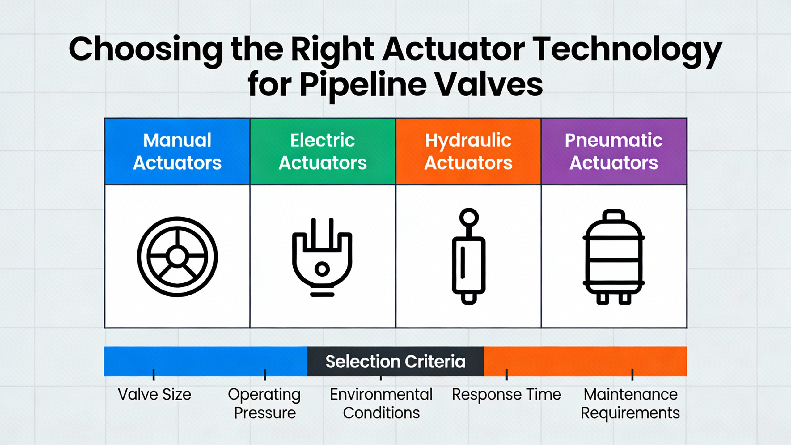
Choosing the Right Actuator Technology for Pipeline Valves
All valve actuators perform the same basic job, but they differ sharply in how they move and how they are powered. Elite Flow Control and Crane Engineering categorize actuators by motion and power source: linear vs rotary motion, and manual, pneumatic, hydraulic, electric, or electroŌĆæhydraulic power.
Most pipeline isolation valves are quarterŌĆæturn ball or butterfly designs, so rotary actuators are dominant. XintaiŌĆÖs guide to butterfly valves shows how a 90ŌĆædegree disc rotation is ideal for compact, highŌĆæcapacity pipeline service, and that translates directly into quarterŌĆæturn actuator requirements.
Actuator types through a pipeline lens
The main actuator families, with pipeline-relevant strengths and limits, can be summarized as follows.
| Actuator type | Key strengths for pipelines | Main limitations |
| Pneumatic | Fast response, high torque-to-weight, intrinsically non-sparking, tolerant of high duty cycles; preferred in explosive and high-pressure service per Elite Flow Control, Crane Engineering, and FSWelsford | Requires reliable, clean, dry air; leaks and poor air quality reduce performance; needs compressor or instrument air system |
| Hydraulic | Very high force and near continuous duty, well suited to large and high-pressure valves in harsh environments according to Elite Flow Control and FSWelsford | More complex systems with pumps, reservoirs, and hoses; risk of fluid leaks and contamination; higher maintenance burden |
| Electric | Precise positioning, easy PLC/SCADA integration, no need for local air or fluid systems, favored in building and water automation as noted by Elite Flow Control and First Flow Control | Limited duty cycle; vulnerable to power loss; special designs needed for hazardous areas; potential overheating at high cycling rates |
| ElectroŌĆæhydraulic | Combines electric control with hydraulic force, useful where high force and remote operation are needed, often offshore or in harsh locations per Elite Flow Control | Higher cost and complexity than single-technology options; more components to engineer, power, and maintain |
| Manual (lever, handwheel, gear) | Simple, low-cost, and reliable for infrequent or emergency-only local operation, highlighted by Elite Flow Control and Process Engineer | No remote control, slow response, unsuitable for frequent operation or hazardous locations where personnel access is limited |
In pipeline automation, manual actuators still have a role as backup or for rarely used local bypasses. However, automated block valves, remote-control valves (RCVs), automatic shutoff valves (ASVs), and rupture mitigation valves (RMVs) demand powered actuators, especially when they are part of safety instrumented functions.
A practical decision often comes down to what power is available and how the valve will be used. Crane Engineering notes that when plant air already exists, pneumatic actuators are often less expensive to operate than electric units, especially for small and medium valves. On long-distance pipelines with scattered sites, compressed air systems add their own complexity, so many operators favor electric or DC-powered actuators fed from battery-backed systems as described by Solarcraft.
Torque, speed, and duty cycle in high-pressure service
Correct sizing is where a reliability-focused engineer can add enormous value. FSWelsfordŌĆÖs guidance on actuated valves in high-pressure environments stresses that actuators must overcome packing friction, fluid inertia, and the full pressure differential under worstŌĆæcase conditions. Undersizing leads to slow or erratic stroking, inability to seal, and even surge events from valves slamming open or closed. Oversizing increases cost and can overstress valve stems and linkages.
Crane Engineering reinforces that actuator selection must start with valve type and torque requirements, then evaluate travel angle, operating speed, and the number of turns for multi-turn designs. Duty cycle is a key differentiator in high-cycle service. Pneumatic actuators can typically operate at a 100% duty cycle, while electric actuators are commonly limited to around 25% duty cycle. FSWelsford notes that modulation service can see hundreds or even thousands of starts per hour, where electric actuators may overheat and fail, whereas pneumatically driven units tolerate such cycling much better.
There is also a speed question. Fast-acting actuators are essential for emergency isolation and rupture mitigation. FSWelsford recommends fast action for frequent throttling and rapid isolation, but Process Engineer warns that very fast valve movement in highŌĆævelocity lines can drive water hammer and pipe vibration. In some mixing or surgeŌĆæsensitive applications, slower actuation through gear-reduced or carefully tuned actuators is actually safer.
Consider a highŌĆæpressure injection valve that must modulate frequently to control corrosion inhibitor flow. If it cycles roughly 900 times per hour, that is one stroke every 4 seconds. An electric actuator with a 25% duty cycle may spend more time cooling than moving in that regime, while a pneumatic rackŌĆæandŌĆæpinion actuator sized correctly for torque and supplied with clean, dry air can operate continuously without overheating. On the other hand, a large, rarely cycled mainline block valve may justify a highŌĆætorque electric or electroŌĆæhydraulic actuator, provided its starting current and failŌĆæsafe behavior are engineered correctly.
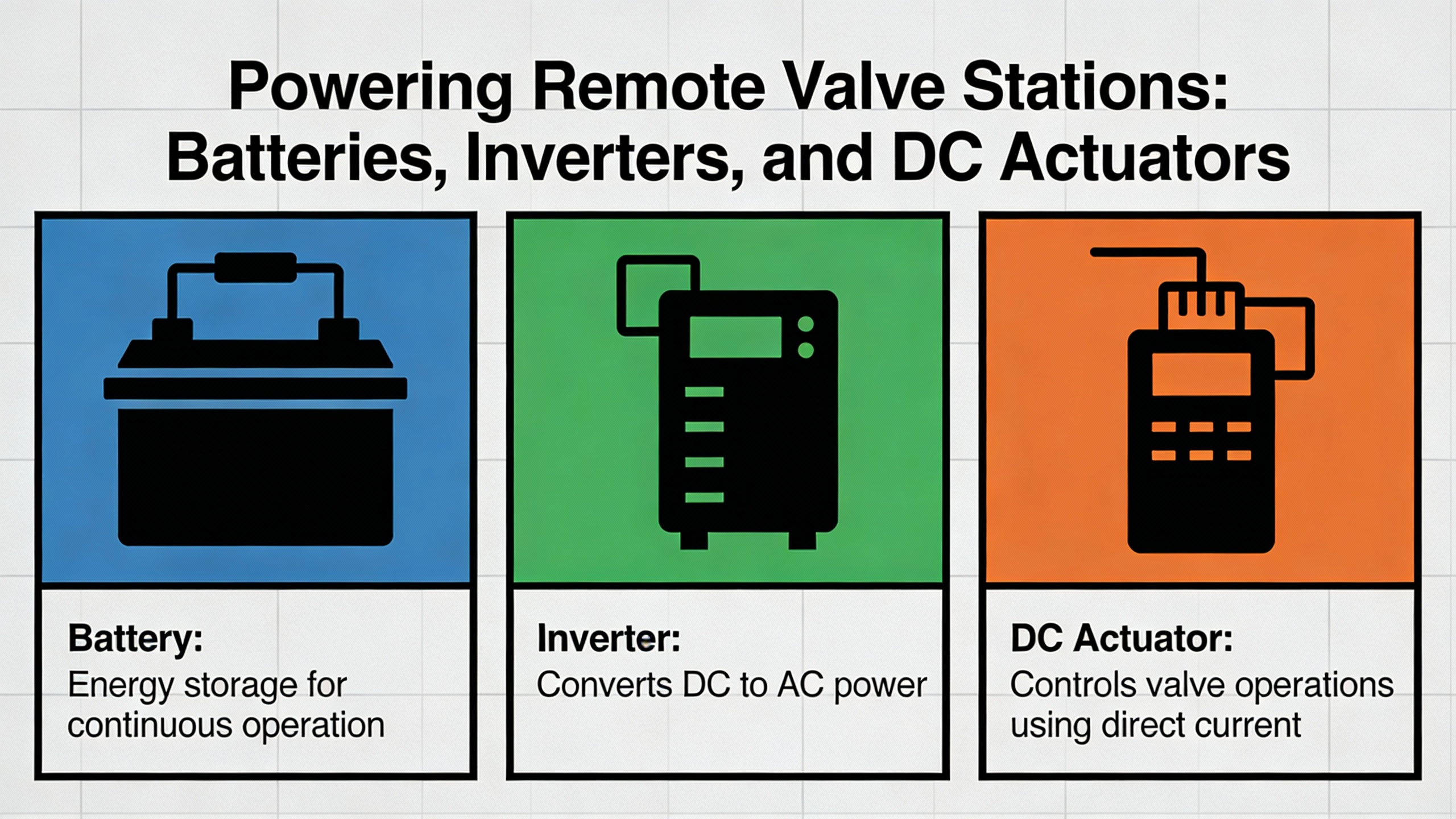
Powering Remote Valve Stations: Batteries, Inverters, and DC Actuators
From a power-system standpoint, each remote valve station is a small standalone critical load. SolarcraftŌĆÖs work on powering remote valve stations highlights typical configurations: a continuous 24 VDC load made up of a PLC, SCADA and communication equipment, plus occasional highŌĆæpower draws when actuators move.
Solarcraft recommends at least five days of battery autonomy so the station can ride through prolonged bad weather or other power interruptions while limiting daily discharge to about 20% of battery capacity. This approach extends battery life and keeps critical logic and communications powered until a technician can reach the site.
One of their examples considers a continuous 40 W load at 24 VDC. They show that supporting this load with conservative depthŌĆæofŌĆædischarge assumptions leads to roughly 200 Ah of nominal battery capacity, increased to about 313 Ah to account for endŌĆæofŌĆælife performance and other derating factors. Instead of thinking about energy in abstract terms, this framing makes it tangible: you are designing a longŌĆæduration DC UPS dedicated to each station, sized so that the PLC, radios, and sensors remain powered even if no charging occurs for several days.
Valve actuators add a very different load profile. Solarcraft notes that an actuator motor may range from less than 1 horsepower to tens of horsepower. The total energy per operation is surprisingly modest, but the instantaneous power can be enormous. In their example, a 10 hp actuator running a 2ŌĆæminute stroke consumes on the order of 250 Wh, which corresponds to about 14 Ah drawn from a 24 VDC battery bank when conversion losses are considered. While 14 Ah is small compared with a 300 Ah battery bank, the challenge lies in the starting current.
LockedŌĆærotor current (LRA) for induction motors is typically four to ten times the fullŌĆæload running current. Solarcraft reports that starting a 10 hp motor through an inverter can demand currents on the order of 1,000 A from a 48 V battery bank for a short period. To cope with that, their recommended practice is to size inverters so their maximum current capability is roughly six times the motorŌĆÖs running current and to choose inverters that can deliver double their rated output for about three seconds. As a rule of thumb, they suggest roughly 3 kW of inverter capacity per 1 hp of actuator motor, so an 8 hp motor would call for an inverter around 24 kW.
Viewed from a power protection perspective, this is the same design problem as feeding a large motor from a UPS: steady-state loads are small, but inrush is massive and must not collapse the DC bus or trip protective devices. Cheap, offŌĆætheŌĆæshelf inverters are not designed for repeated high inrush events, especially in harsh outdoor environments, which is why Solarcraft explicitly cautions against using lowŌĆæcost commercial inverters for critical safety valve systems.
For small and medium actuators, one very effective strategy is to bypass the inverter altogether. Solarcraft notes that 24 and 48 VDCŌĆæpowered actuators are available from several manufacturers and recommends them for smaller actuators. These actuators draw their starting current directly from the battery bank, eliminating conversion losses and simplifying the system. Direct DC operation reduces component count, improves fault tolerance, and can significantly cut cost, because the battery bank is already there to support continuous 24 VDC logic loads.
A simple sizing exercise shows how these recommendations play out. Suppose a remote valve station has the same continuous 40 W logic load and one DC actuator whose occasional operation adds roughly 250 Wh per day during testing or rare events. Over a fiveŌĆæday autonomy period, the continuous load consumes about 200 Wh per day, or roughly 1,000 Wh total, while even daily actuator testing would add another 1,250 Wh. A 24 V battery bank sized around the 313 Ah that Solarcraft describes provides about 7,500 Wh of nominal energy, more than enough margin when daily depth of discharge is kept below approximately 20%. In other words, the actuator energy is not what drives battery sizing; it is starting current and autonomy that dominate, guiding you toward robust DC buses and appropriately overrated inverters or DC actuators.
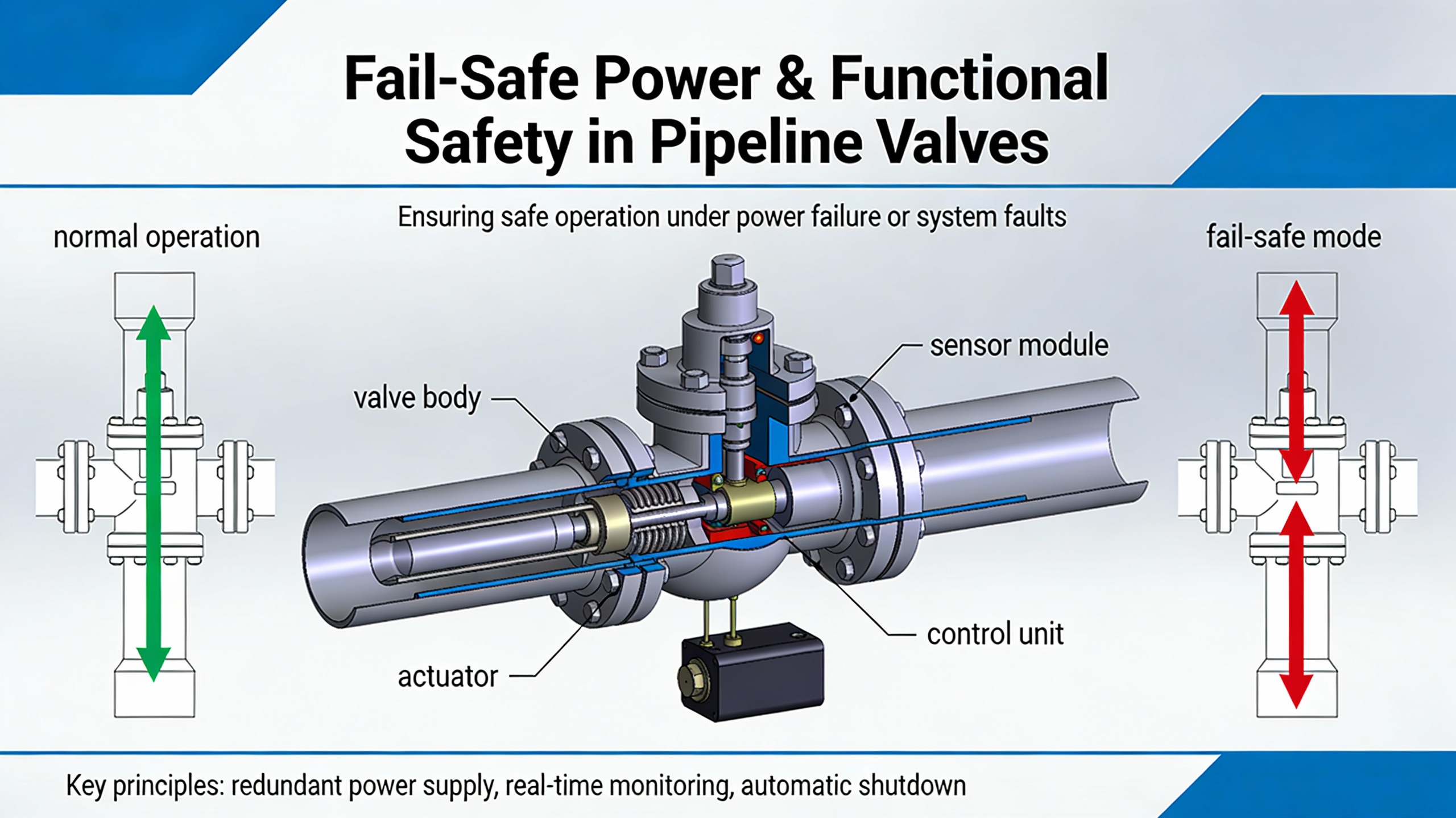
Fail-Safe Power and Functional Safety for Pipeline Valves
Many pipeline actuators are part of safety instrumented systems rather than purely operational control. ISA explains that a safety instrumented system typically consists of a sensor, a safety PLC, and an actor, which in valve applications means the actuator plus the valve. The system is designed to bring the plant to a safe state during emergencies, and its performance is expressed in terms of safety integrity levels under IEC 61508 and IEC 61511.
A common misunderstanding is that selecting SILŌĆærated components automatically delivers a safety function of the same SIL. ISA emphasizes that using SIL 2ŌĆæcapable components does not guarantee a SIL 2 safety function. Designers must evaluate probability of failure on demand (PFD) and ensure that each componentŌĆÖs PFD contribution fits within the total budget for the safety instrumented function. As a rule of thumb highlighted in the ISA guidance, an actuatorŌĆÖs PFD contribution should be kept to about a quarter of the allowed PFD for the target SIL. If the actuator alone consumes most of the permitted PFD, the overall safety function will not achieve the required risk reduction, regardless of how good the sensor and logic solver are.
From a power-system angle, failŌĆæsafe actuation and PFD are tightly linked. Crane Engineering and FSWelsford describe common failŌĆæsafe mechanisms: pneumatic and hydraulic actuators often use springŌĆæreturn designs or accumulators to drive the valve to a defined safe position when power or control signals are lost. Electric actuators cannot easily store mechanical energy in large springs, so they rely on battery backup or supercapacitor systems to power a closing stroke, or they surrender failŌĆæsafe performance.
SolarcraftŌĆÖs focus on RMVs, ASVs, and RCVs underscores that many remote valve stations relate directly to rupture mitigation and automatic isolation. Their recommendation for at least five days of battery autonomy is partly about enabling technicians to reach a site, but it also ensures that safety functions remain available through extended power disturbances, rather than becoming dormant once a storm passes and grid power is out.
A realistic design discussion therefore needs to connect actuator selection, failŌĆæsafe mechanism, and power architecture. A springŌĆæreturn pneumatic actuator supplied from a highŌĆæreliability instrument air system with appropriate freeze protection naturally moves to its safe position when air is vented. For an electric actuator, failŌĆæsafe may involve a local DC energy store sized for at least one full stroke at endŌĆæofŌĆælife conditions, plus monitoring to detect and alarm on any degradation in that energy store. ISA further recommends comprehensive safety documentation from actuator manufacturers, including safety figures, test reports, and proof-test procedures, so that designers can correctly account for actuator behavior in the overall safety integrity calculations.
Imagine a safety function that must close an upstream block valve on a highŌĆæpressure pipeline segment during a leak detection event. If the target safety integrity level allows a certain maximum PFD, and the actuator accounts for roughly a quarter of that allowance, then PFD contributions from the sensor and logic solver must share the remainder. If a design choice such as a marginal inverter or undersized battery bank increases the chance that the actuator will fail to move on demand, the actuatorŌĆÖs PFD contribution effectively increases, potentially pushing the safety function out of its required SIL. From a reliability advisorŌĆÖs perspective, this is a direct argument for robust power subsystems and conservative margins on actuator power and failŌĆæsafe mechanisms.
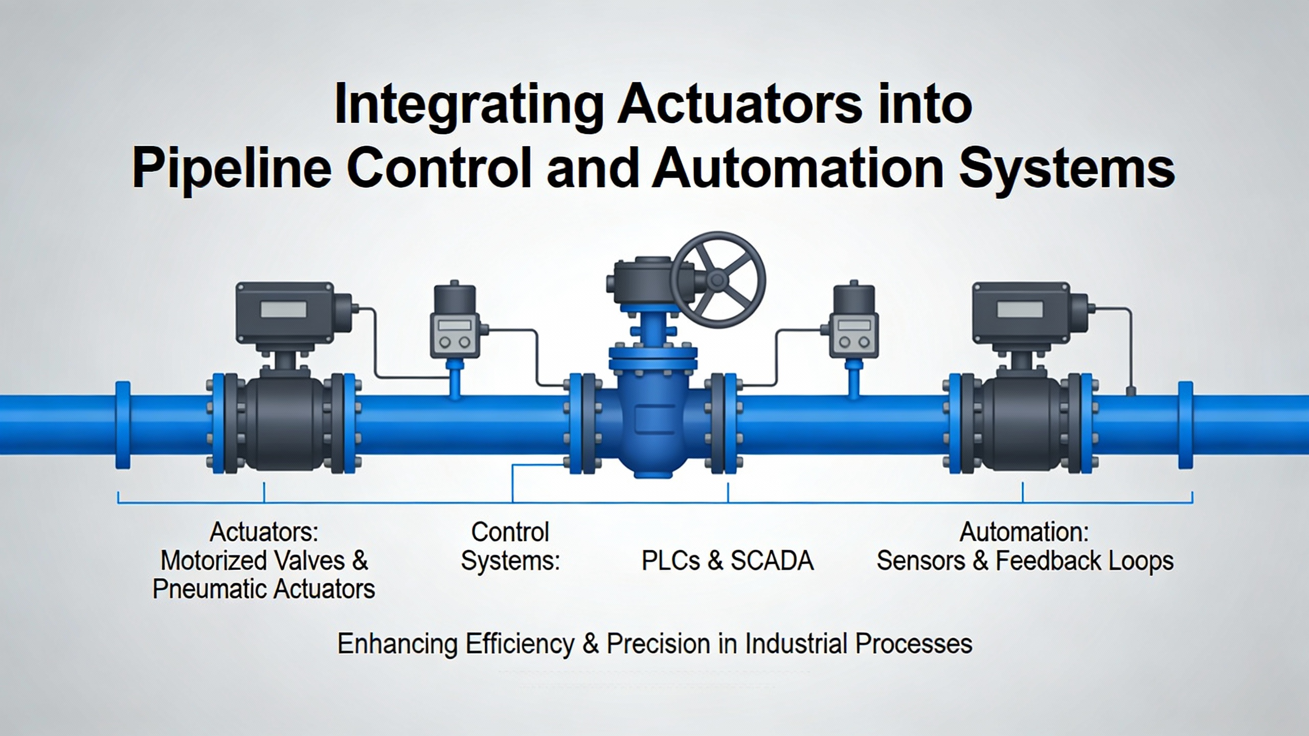
Integrating Actuators into Pipeline Control and Automation Systems
Mechanically mounting an actuator to a valve is straightforward; integrating it into a modern automation and control architecture is not. ISA notes that while the mechanical interfaces between valves and actuators are standardized, the communication interfaces to DCS and SCADA systems evolve continuously. Host system integration and functional safety are now dominant issues in valve actuation, especially in complex process plants and extensive pipeline networks.
Fieldbus and digital communication technologies such as Profibus DP, Modbus RTU, Modbus TCP/IP, FOUNDATION Fieldbus, and HART extend actuator capabilities far beyond simple open/close commands. ISA explains that these protocols allow transmission of device parameters, diagnostics, and operating data, enabling remote parameterization, commissioning support, and centralized maintenance and asset management. Valve automation system guides emphasize similar themes: automated valves equipped with sensors, limit switches, positioners, and digital links become rich data sources that support predictive maintenance and optimization.
The benefits are compelling, but they require careful engineering. ISA emphasizes that protocol conformity should be verified by independent organizations and that DCS manufacturers often perform their own integration tests with representative devices. Redundancy strategies need to be defined early, covering communications paths, network devices, and actuators, with data interfaces narrowed to applicationŌĆærelevant signals to keep bandwidth reasonable and cycle times short.
WestlockŌĆÖs perspective on valve control systems adds another layer: accurate calibration and maintenance of sensors and positioners are critical to efficiency. Faulty or drifting sensors, sticky valves, and poor timing all lead to higher energy use, more material waste, and increased downtime. Integrating actuators into a control system is therefore not only about fieldbus wiring and addressing, but about measurement quality and loop tuning as well.
Consider bringing a new remote valve station online. A robust approach might include a fieldbus-connected actuator with builtŌĆæin diagnostics, limit switches feeding back exact open/closed position, and a positioner capable of modulating for throttling service. Integration with SCADA would then include not just the command word and position feedback, but device health indicators, partial-stroke test results for safety valves, and alarms for abnormal torque or temperature. Westlock and valve automation guides suggest that this kind of data-rich integration supports real-time visibility and faster response to anomalies, whereas a simple on/off interface forces operators to rely on indirect signs of trouble.
Reliability, Maintenance, and Compliance for Actuated Pipeline Valves
Actuator valves are only as reliable as the maintenance and monitoring strategies around them. Best Flow and First Flow Control both highlight that regular maintenance reduces unplanned shutdowns and repair costs, with one San Francisco facility reporting roughly a 33% reduction in repair expenses after implementing regular monthly inspections. They point out common failure causes such as excessive cycling, harsh environments with dust and moisture, improper actuatorŌĆætoŌĆæsystem matching, and overheating from running actuators beyond their duty class.
Early warning signs include unusual sounds, dripping or leaks, sluggish or erratic motion, and position feedback that does not match commanded positions. Westlock adds that valve stiction from corrosion or poor lubrication, as well as leakage when valves are closed, undermines both safety and efficiency. Where manual inspection is impractical, as on remote pipelines, predictive monitoring and remote diagnostics become essential. Valve actuation and control articles describe how trends in actuator torque, stroke time, and positioner output can be used to detect emerging issues before they become catastrophic failures.
Typical maintenance practices recommended by Best Flow, First Flow Control, and Westlock include regular cleaning of actuators and surrounding areas, lubrication of moving parts where the manufacturer specifies it, inspection and replacement of seals and gaskets, verification of electrical connections, and periodic calibration of sensors and positioners. First Flow Control suggests keeping a maintenance log and scheduling routine inspections, often at intervals of about six months, with adjustments based on environmental severity and manufacturer guidance.
Plant EngineeringŌĆÖs work on process valve safety reinforces that storage, handling, and installation practices also affect reliability. Valves should be stored clean and dry, installed according to orientation and support requirements, and torqued correctly to prevent misalignment and fugitive emissions. Heavy actuated valves must be lifted using proper lifting points, and actuators must be protected from damage during handling. Poor practices at this early stage can lead to premature failures that no amount of downstream maintenance can fully correct.
Best Flow also reminds operators of regulatory dimensions. In the United States, actuator valves and their power systems operate under occupational safety requirements such as OSHA standards for hazardous locations and environmental rules such as EPA regulations on fugitive emissions. Accurate documentation, awareness of regulatory changes, and periodic audits help ensure that pipeline valve automation not only operates reliably, but also complies with safety and environmental expectations.
A practical way to visualize the payoff is to scale the San Francisco example. If a pipeline operator currently spends $300,000 per year on actuator-related repairs and unplanned valve work, a similar oneŌĆæthird reduction through structured inspection and predictive monitoring would save on the order of $100,000 annually. That kind of savings can easily justify investments in better diagnostics, robust DC power systems with appropriate inverters or DC actuators, and staff training on installation and maintenance best practices.
Putting It All Together: A Pipeline Station Example
To see how these threads come together, consider a remote mainline block valve station on a highŌĆæpressure oil or gas pipeline. The station has one large quarterŌĆæturn ball valve, continuous control and communication loads at 24 VDC, and must close automatically as part of a rupture mitigation system.
From an actuation standpoint, guidance from Elite Flow Control, FSWelsford, and Xintai would push you toward a highŌĆætorque rotary actuator. If the valve is very large or pressure is extreme, hydraulic or electroŌĆæhydraulic actuation may be justified to obtain the necessary torque and frequent testing capability. If the power and environmental conditions allow, a springŌĆæreturn pneumatic actuator fed from a wellŌĆædesigned instrument air system would offer very clear failŌĆæsafe behavior. In situations where air is not practical, a DCŌĆæpowered electric actuator becomes more attractive.
On the power side, following SolarcraftŌĆÖs recommendations, you would size a battery bank for at least five days of autonomy at the continuous 24 VDC load, ensuring that daily depth of discharge stays near 20% and that PLC, leak-detection logic, and communications remain alive through prolonged outages. For an AC motor-driven actuator, you would select an industrial inverter with a continuous rating and overload capability that align with the approximate 3 kW per horsepower rule, checking that maximum current is about six times the motorŌĆÖs running current and that it can handle starting currents in the four-to-ten-times full-load range without collapsing. For a smaller actuator, you might bypass the inverter entirely and choose a 24 or 48 VDC actuator drawing directly from the battery bank to reduce complexity and loss points.
In terms of safety and integration, ISAŌĆÖs guidance suggests treating the actuator and valve as part of a safety instrumented system with a defined SIL requirement. The actuatorŌĆÖs PFD contribution would be engineered to remain around a quarter of the allowed PFD for the safety function, with documentation from the actuator vendor supporting the calculations. The actuator would be tied into SCADA using fieldbus or suitable digital protocols, enabling remote diagnostics, partial-stroke tests, and status verification. Westlock and valve automation sources would encourage you to incorporate accurate position feedback, robust calibration procedures, and periodic functional testing.
Finally, Best Flow, First Flow Control, and Plant Engineering would guide your maintenance strategy and training. Technicians would follow standardized procedures for handling, installing, and periodically exercising the valve and actuator; maintenance teams would track torques, stroke times, and diagnostic indicators in an asset management system; and safety teams would ensure that lockout/tagout, hazard awareness, and environmental compliance are embedded in daily practice. The result is a remote valve station that behaves as a well-engineered, self-contained critical power and control node: resilient to power disturbances, responsive to remote commands, and predictable when the safety system demands action.
FAQ: Common Decisions About Pipeline Valve Actuators
How do I choose between electric and pneumatic actuators for a remote pipeline valve?
Crane Engineering, Elite Flow Control, and FSWelsford all highlight power availability, duty cycle, and environment as dominant factors. If you already have a reliable, dry instrument air system and the valve will see frequent cycling or high duty, a pneumatic actuator offers excellent durability, fast response, and natural compatibility with failŌĆæsafe springŌĆæreturn designs. In remote stations where providing compressed air is difficult, batteryŌĆæbacked electric or DC actuators integrated into a 24 or 48 VDC power system, as described by Solarcraft, are often more practical. In that scenario, it is important to respect duty cycle limits on electric actuators and ensure that inrush currents and failŌĆæsafe power are fully covered by the inverter and battery bank design.
How much battery do I really need at a remote valve station?
Solarcraft recommends sizing batteries for at least five days of autonomy at the continuous DC load, with daily discharge around 20% of capacity. Their example of a 40 W continuous load at 24 VDC leads to roughly 200 Ah of nominal capacity, increased to about 313 Ah after derating. Actuator strokes add relatively little energy consumption compared with this base load, but they significantly influence inverter selection and starting current requirements. In practice, this means that battery sizing for remote valve stations is usually driven by logic and communications uptime, while inverter and actuator choices are driven by shortŌĆæduration, highŌĆæcurrent demands.
Can I rely on low-cost commercial inverters for actuators in safety-critical pipeline service?
Solarcraft explicitly cautions against this. Actuator motors, particularly in the several-horsepower range, draw very high lockedŌĆærotor currents that can reach many times the full-load current. Low-cost commercial inverters are generally not designed to handle the repeated, highŌĆæinrush events and harsh outdoor conditions typical of pipeline environments. For RMVs, ASVs, and RCVs that protect people and the environment, using industrial-grade inverters with the overload capability and protective features recommended by Solarcraft, coupled with properly sized battery banks, is a far more robust and defensible choice.
In pipeline automation, a valve actuator is never just a motor on a valve. It is a power-dependent safety device sitting miles away from your nearest substation. Treating actuator selection, power architecture, and integration with the same rigor you apply to critical UPS and inverter systems is what turns remote valves into reliable, responsive guardians of pipeline flow.
References
- https://www.academia.edu/45131578/Pipeline_Valves
- https://faculty.wcas.northwestern.edu/ipsavage/805.pdf
- https://reclaim.cdh.ucla.edu/index.jsp/textbook-solutions/A25I5d/Emerson%20Control%20Valve%20Handbook.pdf
- https://dspace.mit.edu/bitstream/handle/1721.1/100118/929642930-MIT.pdf?sequence=1&isAllowed=y
- https://aglaw.psu.edu/wp-content/uploads/2020/06/finalvalvestudy.pdf
- https://blog.isa.org/integrate-valve-actuators-automation-system
- https://blog.craneengineering.net/quick-and-dirty-guide-to-valve-actuators
- https://www.solarcraft.net/resources/articles/powering-remote-valve-stations-best-practices
- https://svf.net/application/files/5017/0895/9789/SVF_eBook_A_Comprehensive_Guide_to_Valves__Actuators_and_Controls.pdf
- https://www.bestflowvalve.com/guide-to-choosing-the-right-actuator-valve.html


 Videos
 News
News Applications


Leave Your Comment