Designing industrial automation around UPS systems, inverters, and power protection equipment is not just about keeping motors spinning when the lights flicker. It is about building a control system architecture that stays predictable under stress, recovers gracefully after faults, and can be expanded without tearing out what you installed last year. As a power system specialist and reliability advisor, I have seen plants run flawlessly through utility disturbances because their automation and power protection were architected together. I have also seen facilities where a poorly conceived control scheme turned a minor power blip into a prolonged outage.
This guide focuses on that first outcome. Drawing on established guidance from organizations and practitioners such as Grace Automation, DECOWELL, ISA, PanelBuilderUS, Cisco, Emerson, Qt, Red Hat, and academic work on modular industrial control, we will walk through how to plan control system architecture for industrial automation in powerŌĆæsensitive environments.
The decisions that matter most fall into a few recurring questions. What are you really trying to protect, and how critical is continuous power to each part of your operation? How do you structure control, network, and data layers so that UPS and protection functions remain dependable even when higherŌĆælevel systems or networks fail? How do you integrate SCADA, MES, IIoT analytics, and modern HMIs without overcomplicating or undermining the core protection logic? The sections that follow treat these questions one by one, with concrete examples grounded in real industrial practice.
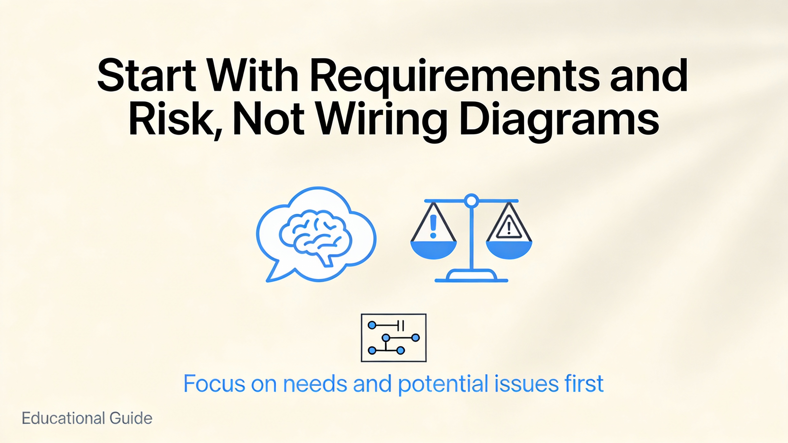
Start With Requirements and Risk, Not Wiring Diagrams
Grace Automation emphasizes that successful control projects begin with clearly defined requirements, including objectives, functional needs, performance targets, and constraints rather than with a hardware catalog. That advice is even more important when industrial and commercial power supply systems are involved, because a vague requirement like ŌĆ£keep the line running during an outageŌĆØ is not enough to design a resilient architecture.
You should first separate loads into categories such as safetyŌĆæcritical, productŌĆæcritical, and convenience. SafetyŌĆæcritical loads include emergency lighting, fire pumps, and ventilation for hazardous areas. ProductŌĆæcritical loads include process control panels, instrumentation, and production equipment where a sudden power loss would scrap highŌĆævalue material or cause long restart times. Convenience loads cover office lighting or nonessential comfort systems. Even if you do not assign exact dollar values, making these distinctions shapes everything from how much UPS capacity you install to where you place control functions in the architecture.
At the same time, PanelBuilderUS stresses that safety must come before productivity, even for simple control tasks such as starting and stopping a pump. That perspective brings standards into the architectural conversation early. Electrical and control equipment must comply with NFPA fire codes, NEMA electrical standards, OSHA regulations, and UL 508A requirements for industrial control panels. OSHA lockout and tagout rules in particular influence how you design the system so that all forms of hazardous energyŌĆöelectrical, pneumatic, hydraulic, or mechanicalŌĆöcan be positively isolated during maintenance. In a powerŌĆæheavy plant, that means thinking about the coordination between UPS output breakers, bypass paths, and downstream disconnects at the same time you are sketching PLC racks and network switches.
A programmable logic controller, as described in research summarized by industrial automation literature, is essentially a rugged realŌĆætime computer that reads field inputs, executes deterministic control logic, and drives outputs. When you combine PLCs with HMIs and SCADA systems, you create the nervous system that will orchestrate inverters, static transfer switches, and protective relays during disturbances. Grace Automation and related sources highlight that this logic must not only meet process requirements, it must remain easy to maintain and modify as production needs evolve. For a UPSŌĆæbacked plant, that implies designing control strategies and automation sequences that can accommodate future power system changes such as additional UPS modules, new feeders, or expanded critical loads without wholesale rewrites.
A practical example makes this concrete. Imagine a facility where a single PLC controls both a production line and the automatic transfer between utility power and a UPSŌĆæbacked bus. If all logic is intermixed, adding a new machine to the line can inadvertently affect transfer behavior, especially if naming and modularization are weak. By defining up front that power transfer logic is a separate, safetyŌĆærelated module with strictly controlled interfaces, you reduce the risk that later optimization of sequence timing will destabilize the most critical function: keeping your loads energized safely.
Think in Layers: Applying the Purdue Model to PowerŌĆæSensitive Control
The Purdue hierarchy, as explained by ISA and the broader Purdue Enterprise Reference Architecture work, is a functional, not physical, model that has guided industrial control design for decades. It organizes functions from sensors and actuators at the bottom up through realŌĆætime control, supervisory control, plant operations management, and business systems. The key insight is that different layers operate on different time scales and scopes of responsibility and must be able to tolerate failures at other layers.
The Purdue guidance, reinforced by ISAŌĆæ95 and ISA/IEC 62443 security standards, recommends that lower levels remain capable of safe operation even if higher levels are unavailable. That leads to an orderŌĆæofŌĆæpriority mindset. Field devices should operate or fail safely without depending on controllers. Controllers should be able to run without supervisory systems. Supervisory control should continue without plant historians. And plant operations should not depend on enterprise resource planning systems or cloud services being online.
In a powerŌĆæfocused plant, this hierarchy becomes a design tool rather than a theoretical diagram. UPS controllers, inverter control boards, and protective relays correspond to the lowest levels, with PLCs and local SCADA handling coordination above them. Data historians, MES systems, and cloudŌĆæbased analytics sit higher still. The architecture should be arranged so that any layer above the realŌĆætime control of power devices is a convenience, not a requirement, for safe and continuous operation.
The table below illustrates typical roles of each functional level when viewed through the lens of critical power control.
| Functional Level (Purdue) | Typical Role in PowerŌĆæSensitive Automation |
| Level 0 (field) | Sensors, contactors, breakers, UPS and inverter control boards, relay trip coils, temperature and current sensors |
| Level 1 (basic control) | PLC logic for switchgear, generator start sequences, breaker interlocking, static transfer coordination |
| Level 2 (supervisory) | Local SCADA, operator HMIs, dashboards for UPS status, alarm management, manual control stations |
| Level 3 (operations) | Plant historians for power events, energy management applications, maintenance planning tools |
| Level 4 (enterprise) | Business systems, reporting, cloud analytics, fleetŌĆæwide optimization of maintenance and energy use |
ISAŌĆÖs discussion of resilience makes a crucial point: if a cloud analytics platform fails, a plant historian fails, or siteŌĆætoŌĆæSCADA communications are interrupted, your control design should ensure that the lower levels continue to operate safely and that required regulatory data can be captured locally for later recovery. For power systems, that can mean logging transfer events and trip causes directly at the controller level rather than relying solely on a central historian.
Consider an example of a utility failure leading to UPS operation and then generator start. At the lowest level, UPS control boards keep the DC bus and output within limits, transfer to battery, and regulate inverter output. Level 1 PLC logic coordinates fast breaker actions, such as opening utility feeders and closing alternate sources. Level 2 SCADA informs operators and provides manual override screens but is not needed to complete the sequence. At Level 3, historians record the sequence for rootŌĆæcause analysis. Level 4 may send alerts to corporate teams or trigger work orders. If a cyber incident or wideŌĆæarea network failure knocks out Levels 3 and 4, and even Level 2 graphics for a time, the plant should still ride through the event safely because Levels 0 and 1 have everything they need.
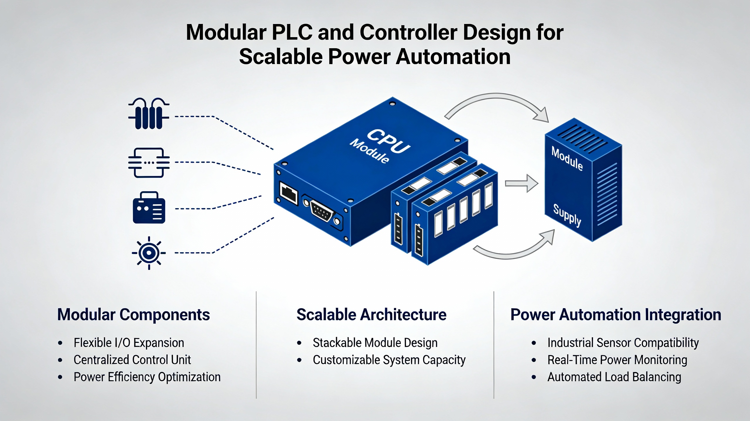
Modular PLC and Controller Design for Scalable Power Automation
DECOWELLŌĆÖs guidance on PLC programming for scalable automation emphasizes modular architectures in both hardware and software. Instead of a single monolithic program controlling everything from conveyor belts to switchgear, the recommendation is to partition the system into discrete functional blocks such as I/O modules, motion control, communication interfaces, and separate motor or subsystem modules. Each module has wellŌĆædefined interfaces and responsibilities.
For powerŌĆæoriented systems, that translates into separate logical modules for feeder protection, bus transfer, generator control, battery management, and load shedding. These modules may share common services such as time synchronization and alarm handling, but their internal logic remains encapsulated. DECOWELL notes that modularity brings clear benefits: easier expansion, because additional modules can be plugged into a PLC rack or software project without redesigning the core; maintainability, because faults can be localized and modules replaced or updated individually; and reuse, because a standard ŌĆ£breaker control moduleŌĆØ can be applied across multiple panels or even sites.
Programming language choice also affects modularity and maintainability. IEC 61131ŌĆæ3 defines languages including Ladder Diagram, Structured Text, and Function Block Diagram. DECOWELL points out that Ladder Diagram is well suited for discrete logic and relayŌĆæreplacement tasks and is often preferred by maintenance technicians. Structured Text excels at complex algorithms and data handling, such as loadŌĆæshedding priority calculations or battery stateŌĆæofŌĆæcharge estimation. Function Block Diagram is effective for modular function blocks that can be reused, such as standard motor starters or breaker interlock logic. A practical approach is to use Ladder for straightforward interlocking, Structured Text for calculations and data processing, and Function Block Diagram for reusable control blocks, while keeping the program organized into layers of hardware abstraction, process logic, and safety or override functions.
Academic work on reconfigurable CNC architectures adds another perspective that is useful even outside machine tools. Researchers describe how discrete behavior, such as state changes and error handling, is well captured by finite state machines, while continuous behaviors, such as interpolation or velocity planning, are better modeled through dependency networks that express module dependencies and execution priorities. When you apply that thinking to power control, breaker and transfer states can be modeled as state machines with clearly defined transitions, while continuous analog behavior such as load sharing between parallel inverters or ramped voltage regulation can be treated as continuous control layers. The combined model reduces complexity compared with trying to force everything into a single style of logic.
Modularity has tradeoffs. It demands strict naming conventions and interface discipline, otherwise a ŌĆ£modularŌĆØ project devolves into an unstructured collection of blocks. DECOWELL recommends descriptive tag names, using prefixes for data types and structured formats that encode zone, line, device, and function in the tag name. Consistent naming, backed by a shared guideline document, becomes more important as total tag counts rise into the tens of thousands. The payoff is during commissioning and future troubleshooting, when engineering and maintenance teams can quickly understand what a signal represents and which module it belongs to.
An example brings this to life. Suppose you are designing control for a plant with three UPS systems feeding different switchgear lineups, each with its own static transfer switches and downstream critical loads. A modular design would create a standard UPS module that encapsulates status handling, alarm processing, and interface to the UPS vendorŌĆÖs protocol, then apply that module three times with different parameter sets. A similar pattern would exist for static transfer switches. The lineups might share a common loadŌĆæshedding module that receives normalized priorities from each feeder. If a fourth UPS is added a year later, you can instantiate the existing modules rather than rearchitecting the entire project.
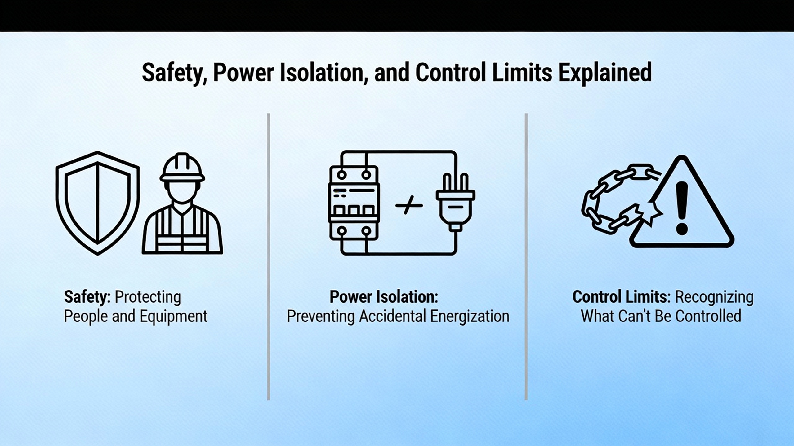
Safety, Power Isolation, and the Limits of What Control Can Fix
PanelBuilderUS is blunt on one point: nonŌĆæexperts should not design or install industrial control systems without proper guidance, and all such systems must be designed with safety as the top priority. That principle is easy to agree with and surprisingly easy to compromise when project schedules are tight and power protection schemes get complicated.
From a safety standpoint, PanelBuilderUS highlights several design practices that are particularly relevant in power rooms. There must be clearly labeled emergency stop functions that remove system power in a controlled manner, using external electromechanical interlocks independent of PLC or solidŌĆæstate outputs. Control systems must implement orderly shutdown sequences that move actuators, including breakers and motorized disconnects, into failŌĆæsafe positions when faults occur. Proper grounding is essential both to prevent shock and to reduce electrical noise, and overcurrent protection must be coordinated so that a fault on one circuit does not unnecessarily trip upstream devices and take down wider sections of the plant.
Furthermore, any closedŌĆæloop control system, such as an automatic power factor correction bank or a voltage regulation loop, must be designed to shut down safely if the feedback signal is lost. Allowing a controller to continue driving outputs based on stale or invalid measurements can lead to dangerous operating conditions. For example, if current transformers feeding a protective relay fail or become disconnected, the relay should not assume zero current and block trip signalsŌĆöit should detect the faulted measurement condition and place the system into a safe, known state.
The pitfalls of expecting control logic to fix underlying mechanical or process design flaws are illustrated vividly by a case study from Control Engineering. In that example, a pharmaceutical pilot plant used temperature control units and a liquid nitrogen heat exchanger to reach very low process temperatures, with the liquid nitrogen cooling capability reaching approximately minus 108┬░F. The way valves and piping were arranged caused the control valve to act as a bypass under certain setpoints. That routing starved the heat exchanger, led to low flow, and ultimately caused the remaining fluid to freeze, destroying temperature control. Because mechanical changes were off the table, integrators attempted to solve the issue purely through automation by tweaking setpoint offsets between the temperature control unit and the liquid nitrogen loop. Fixed offsets worked only at certain operating points. Linear models helped in others but caused freezing in midŌĆærange conditions. Eventually, a more complex quadratic offset model delivered acceptable performance across the full range, but only after weeks of testing and high consumable costs.
This case underscores a lesson that applies directly to power systems. You cannot compensate for poor physical designŌĆöwhether misŌĆærouted cables, misŌĆæsized breakers, or badly coordinated protectionŌĆöpurely through clever PLC programming. Control strategies can mitigate issues and optimize performance, but they cannot repeal physics. When you plan a control architecture for an automated power system, engage electrical and process engineers early enough that bus configurations, breaker layouts, and protective schemes are fundamentally sound. Otherwise, you risk building layers of complexity into your control logic just to keep a flawed system barely within its safe operating envelope.
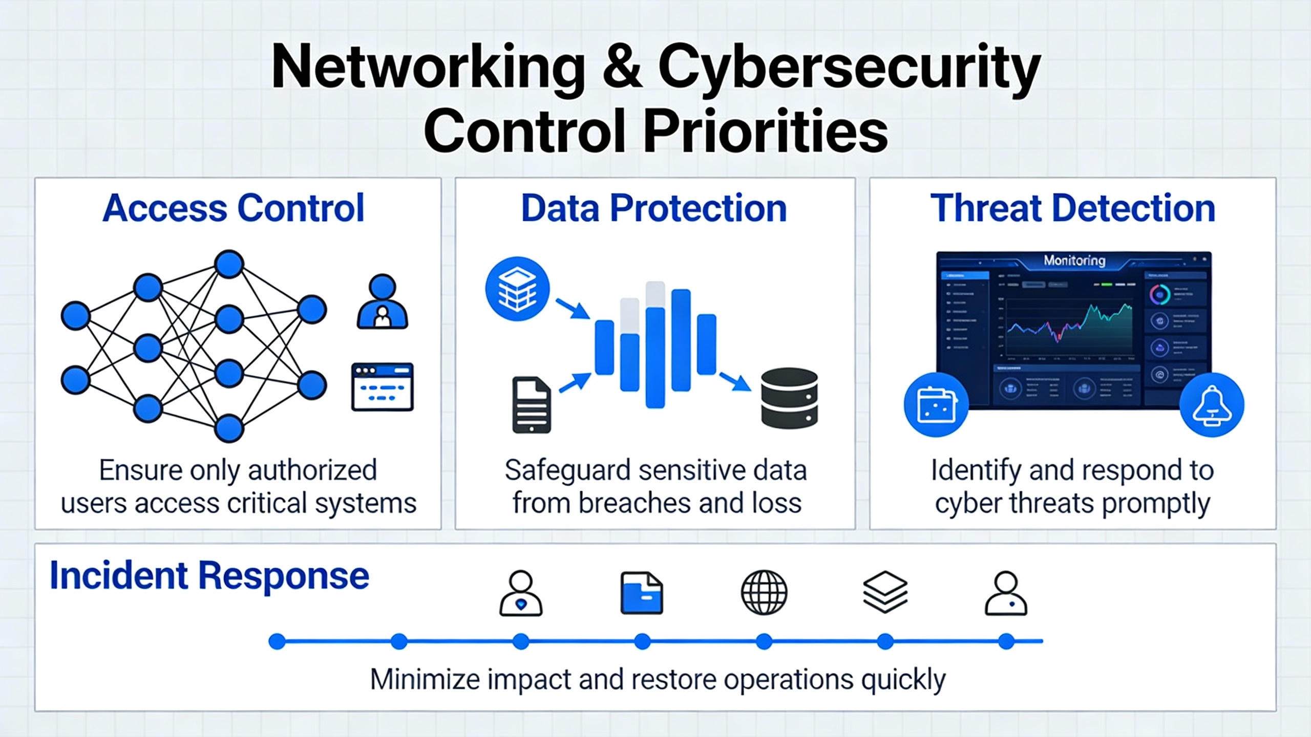
Networking and Cybersecurity Around Control Priorities
Modern automation systems no longer live on isolated islands. DECOWELL notes that PLCs now integrate with HMIs, SCADA, manufacturing execution systems, edge gateways, and cloud platforms, with communication networks and protocols forming the backbone. CiscoŌĆÖs industryŌĆævalidated design work focuses specifically on secure and reliable network foundations for digitizing industrial operations. The shared message is clear: network design and cybersecurity are part of control system architecture, not addŌĆæons.
ISAŌĆÖs treatment of the Purdue model reminds us that levels are functional rather than strictly physical, but security practice, particularly ISA/IEC 62443, encourages designers to define security zones and conduits that align with those functional layers. In practical terms, that means segmenting control networks, safety networks, and enterprise networks so that a compromise or heavy traffic load in one does not automatically spill over into others. DECOWELL recommends using open industrial Ethernet protocols such as EtherNet/IP, Modbus TCP, or PROFINET and applying structured IP addressing and VLANs so that additional lines or machines can be added with minimal reconfiguration.
CiscoŌĆÖs reference architectures and Red HatŌĆÖs automation portfolio architectures provide realŌĆæworld examples of how to implement these principles. They describe standardized network topologies, identityŌĆæbased access controls, secure remote access for field staff, and centralized management that can be reused across sites. Red HatŌĆÖs work on selfŌĆæhealing infrastructure and remote server management shows how historical, dataŌĆædriven insights can be combined with automation tools to detect issues and apply targeted remediation across large estates of servers. In a powerŌĆæsensitive control context, similar patterns can be applied to patch management and configuration compliance for SCADA servers, historian nodes, and supporting virtual machines, while keeping realŌĆætime controllers isolated from unnecessary direct Internet exposure.
One of the most important design decisions is where to terminate remote connectivity. From a reliability standpoint, you do not want UPS controllers, inverter interfaces, or protection relays directly accessible over wideŌĆæarea networks. Instead, they should reside in tightly controlled zones, with jump hosts, bastion gateways, or shadow servers mediating access. ISAŌĆÖs guidance on allowing direct communication from field sensors to higherŌĆælevel monitoring applications for conditionŌĆæbased maintenance, as long as it is properly secured, can be applied to power systems. For example, you might allow battery monitoring data to flow to a plant operations management level application for predictive maintenance, while still enforcing strict, oneŌĆæway paths that cannot be used to send control commands back into the protection layer.
A simple example illustrates the stakes. Suppose your plant historian or cloud analytics platform is temporarily unavailable due to a network issue. If your control architecture assumes that trip logs, event sequences, and alarm histories only exist in those upper systems, you lose valuable forensic information every time a power event occurs during the outage. ISAŌĆÖs resilience recommendations argue for local logging, even at controller levels, so that regulatory and rootŌĆæcause data can be reconstructed later. In practice, this might mean implementing circular event logs within the PLC or UPS controller, synchronized periodically to a historian but not dependent on it for basic operation.
HMI, SCADA, MES, and IIoT: Integrate Without Overloading the Core
HumanŌĆæmachine interfaces and supervisory systems are where operators live, and their design has changed dramatically. Qt notes that more than half of the worldŌĆÖs population were smartphone users by the end of 2023 and that digitally native workers now expect rich, intuitive, appŌĆælike interfaces even in factories. That expectation can conflict with the long life cycles and reliability demands of industrial control systems if not managed carefully.
Qt advocates for HMI architectures that are both consistent and scalable. Consistency means using wellŌĆæestablished technologies across components and keeping software design, architecture, documentation, and source code aligned so that the system behaves predictably. Scalability means being hardwareŌĆæagnostic so that the same HMI architecture can be reused across different devices, from large fixed panels to handheld units, avoiding hardware lockŌĆæin. Best practices include componentizing the HMI into encapsulated modules, separating backend logic from frontŌĆæend presentation through clear interfaces, and using app encapsulation or sandboxing when allowing partners to extend functionality, all while maintaining strong security boundaries.
These ideas transfer directly to powerŌĆæoriented SCADA. Designing a standard ŌĆ£power system statusŌĆØ module that can be embedded in different panels, or a common alarm summary component used across generator rooms and UPS rooms, simplifies maintenance and supports future additions like AIŌĆædriven diagnostics. Qt also emphasizes shiftŌĆæleft testing, meaning testing earlier in the design and implementation phases rather than waiting until release. For power SCADA, that means simulating power events and HMI responses using test tools and emulators before any plant wiring is touched and before field commissioning, which aligns well with DECOWELLŌĆÖs call for simulationŌĆædriven PLC testing.
On the integration side, Emerson describes a processŌĆæcontrolŌĆædriven MES architecture where batch control logic in the process control system is the single procedural engine, calling MES workflows for manual or nonŌĆæautomatable activities. The benefit is that product or process changes can often be implemented by modifying only the process control system rather than both control and MES. Emerson stresses the need for a basic design phase that includes endŌĆætoŌĆæend process maps, covering both process control and MES, before functional specifications are written. They recommend defining a library of MES Core Functions and ensuring that both control and MES specifications are written with a shared understanding of that library.
For power and automation combined, the same principle applies. The core logic that decides when to transfer a bus, start generators, or shed loads should reside in the process control layer, with MES, maintenance systems, or analytics called as supporting functions where needed. That avoids making power reliability dependent on complex integration paths. Emerson also highlights the importance of planning Factory Acceptance Tests at both component and integrated levels and executing workflows from the process control system during those tests to uncover integration issues before site commissioning.
IIoT and analytics are often the next step. DECOWELL suggests deploying edge gateways or controllers that collect data from multiple PLCs and forward it to analytics platforms, while structuring data models and tag metadata consistently. ISAŌĆÖs Purdue discussion clarifies that it is acceptable, and sometimes desirable, for Level 0 sensors to communicate directly with Level 3 applications for conditionŌĆæbased monitoring, as long as security zones and conduits are properly defined. Academic work on virtualization goes further by exploring containerŌĆæbased and WebAssemblyŌĆæbased approaches for modular control functions and analytics. Containers can offer nearŌĆænative realŌĆætime performance for certain industrial control tasks, with strong modularity and portability, but bring challenges around resource allocation, image size, and dependence on host operating system kernels. WebAssembly is presented as a lightweight target for computationŌĆæintensive modules, with portability benefits, while realŌĆætime and I/OŌĆæintensive functions often remain native to the host.
The practical takeaway for power automation architects is that analytics and advanced optimization should be treated as loadable enhancements running in their own environments, whether on edge gateways or servers, consuming data from the core control system. They should not be allowed to become the sole path for critical protective or transfer decisions. For example, one might implement a containerized application that analyzes longŌĆæterm trends in UPS discharge events, harmonic levels, or breaker trip statistics and proposes configuration changes, but the enforcement of protective settings remains in the lowŌĆælevel controllers.
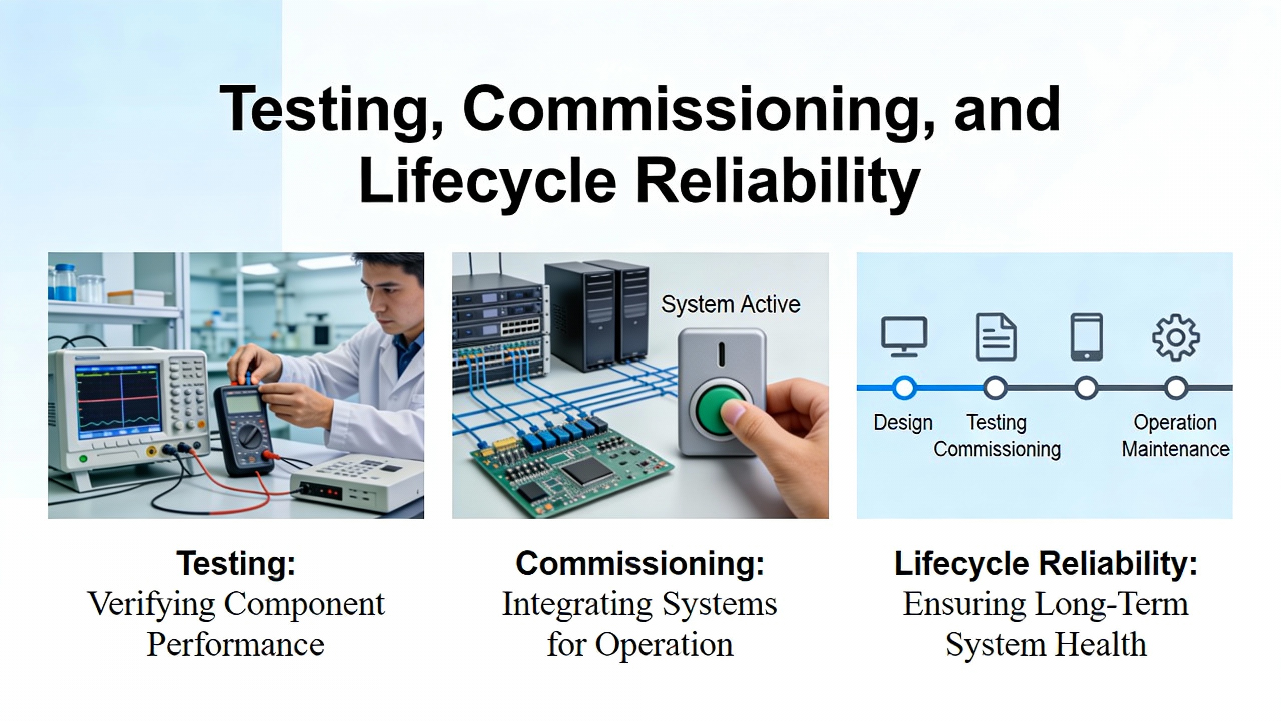
Testing, Commissioning, and Lifecycle Reliability
Across multiple sources, a common thread emerges: thorough testing and staged commissioning are essential to achieving reliable automation, especially when power protection is a key concern. Grace Automation emphasizes that hardware and software should be tested in a controlled environment before going live, under both normal and abnormal conditions. DECOWELL recommends PLC simulation tools to run logic offline, with test scenarios that include worstŌĆæcase I/O loads, communication failures, network latency, and device replacement events, and calls for documentation of test results linked to commissioning checklists.
EmersonŌĆÖs MES work highlights the value of planning Factory Acceptance Tests that verify not only individual components, such as a filter change workflow or a breaker control module, but also integrated scenarios where the process control system invokes higherŌĆælevel workflows. They note that integrated tests conducted with realistic master data, even though timeŌĆæconsuming to assemble, dramatically reduce issues during site commissioning. Qt, from its HMI perspective, advocates for continuous verification of architecture and code quality and automated UI testing to reduce manual effort and ensure reliable, userŌĆæfriendly interfaces.
The Control Engineering case study on lowŌĆætemperature reactors doubles as a cautionary tale about the cost of poor testing during design. Only when integrators tested across the full range of operating setpoints did they realize that a simple fixed or linear offset strategy would fail in midŌĆærange conditions, leading to freezing. Translated to power systems, this suggests that testing automatic transfer schemes only at nominal loads or under a single utility failure pattern is insufficient. You should test with varying load levels, different combinations of available sources, and even degraded conditions such as one UPS module offline or reduced generator capacity.
A simple mental calculation can guide expectations. If your plant has historically seen one utility disturbance requiring UPS operation per quarter and your new monitoring system reports five such events in a single month, something has changed. It might be utility quality, a misconfigured protection setting causing nuisance transfers, or a network issue that misinterprets signals. Without an architecture that captures and correlates events at the right levels, you will struggle to distinguish between real external issues and selfŌĆæinflicted problems.
Lifecycle reliability also depends on documentation and training. DECOWELL recommends inline comments in PLC code, program structure overviews, revision logs, and maintained I/O lists. Grace Automation and PanelBuilderUS emphasize comprehensive documentation of control logic, wiring diagrams, and operator manuals, along with training for operators and maintenance staff. Without these, even a wellŌĆædesigned architecture can degrade as adŌĆæhoc changes accumulate over time. Red HatŌĆÖs work on standardized architectures underscores the benefit of treating automation patterns as products that evolve with controlled changes and governance rather than as oneŌĆæoff engineering efforts.
Brief FAQ: Architecture Decisions for PowerŌĆæSensitive Automation
Where should UPS and protection logic live in the architecture?
Core UPS and protective relay logic should remain as close to the process as possible, typically within vendor controllers and dedicated PLC modules at the lower functional levels described by the Purdue model. ISA and Purdue guidance, along with practical experience, suggest that these functions must operate safely without depending on higherŌĆælevel SCADA, MES, or cloud systems. SCADA, historians, and analytics should monitor and assist but not hold veto power over essential protective actions.
How much should I rely on cloud or IIoT services for reliability improvements?
Cloud and IIoT platforms are best suited for monitoring, optimization, and fleetŌĆæwide analytics rather than timeŌĆæcritical protective functions. Cisco, Red Hat, DECOWELL, and ISA all emphasize architectures where cloud and business systems enhance but do not underpin core control. Use cloud or edge analytics to detect patterns, predict failures, and suggest configuration changes, but ensure that realŌĆætime responses to faults remain within onŌĆæpremise controllers and networks designed with proper segmentation and security.
What is the biggest architectural mistake you see in powerŌĆæfocused automation projects?
The most damaging mistake is designing as if everything will always work: assuming networks will not fail, that cybersecurity incidents will not occur, and that higherŌĆælevel systems will always be available when needed. ISAŌĆÖs resilience principles, the Control Engineering case study, and practical guidance from PanelBuilderUS and Grace Automation all point in the opposite direction. You should design your architecture so that whenŌĆönot ifŌĆöparts of the system fail, the power system remains safe, critical loads stay energized where justified, and recovery is orderly rather than chaotic.
In industrial and commercial facilities where UPS systems, inverters, and power protection equipment are the last line of defense against outages, the control system architecture you choose largely determines whether those investments deliver their full value. If you ground your design in clear requirements and risk understanding, structure it using layered functional models, apply modular and wellŌĆædocumented control logic, treat safety and cybersecurity as firstŌĆæclass requirements, and test realistically across the lifecycle, you will have an automation platform that keeps power flowing reliably while remaining ready for the next wave of digital transformation.
References
- https://arxiv.org/html/2507.09594v1
- https://graceautomation.org/industrial-control-design-and-implementation/
- https://gca.isa.org/blog/excerpt-2-industrial-cybersecurity-case-studies-and-best-practices
- https://mountainscholar.org/bitstreams/87919ae1-2854-463b-b8c6-0a84a9e035c7/download
- https://www.odva.org/wp-content/uploads/2022/06/2012_ODVA_Conference_Didier_FINAL.pdf
- https://www.researchgate.net/publication/263651475_A_Generalized_Architecture_for_Academic_and_Industrial_Automation_and_Control_via_Internet
- https://www.empoweredautomation.com/best-practices-for-implementing-automation-plc-solutions
- https://www.qidaautomation.com/How-to-design-PLC-control-system-for-industrial-automation
- https://guides.smartbuildingsacademy.com/the-ultimate-guide-to-building-automation-protocols
- http://apicsllc.com/apics/Services.html


 Videos
 News
News Applications


Leave Your Comment