Level measurement in tank farms is often treated as a local instrumentation problem. In reality, for industrial and commercial power users, it is a reliability function that sits on the critical path of plant uptime, environmental compliance, and financial performance. If your generators, boilers, or process loads depend on bulk fuel or chemical storage, your tank gauging strategy is as important to continuity of supply as your UPS or transfer switches.
Drawing on field-proven practices from oil and gas terminals, chemical plants, and power facilities, this article walks through how to think about level measurement for tank farms, how to choose the right technologies, and how to turn raw level into trustworthy inventory data you can operate on.
Why Level Measurement Matters in Tank Farms
Level measurement is simply the determination of where the liquid surface sits in a tank, but its consequences are anything but simple. Guidance from instrument suppliers and engineering firms such as Cherokee Tulsa, Ajax, and Icon Process Controls is consistent on three points: level data underpins safety, product quality, and process control across sectors from oil and gas to power generation and water treatment.
When level measurement is wrong or missing, several familiar problems appear. Overfills and spills create safety incidents, environmental releases, and regulatory exposure. Running tanks too low can cause pumps to cavitate or run dry, damaging equipment and interrupting feed to burners, scrubbers, or generators. From an inventory standpoint, poor data leads to overstocking and tied-up working capital on one side, or last-minute emergency deliveries and production stoppages on the other.
In power and reliability contexts the stakes are even higher. A tank farm might hold diesel for emergency generators, demineralized water for boilers, or critical treatment chemicals for cooling systems. If level indication fails or is mistrusted, operators fall back to conservative manual practices, frequent dipping, and wide safety margins. That translates into higher labor exposure on tank tops, more disturbance of hazardous vapors, and still no guarantee the fuel or chemical will be there when a grid event forces you onto backup power.
The message from multiple sources is clear: robust level measurement is not a ŌĆ£nice-to-have.ŌĆØ It is a core risk reduction tool that directly supports safety, uptime, and compliance.
What Kind of Measurement Do You Actually Need?
Not every tank in a farm needs the same level accuracy or functionality. A key insight from tank gauging literature is that you should distinguish among three regimes of measurement: process level, inventory control, and custody transfer.
Process and Operations-Level Measurement
Process tanks and day tanks inside a plant are usually smaller, holding from a few thousand up to roughly forty thousand gallons. For these vessels the aim is safe operation, pump protection, and basic material balance, not financial settlement. Academia-backed tank gauging work notes that typical accuracy for process tanks is on the order of about an inch of level, and this is often sufficient.
Technologies like standard free-space radar, guided wave radar, or hydrostatic level transmitters are commonly used here. Outputs are linearized to show volume, but they may not be fully corrected for temperature or density. In practice, that is acceptable when all flows are internal to the plant and the main objective is reliable control.
As an example, consider a twenty thousand gallon fuel day tank feeding generators. At that volume an inch of level might correspond to several hundred gallons. That is perfectly adequate to decide when to start a transfer pump or when to alarm on low level, as long as alarm points and pump controls are correctly engineered.
Inventory and Financial Reporting
Inventory tanks are typically larger, often in the tens to hundreds of thousands of gallons, holding products like crude, distillates, edible oils, alcohols, or solvents. In this regime, level feeds not only operations but also stock and financial accounting.
Here, error in level becomes expensive. Technical guidance points out that inventory-grade tank gauging systems can achieve level accuracy around two to three millimeters, roughly eight to twelve hundredths of an inch. Even that small error can represent about fifteen to sixteen barrels of product, close to six hundred sixty gallons. When multiplied across a twenty-tank farm and over a year, inventory misstatement quickly climbs into tens or hundreds of thousands of dollars.
To manage this, inventory systems pair accurate level measurement (often radar or guided wave radar) with temperature measurement and strapping tables, then convert to temperature-compensated volume according to standards such as API Manual of Petroleum Measurement Standards (MPMS) Chapter 7. These systems are less demanding than full custody transfer but far more rigorous than simple process indication.
Custody Transfer and Fiscal Tanks
Custody transfer tanks sit at the boundary between commercial parties or tax authorities. Examples include jet fuel storage at terminals, crude receipts to refineries, and large fixed-roof tanks holding hundreds of thousands to millions of gallons. Here, a fraction of an inch of level error can translate into thousands of gallons and substantial dollar exposure.
According to tank gauging references that follow API MPMS Chapter 3.1B, custody transfer systems target better than plus or minus one millimeter of level accuracy, about four hundredths of an inch. These installations use the most accurate level instruments available, such as free-space radar or servo gauges, combined with detailed temperature profiling, waterbottom detection, and certified calculation software.
One academic example notes that for a tank roughly one hundred feet in diameter and about thirty-three feet tall, a temperature shift of roughly two degrees Fahrenheit can change level by about four tenths of an inch, corresponding to about seventy-nine barrels or around three thousand three hundred gallons. That demonstrates why custody transfer systems must tightly control both level and temperature effects.
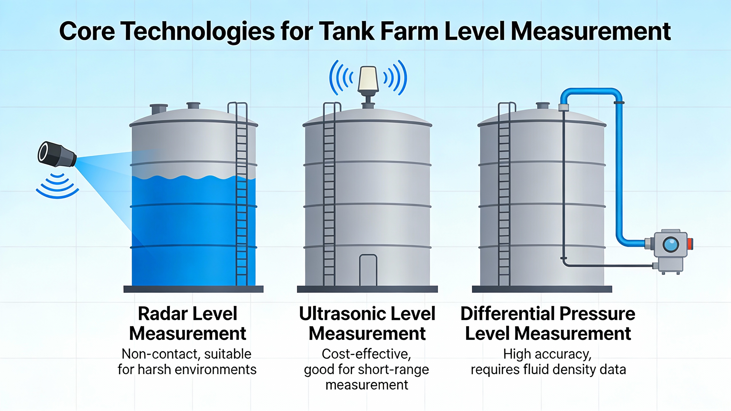
Core Technologies for Tank Farm Level Measurement
Once you know which regime each tank falls into, the next step is to select technologies that are fit for purpose. Instrument makers and engineering advisors consistently emphasize that there is no universal best method; you must match the measurement principle to the fluid, tank geometry, environment, accuracy requirement, and lifecycle cost.
Hydrostatic and Differential Pressure Level Measurement
Hydrostatic level measurement infers level from pressure at or near the bottom of the tank. In vented atmospheric tanks a gauge pressure transmitter, vented to atmosphere, effectively measures just the liquid head. In sealed or blanketed tanks, a differential pressure transmitter compares pressure at the bottom of the tank with pressure in the gas space at the top, so that the difference corresponds only to liquid height.
Sources such as Cherokee Tulsa, Instrunexus, Setra, and SKGauge highlight several strengths. Hydrostatic systems are robust, well understood, and relatively inexpensive. They are largely unaffected by surface foam or vapor and can work in turbulent or agitated liquids where some non-contact methods struggle. Submersible hydrostatic transmitters, like those described by Icon Process Controls, sit at the tank bottom and can achieve typical accuracy on the order of a quarter to half a percent, making them attractive for deep or underground tanks.
However, hydrostatic methods depend on liquid density. Variations in temperature, composition, or entrained gas change density and therefore the inferred level. In sealed tanks a single bottom-mounted gauge transmitter will report the sum of gas blanket pressure and liquid head, leading to substantial error. Setra and SKGauge therefore recommend true differential pressure measurement for pressurized or blanketed vessels, with one port connected to the bottom and the other to the top gas space.
There are also practical considerations. Wetted diaphragms can clog when liquids contain solids or sludge, and the sensor body must withstand contact with corrosive or abrasive fluids. Materials such as PVC, polypropylene, PVDF, PTFE, and 316 stainless steel are commonly used for corrosive service.
A simple example illustrates the importance of proper configuration. Suppose a sealed tank has an inert gas blanket of ten pounds per square inch gauge and a liquid head that would normally produce five pounds per square inch of hydrostatic pressure. A single gauge pressure transmitter at the bottom would read about fifteen pounds per square inch, overstating the true liquid head by a factor of three. A differential pressure transmitter subtracting the gas pressure recovers the correct five pounds per square inch equivalent and thus a valid level.
Radar Level Gauges
Radar is now the dominant technology for large petroleum and chemical storage tanks, especially where accuracy and safety requirements are stringent. Non-contact radar gauges emit microwave pulses toward the liquid surface and calculate distance from the time-of-flight of the echo. Guided wave radar sends low-energy microwaves down a probe and interprets reflections from the liquid interface.
Reports from E2G, Instrunexus, Cherokee Tulsa, Icon Process Controls, Varec, and others agree on the key advantages. Radar is largely independent of temperature, pressure, and gas composition. It tolerates vapor, fog, and even some foam. Because the sensor is mounted above the product, it avoids mechanical wear, sticking, and many corrosion issues. On large atmospheric storage tanks that were historically served by manual gauging, float-and-tape, or servo systems, non-contact radar has become the preferred choice.
High-frequency devices around eighty gigahertz, such as the ProScan series described by Icon Process Controls, produce a very narrow beam that better separates real level echoes from internal tank structures or buildup. Some models can even measure through plastic tank lids, eliminating the need for additional fittings and further reducing exposure of electronics to harsh conditions. ABBŌĆÖs guided wave radar transmitters, highlighted by Cherokee Tulsa, handle complex tank shapes and changing fluid dielectric properties.
Accuracy can be excellent. Inventory-grade systems commonly reach a few millimeters, and custody transfer radar gauges, such as the high-accuracy instruments discussed in tank gauging literature, can meet the sub-millimeter requirements of API standards. EmersonŌĆÖs Rosemount radar systems, for example, offer a dual-channel design that provides redundant, safety-integrity-level certified measurement for overfill prevention while still supporting custody transfer accuracy.
Radar is not without limits. It relies on sufficient dielectric contrast between vapor and liquid, so very low dielectric products can produce weaker echoes. There is typically a small dead zone near the antenna where level cannot be measured. Tank geometry, internal obstructions, and roof structures can create false echoes if configuration and signal processing are not carefully tuned. For challenging surfaces or internal interference, engineering firms such as SKGauge recommend radar waveguides or still pipes to constrain the signal path.
As an example, consider a large diesel storage tank one hundred twenty feet in diameter. A high-performance radar gauge with plus or minus three millimeters of level accuracy, roughly twelve hundredths of an inch, might correspond to a volume uncertainty of only a few tens of barrels. That is a small fraction of tank capacity and far better than traditional float systems whose mechanical issues can cause much larger errors.
Ultrasonic Level Measurement
Ultrasonic level transmitters operate on the same time-of-flight principle as radar but use high-frequency sound waves instead of microwaves. A transducer mounted at the top of the tank emits sound pulses, then measures the return time of echoes from the liquid surface. The method is non-contact, has no moving parts, and can be relatively easy to install.
Suppliers such as Cherokee Tulsa, Icon Process Controls, Kaidi, and Instrunexus identify ultrasonic measurement as particularly common in water, wastewater, and less critical chemical storage, as well as in sumps and open channels. Ultrasonic devices provide cost-effective continuous level monitoring where the liquid surface is relatively calm and vapors are not too heavy. Typical ranges may be on the order of ten to thirty feet, depending on model, with simple four to twenty milliamp outputs and digital protocols available.
Sensitivity to environmental conditions is the main drawback. Because sound speed depends on temperature, pressure, and gas composition, changes in those parameters can introduce error. Heavy vapors, steam, dust, turbulence, foam, and vacuum conditions can all degrade or even prevent measurement. That is why E2G notes that on large petroleum tanks radar has proven more robust and diagnostically capable than ultrasonic options.
A wastewater pumping station case described in Pumps and Systems illustrates ultrasonic strengths when properly applied. The facility suffered random pump starts and stops because an older controller misread level in a wet well. By installing a modern ultrasonic level and pump controller with improved signal processing and simple configuration through a web interface, operators achieved clean, stable level readings and reliable pump control under the same electrical noise conditions. The result was lower maintenance, reduced risk of flooding, and improved safety near homes and businesses.
Mechanical Floats, Magnetic Gauges, and Reverse Float Systems
Mechanical devices still have a role in many tank farms, particularly where visual, power-independent indication is required. Traditional float-and-tape gauges, as described by E2G, use a buoyant float inside the tank connected via tape and pulleys to a mechanical indicator at grade. These systems were among the first automatic level devices and can provide a clear local readout, but they rely on multiple moving parts that can stick, break, or wear. When later fitted with transmitters, they still suffer from the same mechanical failure modes and do not provide independent local and remote readings.
Magnetic level gauges, highlighted by Cherokee Tulsa, address some of these issues. They use a sealed float with a magnetic ring inside a side-mounted chamber. As the float rises and falls with the liquid, it drives an external shuttle or flip-flag indicator through the chamber wall. This arrangement keeps the process fluid contained, tolerates high pressures and temperatures, and provides an easy-to-read continuous level indication without power. Optional transmitters and switches can add remote outputs and alarms.
Reverse float level gauges, such as those described by Arvind Anticor, measure level from outside the tank wall. An internal float connects through a cable and pulley system to an external indicator. Because the indicator moves in the opposite direction of the float, a lower external indicator means a fuller tank. The advantage is non-contact with the chemical at the indicator, relatively simple installation, and real-time local indication that is well suited to many chemical storage tanks.
The downside of mechanical systems is also consistent across sources. Moving parts are subject to wear, fouling, and coating from viscous or dirty products. Floats can stick; tapes can break; pointers can misalign. Maintenance demands grow over time, and such gauges generally cannot reach the accuracy or diagnostic depth required for custody transfer.
Nevertheless, they remain attractive for backup indication and point-level alarms. For example, many facilities will retain a magnetic gauge for continuous local indication while relying on a radar transmitter for primary remote measurement.
Magnetostrictive and Guided Wave Radar for Interfaces and Critical Tanks
When you need precise measurement of both total level and interfaces between immiscible liquids, such as oil and water, magnetostrictive and guided wave radar technologies offer strong solutions. Cherokee Tulsa notes that magnetostrictive transmitters send pulses along a probe that interact with a magnetic float, providing high accuracy and excellent performance in the presence of foam, emulsions, and process disturbances. Guided wave radar can also resolve multiple interfaces along its probe.
DrexelbrookŌĆÖs magnetostrictive tank level system is one example tailored for oil storage. It combines level and temperature measurement on a single probe, with multiple temperature sensors along its length to provide both average temperature and a vertical temperature profile. Accuracy can reach about one hundredth of a percent on level and about one degree Fahrenheit on temperature, with explosion-proof designs suitable for hazardous locations.
In an oil tank farm, such a device can simultaneously give total level, oil-water interface level, and a detailed temperature profile. This is invaluable for accurate inventory, quality control, and detection of accumulating waterbottoms that might otherwise promote floor corrosion and leaks.
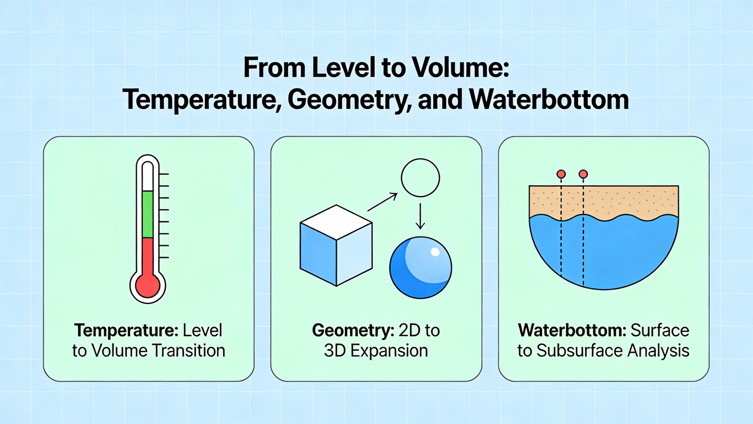
From Level to Volume: Temperature, Geometry, and Waterbottom
Measuring liquid height is only the first step toward knowing how much product you have. Converting that height into volume, and then into standardized inventory, demands attention to tank geometry, temperature, and water accumulation.
E2G and academic tank gauging references emphasize the importance of good strapping tables and proper temperature measurement. Strapping tables capture the exact relationship between level and volume for each tank, taking into account shell roundness, floor slope, and deformation. Temperature matters because most stored liquids are compressible and thermally expansive. As noted earlier, a relatively small temperature change of around two degrees Fahrenheit in a large tank can shift level by nearly half an inch, which corresponds to dozens of barrels.
Water accumulated at the bottom of hydrocarbon tanks, commonly called waterbottoms, should be measured and subtracted to obtain net standard volume. Guidance suggests using capacitance level transmitters at the bottom of tanks to detect the interface between conductive water and nonconductive hydrocarbons. These sensors can be integrated with temperature probes or servo gauges to provide complete information at the tank floor.
Consider the effect of a two millimeter level error, roughly eight hundredths of an inch, on a large tank. Tank gauging research shows that even such a small error can represent about fifteen to sixteen barrels, on the order of six hundred fifty to six hundred sixty gallons. Combined with temperature effects and imperfect waterbottom measurement, a tank farm could accumulate inventory discrepancies of many thousands of gallons if instrumentation is not carefully specified and maintained.
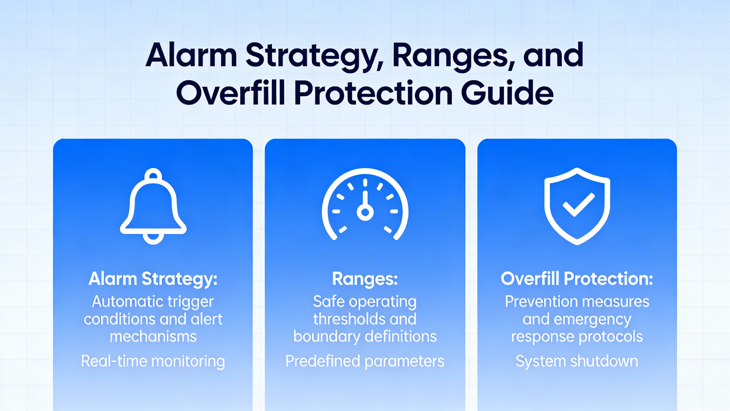
Alarm Strategy, Ranges, and Overfill Protection
Accurate level measurement is only useful if alarms and trips are thoughtfully engineered. A widely cited discussion among control professionals provides practical guidance on setting instrument ranges and alarm points.
The highŌĆōhigh level is defined as the maximum liquid level that can be tolerated before automatically stopping inflow to prevent overflow. The lowŌĆōlow level is the minimum level that can be tolerated before tripping pumps that draw from the tank to avoid cavitation or loss of suction. Between these extremes, intermediate high and low alarms should be placed to give operators enough time to react before reaching a trip point.
Importantly, instrument measurement range should extend beyond both alarm extremes. One recommended practice is to set the lower range limit roughly four inches below the lowŌĆōlow alarm and the upper range limit roughly four inches above the highŌĆōhigh alarm, as long as that upper extension does not exceed the safe, measurable height of the tank. This ensures the instrument can still read accurately when an alarm is active and avoids saturation just when you most need trustworthy data.
Alarm settings should not be chosen solely from tank dimensions. They must reflect process needs, equipment limitations, and response times. For example, in a forty foot tall tank feeding large transfer pumps, you might establish a low alarm at four feet to trigger operator action and a lowŌĆōlow at three feet where a trip will protect the pumps. The time it takes for the tank to fall from four to three feet under maximum drawdown, combined with how quickly operators and control systems can respond, will determine whether those setpoints are adequate.
Modern standards such as API 2350 for overfill prevention in petroleum facilities reinforce this systems view. They call for independent, reliable level devices for alarm and control, regular proof testing, and clear procedural linkages between level alarms and operator actions. EmersonŌĆÖs high-performance radar gauges with built-in redundancy and safety certification are examples of instruments designed to support such requirements.
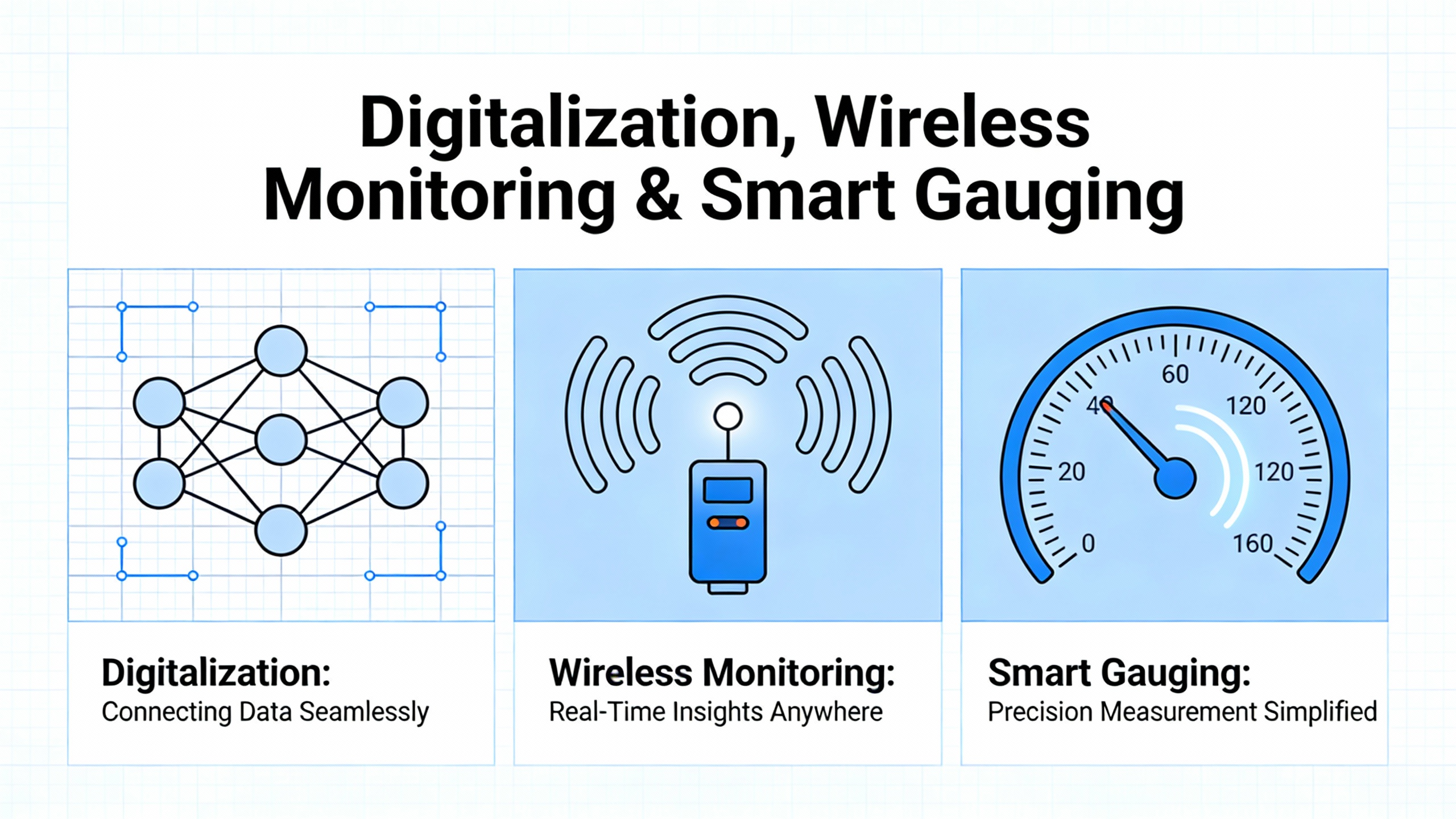
Digitalization, Wireless Monitoring, and Smart Gauging
Many tank farms, particularly older ones, still rely heavily on manual tank dipping and periodic spot checks. This approach is labor-intensive, exposes personnel to hazardous vapors and working at height, and offers limited real-time insight.
A new generation of digital and wireless solutions is changing that picture. Icon Process Controls describes wireless telemetry systems, such as cellular-based remote monitoring units, that pair with radar or submersible level sensors to provide real-time inventory data and alarms across distributed tanks. Battery-powered field units can transmit scheduled and event-driven measurements, including level, alarm status, and rate-of-consumption history, to secure cloud dashboards accessible from computers, tablets, and cell phones. Similar LoRa-based transmitters extend range in large sites and reduce the need for extensive signal cabling.
At the system level, tank gauging vendors and automation experts, including Emerson and ISA authors, highlight the move toward smart gauging platforms. These systems collect level and temperature data via digital protocols into centralized databases, then layer diagnostics, analytics, and maintenance workflows on top. Rather than relying on calendar-based maintenance, plants can shift to condition-based and predictive approaches, using real-time device health information to decide when to service or replace an instrument.
Operator dashboards built on these platforms provide at-a-glance views of instrument status, error histories, and recommended corrective actions. Some implementations support augmented reality, enabling remote experts to guide field technicians through troubleshooting steps by visually highlighting components. Instrument manuals, certificates, and calibration records can be stored in cloud libraries, accessible by scanning a code on the device.
Case studies show that such smart systems significantly reduce recurring mass-balance errors and the need for hazardous manual dipping. They also address the reality that total cost of ownership is dominated by operational costs, not initial purchase. By improving reliability and easing maintenance, smart gauging can deliver much larger lifecycle savings than any marginal reduction in upfront instrument price.
For power and reliability-focused facilities, integrating tank farm data into the same monitoring environment used for generators, UPS systems, and critical loads gives a more complete picture of readiness. You can see fuel levels, chemical inventories, and level instrument health alongside power system status, supporting better risk assessments and response planning.
Integrating Level Measurement into a Reliability Strategy
From a power systems standpoint, tank farm instrumentation is part of your protection and reliability stack. It sits alongside protective relays, UPS systems, and automatic transfer switches as a defense against interruptions and unsafe conditions.
Consider a hospital with a diesel tank farm supplying emergency generators and a separate water tank system for fire protection. If level transmitters on the diesel tanks are miscalibrated or frequently fail, the facility might assume fuel reserves are adequate when they are not. In a prolonged outage, generators could deplete fuel earlier than expected, leaving only limited UPS runtime. Conversely, if tank level is consistently underestimated, the organization may over-order fuel, tying up capital and stressing containment and venting systems.
Similarly, in a refinery or chemical plant, loss of accurate level information on feedstock and intermediate tanks can trigger conservative shutdowns or slowdowns. That protects equipment but compromises throughput and may cause power systems to operate in abnormal configurations. In extreme cases, overfills or pump run-dry events can damage motors and drives, injure personnel, and take critical assets offline for extended repairs.
Reliable level measurement and inventory management support reliability in three key ways. First, they enforce safe operating envelopes, preventing overfill events and protecting pumps and rotating equipment. Second, they improve planning, ensuring critical materials like fuel and treatment chemicals are available when needed, which in turn stabilizes process and power demand. Third, smart gauging systems with predictive diagnostics reduce unplanned maintenance work on dangerous tank tops, freeing resources to focus on higher-value reliability improvements elsewhere.
From a design perspective, it is worth treating level instrumentation on critical tanks the same way you treat key power protection devices. This may include using redundant transmitters, providing power from resilient sources or loop-powered circuits backed by UPS, and integrating alarms into central supervisory systems rather than leaving them as standalone local indicators.
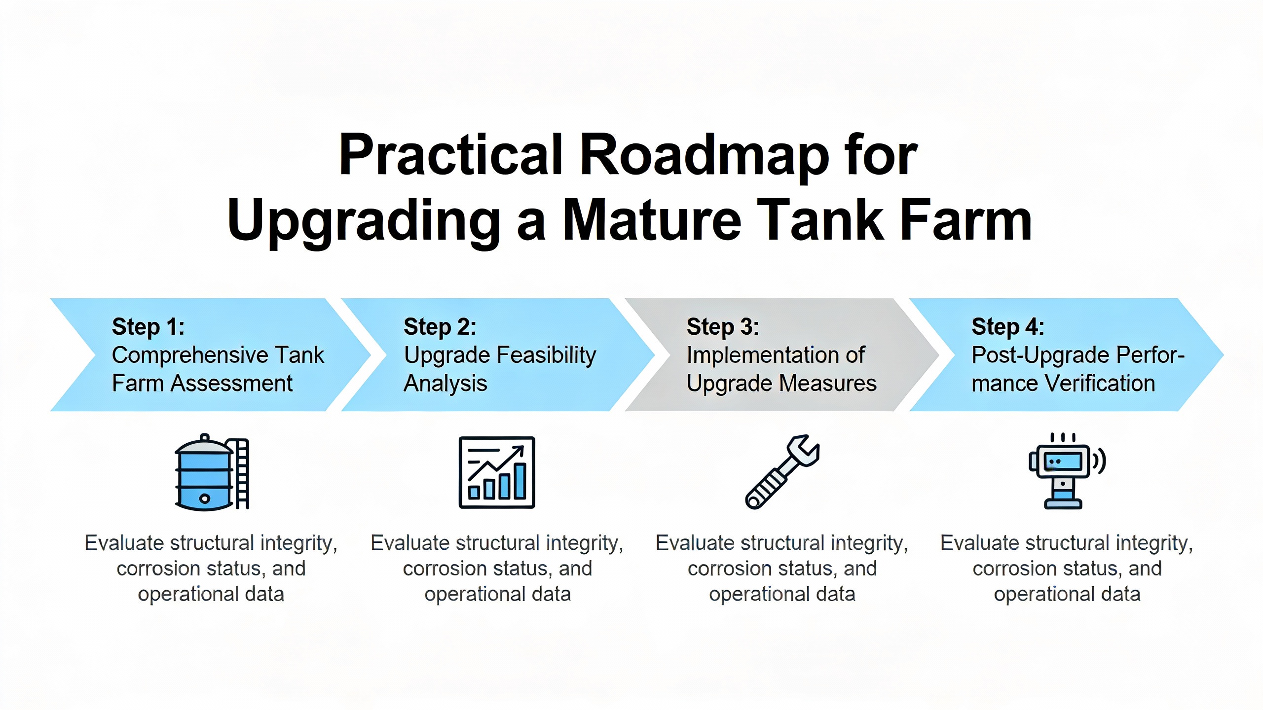
Practical Roadmap for Upgrading a Mature Tank Farm
Many bulk storage facilities, especially those built in the middle of the last century, still operate with a mix of manual gauging, aging float systems, and limited remote visibility. E2GŌĆÖs analysis of ŌĆ£matureŌĆØ atmospheric storage tanks highlights typical challenges: limited or poorly located nozzles, outdated communication infrastructure, and constraints from environmental regulations on modifying roofs or adding still pipes.
A practical upgrade path begins with a structured assessment. Identify which tanks already have automatic level instrumentation, which rely on manual methods, and which are most critical from a safety, environmental, or reliability standpoint. Document available nozzles and still pipes, along with any restrictions on modifications imposed by regulators or standards. Evaluate how far and through what path you can bring new signals back to control rooms, or whether wireless solutions might avoid extensive trenching and conduit.
Next, match technologies to specific tanks and fluids. For large hydrocarbon tanks, non-contact radar is generally the preferred primary level technology, possibly with redundant gauges for critical service. For corrosive chemical tanks with limited access, high-frequency radar that can mount on standard top fittings or even measure through plastic walls can minimize intrusion. Smaller or underground tanks may be well served by submersible hydrostatic transmitters. Mechanical indicators can remain as backup local displays, but should not bear primary responsibility for high-consequence measurements.
Finally, design alarm and overfill protection functions with both continuous instruments and independent point-level devices. API tank gauging and overfill standards, combined with vendor guidance, recommend pairing continuous level gauges with separate highŌĆōhigh switches where overfill consequences are significant. Modern radar systems with diagnostic and safety certifications, together with smart gauging software, make it easier to implement these strategies without completely overhauling existing infrastructure thanks to signal emulation and wireless options.
FAQ
Do I really need radar on every tank in a farm?
Not necessarily. Radar excels on large tanks with high financial or safety consequences where its non-contact, high-accuracy performance shines, such as crude, refined product, or critical chemical storage. For smaller process tanks or less critical services, hydrostatic transmitters or even ultrasonic devices may be entirely adequate and more cost-effective. The selection criteria emphasized by Cherokee Tulsa, Icon Process Controls, Kaidi, and SKGauge all point in the same direction: match the instrument to the medium, tank geometry, environment, and required accuracy, rather than applying a single technology everywhere.
How often should level instruments be calibrated or verified?
There is no single interval that fits every installation. However, best practices from instrument suppliers and smart gauging case studies suggest a move away from fixed calendar intervals toward condition-based verification. Modern radar, ultrasonic, and hydrostatic devices offer diagnostics that can flag drift, weak echoes, buildup, or process changes. Periodic proof tests are still required for safety systems, but routine calibration can often be extended when diagnostics confirm stable performance. For critical custody transfer tanks, calibration and verification must follow applicable API and metrology standards, regardless of apparent stability.
How should level data be integrated with power and reliability systems?
For facilities where bulk storage feeds generators, boilers, or other critical loads, level data should appear in the same supervisory environment used for power systems. That means integrating tank gauging outputs into SCADA, distributed control systems, or dedicated reliability dashboards where operators monitor UPS status, switchgear, and generator health. Wireless telemetry and IIoT-ready instruments, as described by Icon Process Controls and ISA, make it easier to bring remote tank data into these systems without extensive cabling. The goal is to give operations and reliability teams a single, coherent view of both energy and material reserves so they can plan and respond effectively during abnormal events.
Reliable level measurement in tank farms is not just about knowing how full a tank is. It is an essential part of how you protect people, the environment, and the continuity of your power and process systems. Treat your tank gauging strategy with the same rigor you apply to your UPS, generators, and protection relays, and your entire facility will be more resilient when it matters most.
References
- https://www.academia.edu/37356566/Tank_gauging
- https://dr.lib.iastate.edu/bitstreams/29c4f0f7-60a3-4197-aaf9-123e4be15845/download
- https://epubl.ktu.edu/object/elaba:138802962/138802962.pdf
- https://petex.utexas.edu/images/book_previews/Primer_Oil_Gas_Measurement_previewwtrmrk.pdf
- https://openscholar.uga.edu/record/21793/files/B1152-07.pdf?register_download=0
- https://digital.library.unt.edu/ark:/67531/metadc739661/m2/1/high_res_d/798045.pdf
- https://www.isa.org/intech-home/2022/december-2022/features/smart-gauging-systems-improve-tank-farm-efficiency
- https://www.kaidi86.com/choosing-level-indicators-for-tank-farms-and-terminals.html
- https://www.pumpsandsystems.com/4-ways-level-devices-improved-accuracy-system-reliability
- https://www.ajax-sol.com/post/why-tank-level-measurement-matters-ensuring-efficiency-and-safety-in-industrial-processes


 Videos
 News
News Applications


Leave Your Comment