Industrial and commercial power supply systems live or die on their controls. You can invest in the best UPS modules, inverters, static transfer switches, and distribution gear, and still end up with nuisance trips, unexplained transfers to bypass, or unsafe maintenance conditions if the control system is poorly specified.
In practice, most painful UPS and power protection failures I see trace back to gaps in the specifications and documentation: missing alarm definitions, unclear control ownership between platforms, vague sequences of operation, or undocumented interlocks. Experienced ISA contributors such as Hunter Vegas, Hector Torres, and Greg McMillan have stressed that documentation is not an afterthought; it is the backbone of a reliable control system over the entire lifecycle, from design through maintenance. The same lesson appears across integrator guidance from the Control System Integrators Association (CSIA), Malisko, CSE Magazine, and others.
This article organizes those field-tested lessons into a structured overview of control system specifications for UPS, inverters, and power protection systems. The focus is practical: what you need to specify, why it matters, and how to make sure your documentation actually supports safe, reliable operation ten years after startup.
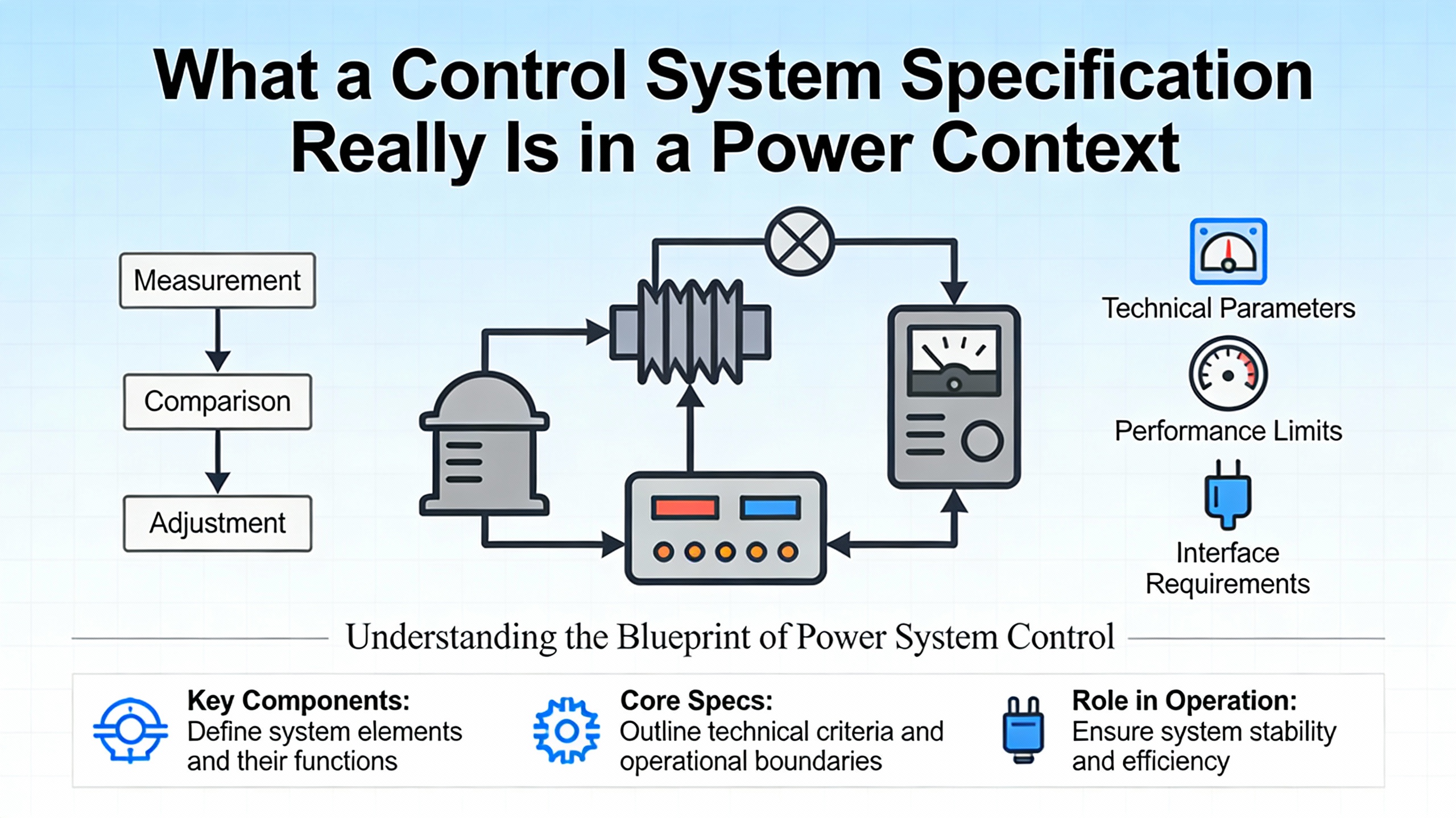
What a Control System Specification Really Is in a Power Context
In power systems work, the phrase ŌĆ£specificationŌĆØ is often used loosely. One person means a purchase spec for a UPS; another means a short controls narrative; a third means a full System Requirement Specification. It helps to distinguish the major document types and make them work together rather than compete.
MaliskoŌĆÖs work in process industries lays out a hierarchy that maps surprisingly well to power protection projects. At the top sits the User Requirements Specification. This is written by stakeholders to describe what the system must achieve, in business and operational terms. For a UPS plant, the URS would spell out required load protection levels, acceptable transfer behaviors, ride-through time, monitoring expectations, and any regulatory or corporate requirements that must be met.
From there, process or facility engineers create a Process Narrative and often a Process Flow Diagram to describe how the power system is intended to behave in plain language. In a UPS context, this narrative explains how normal power flows, how backup power engages, what happens during maintenance bypass, and how different operating modes transition. Consulting articles from Malisko emphasize that this narrative should be accessible, not just a collection of device tags.
The Sequence of Operations then translates that narrative into step-by-step behavior. CSE Magazine calls this a control philosophy or sequence of operation and highlights it as foundational. For power systems, this includes startup sequences, transfer criteria between sources, load-shedding steps, inverter synchronization rules, and what each system does on faults or loss of communication.
Controls engineers then prepare a Functional Specification, which Malisko describes as the document that explains how each requirement will be fulfilled in practice. That means mapping UPS, inverter, and switchgear behavior into control strategies, interlocks, alarm logic, and detailed sequences, including which platform owns which logic: PLC, UPS controller, building automation system, or SCADA.
Alongside the Functional Specification, a Technical Specification or design specification captures the ŌĆ£howŌĆØ in detail. Guidance from monday.com on technical specs, and Jama Software on System Requirement Specifications, reinforces that a good technical spec covers system behavior, constraints, architecture, security, rollout, and maintenance. For a power protection system, that includes controller platforms, redundancy strategy, communication networks, cyber safeguards, performance targets, testing, and support.
Finally, Malisko and Jama describe Detailed Design Specifications and subordinate documents. Software Design Specifications describe software packages, coding approach, user interfaces, databases, and detailed control logic. Hardware Design Specifications define servers, PLCs, networks, and control panel architectures. A traceability matrix ties all of these back to the URS so that every control behavior in the PLC and HMI can be traced to a user need and verified in testing.
One useful way to see the relationships is to compare scope and audience.
| Document Type | Main Audience | Primary Focus in Power Systems |
| User Requirements Specification | Owners, operations, safety | What the UPS and protection system must achieve: protection levels, ride-through, uptime, compliance |
| Process Narrative and Sequence of Operations | Process/facility engineers, controls engineers, integrators | How the power system behaves in each mode and scenario, described in plain language |
| Functional Specification / Safety Requirements Specification | Controls engineers, safety specialists, reviewers | Detailed description of control and protection functions, inputs, outputs, interlocks, safe states |
| Technical / Design Specification (DDS, SDS, HDS) | Controls designers, panel builders, IT/OT, cybersecurity | How the system will be built: platforms, networks, coding approach, HMI/SCADA design, hardware details |
| System Requirement Specification and Traceability Matrix | Project managers, QA, regulators, auditors | Traceability from requirements to design, tests, and acceptance; impact analysis for changes |
The key is not to chase perfection in a single document. As ISA experts argue when discussing control-system documentation, the format should evolve through the lifecycle. Project-focused spreadsheets and drawings are appropriate in design and FAT; concise, maintenance-focused data is better in operation. What matters is that each document is complete for its purpose and that relationships between them are clear.
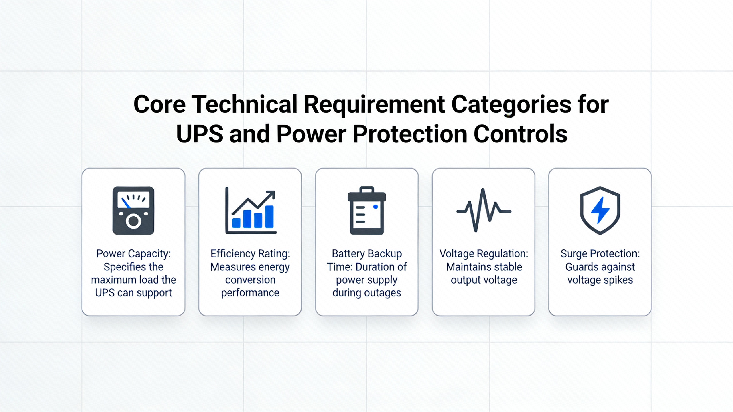
Core Technical Requirement Categories for UPS and Power Protection Controls
Once you understand the documentation landscape, the next step is to define the technical requirements that materially shape reliability, cost, and maintainability. Practical guidance from PLC-focused resources and integrator best practices highlights several recurring categories that deserve special attention in power projects.
Platforms, Architecture, and Redundancy
PLCDesignŌĆÖs overview of technical requirements for PLC and DCS systems stresses that platform and architectural choices dominate cost and complexity. In power protection, that is doubly true because many owners expect high availability comparable to process safety systems.
Specifications should clearly state approved manufacturers for PLCs, DCS, SCADA, and HMI workstations. That may seem like a procurement detail, but it directly affects available function blocks, redundancy options, and support. PLCDesign notes that such constraints can heavily shape hardware choices, and in practice, they also influence how easily your system integrates with the UPS and inverter vendor controllers.
Redundancy requirements must be explicit. The PLCDesign guidance highlights the need to define whether CPUs, I/O, networks, and servers are redundant and what Safety Integrity Level or similar target is required. For a critical UPS plant serving, for example, a large data center or hospital, you may need redundant PLCs supervising key transfer and load-shed logic, dual communication paths to inverters and static switches, and redundant SCADA servers. If those expectations are not captured early, they often get value-engineered away or bolted on later at much higher cost.
Architectural requirements also include how many controllers are needed, where they are located, how many I/O points are local versus remote, and what communication speeds are required to coordinate UPS systems, inverters, generator controls, and building automation systems. PLCDesign emphasizes that the counts and distribution of controllers and I/O, and the way they communicate with third-party systems, are central to the architecture. In a multi-module UPS system, for instance, you may deliberately allocate one PLC per electrical room plus a supervisory controller, and the spec should say so.
A practical example helps. Suppose your critical load is around 400 kW and you plan three UPS modules in parallel, each with its own internal controller plus a supervisory PLC coordinating bypass and static transfer switches. Your specification should not just say ŌĆ£redundant controls.ŌĆØ It should state whether the PLC is redundant, how it monitors module status, whether it can safely transfer load if one module controller fails, and how it behaves if network communication is lost. Those points determine whether a controller fault becomes merely an alarm or a real threat to uptime.
HMI, SCADA, and Operator Visibility
PLCDesign also highlights HMI and SCADA requirements as a major category. For power systems, this ranges from simple local panels on UPS modules to fully integrated SCADA for a large campus or industrial facility.
Technical requirements should call out the type of operator workstations, the number of screens or monitors, and the scope of graphics and alarms. PLCDesignŌĆÖs examples include sequence-of-events resolution, history and alarm handling, backup, access management, and counts of communications I/O. Translating that to power systems, you want to specify how finely you will time-stamp events like breaker trips and UPS transfers, how much historical trend data you store for load profiles and battery states, and what alarm grouping and filtering rules are needed to keep operators from being overwhelmed during a disturbance.
ISA practitioners recommend against cluttering P&IDs with every detail and instead emphasize readable operator graphics linked to accurate documentation. In a UPS plant, this means HMI screens that clearly show power paths, source status, battery conditions, and transfer availability, with each measurement and switch tied back to a unique tag in the taglist. A high-quality taglist, as emphasized in ISA guidance, underpins everything else by providing unique tag numbers that tie graphics, I/O configuration, and documentation together.
A simple calculation shows why getting this right matters. If your system has 250 digital I/O points and 80 analog signals across UPS, switchgear, and supporting systems, and you add typical diagnostic points and spare channels, you might easily manage over 400 tags. With a well-structured taglist that includes ISA prefixes, ranges, locations, and loop sheet references, as recommended by ISA experts, maintaining and expanding that system is manageable. Without it, every change becomes a small detective project.
Performance and Control Strategy
Foundational control-system guidance from CSD & Integration, Inc. and Turner Integrated Systems reminds us that behind every industrial control system are the same basic elements: inputs, controlled processes, sensors, outputs, and controllers. For UPS and power protection systems, the controlled process is the flow of electrical power and the protection of connected loads; the inputs are operator commands, automatic transfer criteria, and external signals; the outputs are breaker operations, inverter mode changes, and alarms.
Specifications must decide whether key behaviors rely on open-loop logic or closed-loop feedback. Open-loop logic might be sufficient for some transfer criteria based solely on breaker status and source availability. Closed-loop behavior is essential wherever feedback from sensors drives corrections, such as regulating output voltage or frequency. Turner Integrated Systems emphasizes that effective design begins with a clear understanding of system goals and identification of all variables to be controlled, followed by modeling and simulation before committing to programming.
ControlSystemsDesignŌĆÖs overview of basic control elements explains the role of sensors and feedback. In power systems, this translates into requirements for voltage, current, temperature, and status sensors that confirm tasks are completed and trigger subsequent actions. On-off control principles appear in simple interlocks and permissives, while feedback control principles apply to more sophisticated inverter and regulator behavior. Your specifications should be clear about which signals are merely for indication and which feed closed-loop protective or regulatory logic.
A useful example is ride-through time. If a facility requires that critical loads remain supported for at least 10 minutes after loss of utility power before starting load shed, that requirement should appear in the URS and be carried through to the Functional Specification. For a 400 kW critical load, that implies at least 4,000 kW-min of usable stored energy. It also drives control behavior: the control system must monitor battery state, estimate remaining time, and trigger staged responses such as starting generators or shedding noncritical loads according to the Sequence of Operations.
Safety and Protection Requirements: From Hazards to Safe States
When power systems go wrong, the consequences range from equipment damage to life safety issues. The control system specification needs to handle this with the same rigor that process industries apply to safety instrumented systems.
A widely used pattern from functional safety guidance, summarized in control.com discussions on Safety Requirements Specifications, starts with a clear Process Description. For a safety-related control system, this includes P&I diagrams and a list of materials and properties that affect safety or reliability, such as corrosion, plugging, coating, or extreme temperatures. In power systems, the analogous description should point out conditions such as high fault currents, arc-flash energy, and thermal stresses that influence protective behavior.
The Hazards section then identifies each hazard and defines the required safety functions, the intended layers of protection, and the robustness required. Control.com contributors stress that timing constraints must be captured here, because they drive design choices. Their example contrasts a tank that takes 20 minutes to overflow after a high-level alarm with a boiler that can reach an explosive mixture in about 5 seconds. In power protection, the difference between a slow-developing overload and a near-instantaneous short circuit plays a similar role. Your specification should clearly state how quickly the safety system must act for each scenario.
Field Devices must receive specific attention. The control.com guidance recommends documenting all sensors and final control elements associated with each hazard, and considering issues such as sensor drift or valve coating that affect reliability. In electrical protection, the parallel concerns are sensor accuracy, saturation under fault conditions, and contact wear. Oversized actuators can create hazards in process systems; similarly, misapplied breakers or contactors can create unsafe conditions if they fail to interrupt as intended. Capturing these concerns in the safety-related part of your specification ensures they are addressed in design rather than discovered during commissioning.
A well-written Operating Cycle and Safe States section describes operating modes and the actions required to reach or maintain safe states, providing the framework for detailed protective functions. For a UPS plant, safe states might include transferring to bypass with alarms, shedding noncritical loads, or shutting down parts of the system while keeping essential loads energized.
The Safety Functions section then describes, in concrete detail, how the system behaves for each hazard: which sensors participate, what logic is applied, which outputs are affected, and what timing or performance limits apply. Control.com contributors recommend that this section also describe any situations where protections are temporarily disabled or modified, such as during maintenance or testing.
The operator interface is part of safety. The specification should define required operator actions, the location and format of controls and indications, and any time limits for operator response. Control.com guidance ties these actions to different stages of the operating cycle, such as startup and routine monitoring. In a UPS installation, that might mean specifying local emergency shutdown stations, acknowledgement rules for critical alarms, and clear indications of current power source and protection status.
Finally, maintenance and testing requirements must be explicit. The Safety Requirements Specification guidance calls for provisions that let technicians test safety functions safely, control risky practices such as leaving test jumpers in place, and state when test frequency is used to achieve a target integrity level. In power protection systems, this translates to requirements for periodic transfer testing, verification of alarms, and validation of remote shutdown or block features, supported by proper documentation so that technicians can work without improvising.
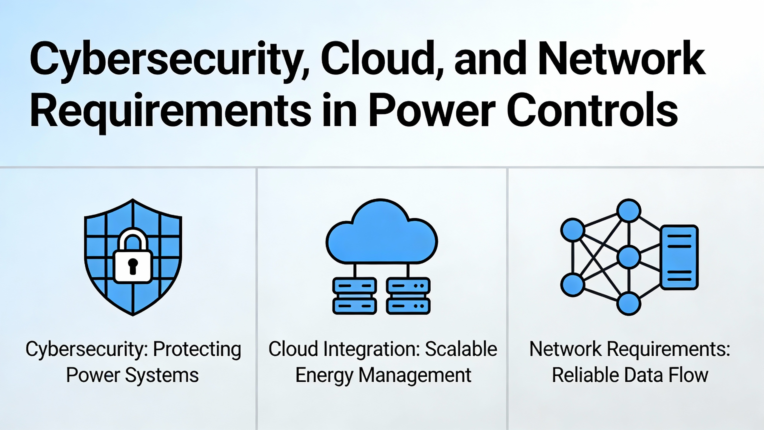
Cybersecurity, Cloud, and Network Requirements in Power Controls
Modern UPS and power protection systems are almost never standalone. They are tied to SCADA, building automation, remote monitoring platforms, and sometimes cloud analytics. That connectivity brings both value and cybersecurity risk, and your technical specification must treat cyber requirements as first-class technical requirements rather than a late addition.
CSIAŌĆÖs Best Practices Manual, updated in mid-2024, emphasizes alignment with contemporary cybersecurity standards such as ISO 27001 and the NIST Cybersecurity Framework. The updated content makes clear that integrators are expected to safeguard both their own information assets and those of their customers, including sensitive technical, operational, and business data. For power systems, that data includes configuration backups, network addressing details, alarm logs, and sometimes remote access credentials for UPS or inverter vendor support.
The CSIA updates also highlight cloud services as a central part of modern integrator IT environments, and encourage managing cloud security with the same rigor as on-premise systems. If your UPS monitoring or event analysis uses cloud-based dashboards, the control system specification should state allowed cloud platforms, required access controls, expectations for configuration management, and responsibilities for vendor management.
CSE MagazineŌĆÖs guidance on successful controls integration adds another layer: network design must be intentional, with IT and cybersecurity needs considered from the start. They recommend assigning VLANs, IP addresses, and access levels early, and separating critical control traffic from monitoring-only devices. In practice, that means specifying distinct network segments for PLCs and protection relays, HMI/SCADA, remote monitoring gateways, and corporate access, and defining which traffic is allowed between them.
Technical specification guidance from monday.com reinforces the importance of governance for technical documents themselves. Organizations are advised to control access to specs, manage versions, and use specification management tools so that sensitive technical information stays protected even while teams collaborate. Jama Software makes a similar point about tools for System Requirement Specifications: they should support traceability, change impact analysis, and risk visibility across the lifecycle.
In a UPS plant, these ideas combine into concrete requirements such as authenticated remote access for support, role-based access to HMI and engineering tools, secure storage of configuration backups and traceability data, and clearly documented firewall rules between control networks and the broader enterprise. While the exact technologies may change over time, the expectation that cybersecurity controls be aligned with current standards and regularly revisited is a recurring theme in CSIAŌĆÖs and CSE MagazineŌĆÖs guidance.
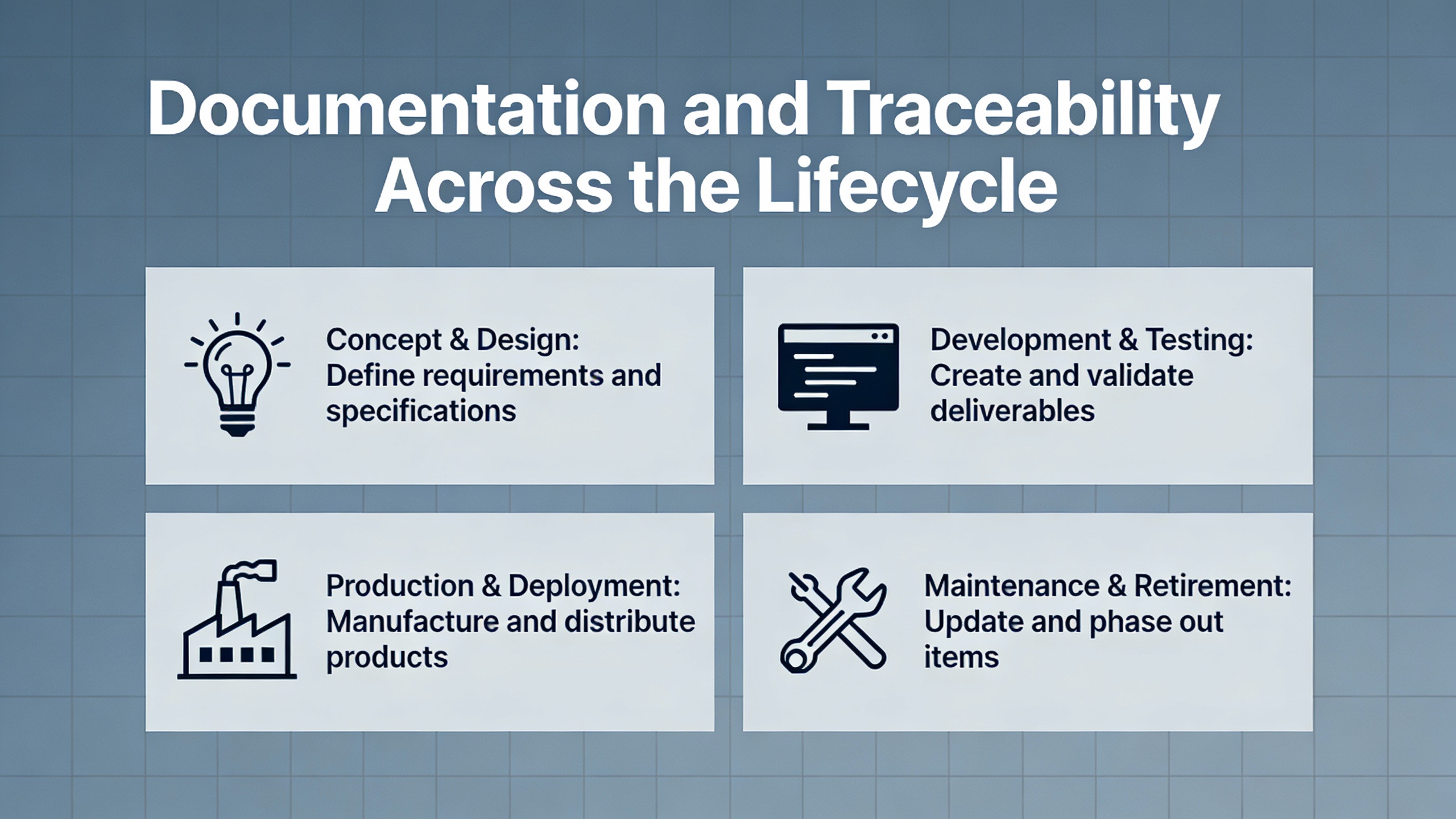
Documentation and Traceability Across the Lifecycle
Technical requirements alone are not enough; they must be backed by documentation that is both rigorous and usable. ISA contributors devote substantial attention to documentation practices precisely because poor documentation leads to long-term problems in operation and maintenance.
They describe the taglist as the foundational document: a complete list of every instrument and device in the plant, including local gauges and relief valves where applicable. In a power system, that translates to a taglist covering UPS modules, inverters, static transfer switches, breakers, sensors, and monitoring devices. Well-designed taglists use structured columns such as prefix, tag number, area, loop description, device description, control system location, ranges, and cross-references. On large projects, ISA practitioners extend the taglist with configuration details such as alarm limits, control directions, filtering, historian settings, and simple interlock descriptions. This allows auto-generation of portions of the control code and provides objective progress metrics during configuration and testing.
P&IDs are another cornerstone. OSHA requirements effectively force plants to maintain them, and ISA guidance suggests they should be the primary process drawing. However, the advice is to avoid cluttering P&IDs with every device detail; instead, they should show key valves, fail positions, and brief I/O notations, supported by written notes that document both hardwired and major software interlocks. For a UPS and power distribution system, the equivalent is a one-line or schematic that clearly shows source, UPS, and load relationships, with enough annotation to support hazard analysis and safety studies such as HAZOP and safety integrity evaluations.
Flow charts are recommended to document complex sequences, such as batch recipes in process plants. The same technique applies to power systems for sequences like automatic transfer on utility loss, generator startup and synchronization, or staged load shedding. High-level charts describe main modes and transitions; detailed charts describe each step. ISA experts note that such charts support design, configuration, Factory Acceptance Testing, and remain useful for hazard studies through the system life.
Loop sheets and field wiring diagrams matter greatly for maintainability. Despite occasional claims that loop sheets are unnecessary, ISA practitioners argue they are critical in the field because technicians can find a drawing from a loop tag alone. For power systems, loop sheets and termination diagrams help technicians trace signals from a voltage or current sensor through junction boxes and marshalling panels to PLC or SCADA hardware, including fuses and power sources. Field wiring diagrams also help locate and assign spare cable pairs or network drops during expansions.
MaliskoŌĆÖs lifecycle documentation (URS, FS, DDS, FAT, SAT, IOQ) and JamaŌĆÖs view of SRS as the central reference reinforce the value of traceability. A traceability matrix connects URS requirements to design elements, tests, and qualifications. Jama notes that such tools support impact analysis when requirements change and provide visibility into risks. In power projects, this means you can see, for example, which tests validate ŌĆ£no single controller failure shall cause loss of UPS protection,ŌĆØ and which HMI and PLC logic implement that requirement.
Finally, CrosscoŌĆÖs programming best practices advocate keeping supporting documentation close to the code. They suggest that functional requirements and design notes can be stored in lightweight formats, such as spreadsheets, ideally within or tightly coupled to the program archive. For a UPS control project, that might mean embedding taglists, interlock tables, and alarm definitions in version-controlled repositories alongside PLC and HMI code. This approach reduces the risk that documentation diverges from the actual implementation.
A simple real-world scenario illustrates the benefit. Imagine a maintenance technician responding to an unexpected transfer to bypass on a UPS system. If the taglist is complete, P&IDs and one-lines are up to date, and loop sheets clearly show wiring and ranges, the technician can trace the problem from the alarm on the HMI back to the sensor or interlock in a matter of minutes. Without those documents, troubleshooting can stretch into hours, sometimes with unnecessary component replacements and downtime.
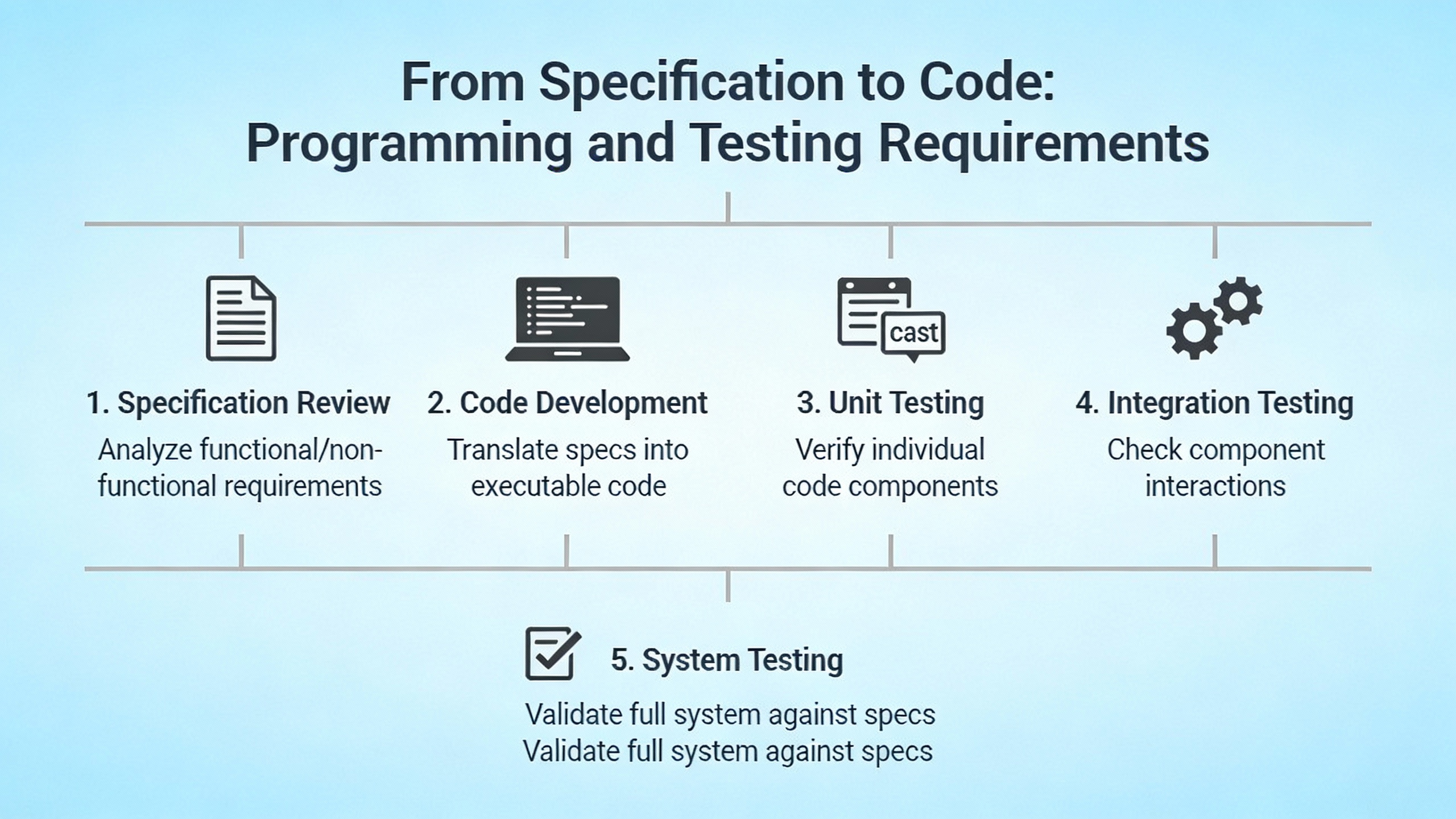
From Specification to Code: Programming and Testing Requirements
Specifications become reality through code and configuration. If programming practices are inconsistent or poorly documented, even a beautifully written specification will not deliver the reliability you expect.
CrosscoŌĆÖs guidance on control system programming emphasizes that projects should begin with a clearly defined structure for both controller and HMI code. This structure is often laid out in diagrams or in-code legends that map major functions, variables, and segmentation. In a power protection project, the specification should require such a structure, for example, by calling for separate program sections for input processing, interlocks, automatic transfer logic, operator commands, alarm handling, and communication.
Supporting documentation for functional requirements and programming standards is essential, but Crossco notes that it can be lightweight. What matters is that it exists and remains accessible. They recommend planning for future expansion by segmenting memory and functions with sufficient headroom, testing designs on paper, and reviewing concepts with experienced peers while avoiding overbuilding features that are out of scope.
Understanding system resources is another Crossco theme. They suggest deliberate loading tests with expanded applications to find performance limits before adding overhead. For power systems, that might mean testing worst-case alarm storms and communication traffic between UPS controllers, PLCs, and SCADA to ensure CPU, memory, and network capacity are sufficient. Specifications can require such performance testing as part of Factory Acceptance Testing.
Reusable, generalized function libraries are strongly recommended. Rather than hard-coding repeated logic for each UPS module or breaker, common routines for interlocking, alarm handling, and status evaluation should be called with parameters. Crossco points out that this approach reduces memory use, speeds processing, and makes later modifications less error-prone. The specification can encourage this by requiring reusable libraries and defining coding conventions.
Consistency is a recurring theme. Crossco urges teams to stick to chosen design methods, patterns, and tag naming across the entire control system, and to avoid experimenting with multiple approaches inside the same application. CSE MagazineŌĆÖs integration guidance aligns with this, emphasizing standardized signal naming and documentation (for example, following ISA 5.1 or site standards) across P&IDs, I/O lists, wiring diagrams, and PLC code.
Testing and commissioning tie everything together. PLCDesign and Malisko both highlight the importance of Factory and Site Acceptance Testing, while CSE Magazine advocates integrated commissioning that tests control sequences at the system level, including abnormal scenarios such as sensor failures and power loss. The specification should define which tests are performed at FAT, which at SAT, how safety functions are validated, and what constitutes acceptance. MaliskoŌĆÖs references to Installation and Operational Qualification in regulated industries show how formal this can become; even in less regulated environments, clear FAT and SAT requirements are crucial.
A simple calculation can help scope testing. If your UPS project involves around 300 I/O points, and you plan to test each point for correct wiring, scaling, and alarming, plus run, say, 20 scenario tests for sequences and failure modes, that can easily translate into several hundred individual test steps. Capturing those steps in a test plan derived from the specification makes the effort predictable and repeatable rather than ad hoc.
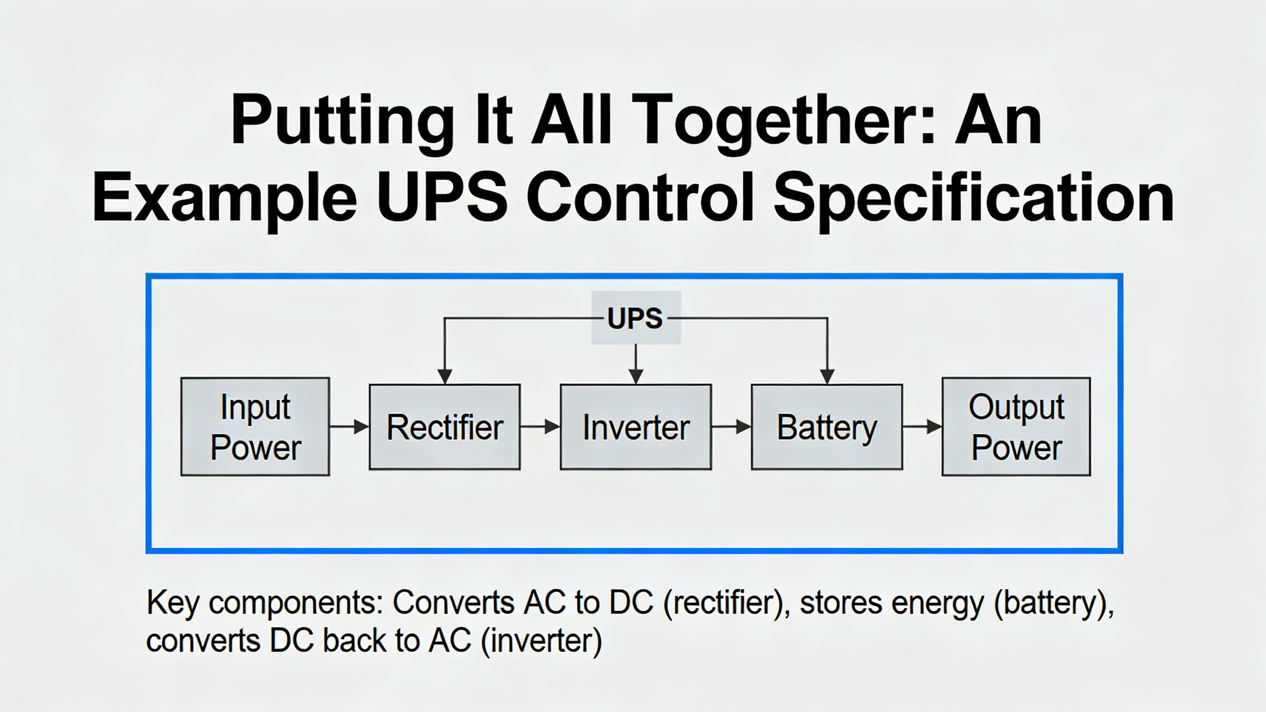
Putting It All Together: An Example UPS Control Specification
To see how these principles work in practice, imagine a medium-size industrial facility adding a new UPS plant to protect critical process loads. The plant includes multiple UPS modules, inverters, static transfer switches, and upstream and downstream breakers, all supervised by a PLC-based control system and integrated into an existing SCADA.
The project begins with a User Requirements Specification that defines target uptime, acceptable transfer behaviors, ride-through times, alarm and event visibility, and any corporate or regulatory requirements. Drawing on MaliskoŌĆÖs guidance, the URS distinguishes between critical and noncritical loads and specifies, for example, that critical loads must ride through at least 10 minutes of utility loss before load shedding is considered, and that operators must be able to see event timelines with millisecond-level resolution for investigations.
Process and facility engineers develop a Process Narrative describing normal operation, transfers between sources, and maintenance scenarios like operating on bypass or isolating a UPS module. They create flow diagrams that map normal, maintenance, and fault paths for power, an approach consistent with ISA recommendations for using flow charts and readable schematics.
A Sequence of Operations details startup, transfer, and shutdown behavior. Following CSE MagazineŌĆÖs advice, conditions are written with specific numeric thresholds and clear criteria: under what conditions the system attempts automatic retransfer to normal power, what interlocks prevent unsafe transfers, and what the system does on loss of communication between the PLC and UPS modules.
Controls engineers translate these into a Functional Specification and a Safety Requirements Specification. Using patterns from control.comŌĆÖs functional safety discussions, they identify hazards such as loss of redundancy, failure to transfer, and unsafe maintenance states. For each hazard, they define safety functions, layers of protection, timing requirements, and safe states. For example, they specify that if the system detects conflicting breaker statuses or unsafe power paths, it must inhibit automatic transfers and alert the operator rather than risk backfeeding.
Technical specifications define the hardware and software architecture following PLCDesignŌĆÖs categories. They state the approved PLC platform, required CPU and network redundancy, distribution of I/O between local control panels and marshalling cabinets, and communication protocols with UPS and inverter controllers. HMI and SCADA requirements include the number and type of operator workstations, sequence-of-events resolution, historian depth, alarm grouping, and access management.
Cybersecurity requirements draw on CSIA and CSE Magazine. The specification calls for distinct VLANs for PLCs, HMI/SCADA, and remote monitoring gateways, controlled access between these networks, and managed use of any cloud-based monitoring services with explicit responsibilities for configuration and vendor management. Access control and backup practices for configuration data are aligned with ISO 27001-style expectations and the NIST Cybersecurity FrameworkŌĆÖs risk-based approach, as described by CSIA.
Documentation and traceability are embedded from the start. Engineers build a comprehensive taglist as ISA experts recommend, linking each tag to ranges, hardware locations, and loop sheets. A traceability matrix connects URS requirements to specific PLC logic modules, HMI screens, and FAT/SAT test cases, in line with MaliskoŌĆÖs and JamaŌĆÖs guidance.
Programming standards follow CrosscoŌĆÖs best practices: a defined structure for PLC and HMI code, consistent tag naming, generalized function blocks for repeated logic, and deliberate load testing to confirm performance margins. Temporary or staging logic is organized and later cleaned up, preventing clutter and confusion.
FAT exercises both individual I/O and full sequences, including abnormal scenarios like loss of a UPS module, sudden utility return, or communication failure, following CSE MagazineŌĆÖs recommendation for integrated commissioning. SAT repeats key tests in the field, verifying correct wiring and behavior before the system is put into service. Maintenance and testing procedures detailed in the SRS explain how to test critical protective functions without compromising safety, echoing control.comŌĆÖs emphasis on planned provisions for maintenance and test.
When the system enters operation, the full suite of documents supports the operations and maintenance team. Over time, the project-focused taglist is pared down and extended with spare I/O rows, as ISA practitioners recommend, and documents such as loop sheets and wiring diagrams remain vital references for technicians troubleshooting real-world issues.
FAQ: Control System Specifications for Power Protection
How detailed should a UPS control specification be? Experience reflected in MaliskoŌĆÖs and ISAŌĆÖs guidance suggests that the specification should be detailed enough that an independent controls team could implement the system as intended, but not so burdened with minutiae that it becomes unreadable. That means clearly defined modes, sequences, interlocks, alarm behaviors, and safety functions, along with platform, network, and cybersecurity requirements. Fine-grained hardware wiring details can live in drawings and loop sheets referenced by the main documents.
What is the difference between a Functional Specification and a Safety Requirements Specification in power projects? A Functional Specification, as described by Malisko, explains how all user requirements will be met, including normal control logic, HMI behavior, and integration. A Safety Requirements Specification, following patterns discussed on control.com, focuses specifically on hazards, protective functions, safe states, timing requirements, and maintenance and testing provisions for those safety functions. In a UPS plant, the FS might describe how automatic transfer logic works under normal conditions, while the SRS defines how the system behaves when it detects potentially unsafe situations or component failures.
When is it worth investing in formal traceability and SRS tools for a power protection project? Jama Software points out that traceability and SRS tools deliver the most value when projects are complex, requirements are likely to change, or regulatory and contractual compliance is critical. For large industrial or commercial UPS installations with high uptime requirements, cross-discipline integration, and significant cybersecurity concerns, these tools help track decisions, analyze change impacts, and maintain confidence that the implemented system truly meets the original requirements.
Thoughtful control system specifications are one of the most cost-effective reliability tools you can deploy in a UPS or power protection project. By treating requirements, safety, cybersecurity, documentation, and coding practices as integrated elements of the same system, you turn your specification from a contractual formality into a living guide for safe, resilient, and maintainable power infrastructure.
References
- https://www.umaec.umich.edu/desguide/tech/23/DG230900.pdf
- https://www.calstate.edu/csu-system/doing-business-with-the-csu/capital-planning-design-construction/operations-center/Documents/guidelines/control_sys_design_guide.pdf
- https://fcs.cornell.edu/sites/default/files/2020-10/230900_BACS%20Guidelines_2020.pdf
- https://wcl.cs.rpi.edu/pilots/library/papers/collision/00317428.pdf
- https://updc.uconn.edu/wp-content/uploads/sites/1525/2020/09/Appendix-V-Building-Automation-Design-Standards-August-2020.pdf
- https://facilities.unc.edu/wp-content/uploads/sites/256/2023/02/c-28-control-systems.pdf
- https://blog.isa.org/what-is-the-best-way-to-document-the-control-system
- https://controlsys.org/community-resources/best-practices-manual/
- https://www.incose.org/docs/default-source/working-groups/requirements-wg/gtwr/incose_rwg_gtwr_v4_040423_final_drafts.pdf?sfvrsn=5c877fc7_2
- https://blog.boston-engineering.com/theimportanceofunderstaningcontrolsysteminputtypes


 Videos
 News
News Applications


Leave Your Comment