Nuclear power has built one of the strongest safety records in the energy sector, with tens of thousands of reactorŌĆæyears of operation and only a handful of major accidents worldwide, as documented by the World Nuclear Association and national regulators. That level of performance is not an accident. It rests on conservative design, multiple physical barriers, and a sophisticated stack of engineered safety functions that extend well beyond normal plant control. In that stack, Safety Instrumented Systems, and their Safety Integrity Level ratings, are the last line of automatic defense before a minor upset turns into a serious event.
As a power system specialist and reliability advisor, you sit at the crossroads between instrumentation, digital control, and power supply design. The question is no longer whether to implement a Safety Instrumented System in a nuclear facility; the real decisions are about how to specify SIL targets, how to treat supporting systems like uninterruptible power supplies and instrument air, and how to prove, again and again over decades, that the safety case still holds. This article walks through those decisions using established guidance from functional safety standards such as IEC 61508 and IEC 61511, sectorŌĆæspecific nuclear guidance such as IEC 61513 and IAEA safety guides, and regulatory frameworks including NRC general design criteria and Canadian regulatory documents, combined with practical experience from SIS calibration and testing programs in other highŌĆæhazard industries.
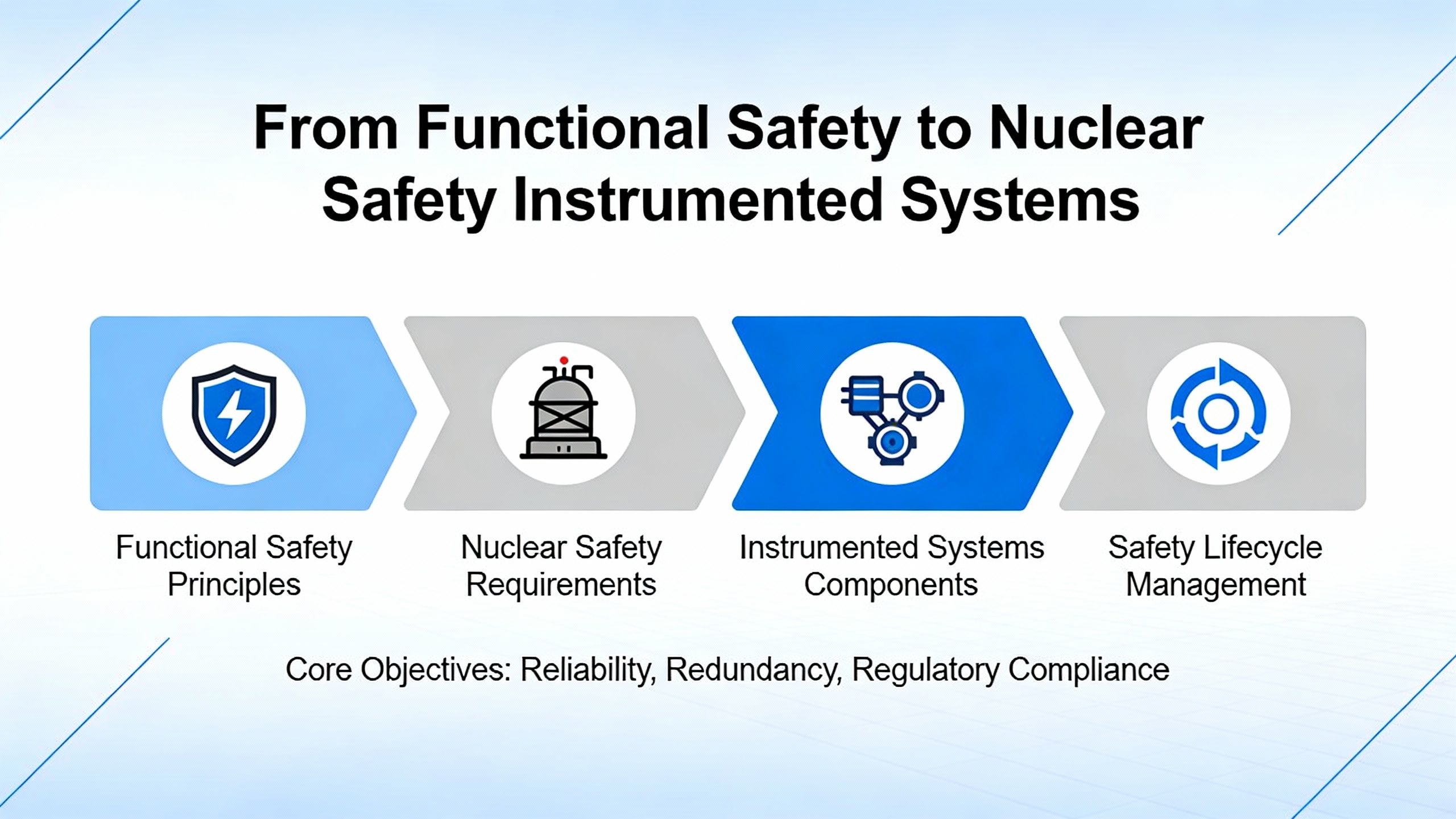
From Functional Safety to Nuclear Safety Instrumented Systems
Functional safety, as described by the UK Health and Safety Executive and by IEC 61508, is the part of overall plant safety that depends on automatic protection systems doing the right thing, at the right time, in response to defined hazardous conditions. In process and power industries, that functional safety is often implemented by Safety Instrumented Systems. These systems are not just ŌĆ£more control.ŌĆØ They are dedicated protection layers, separate from the Basic Process Control System, that monitor key variables and, on demand, drive the plant to a safe state.
Across sources such as Beamex, Zero Instrument, and functional safety guidance, the definition of a Safety Instrumented System is very consistent. An SIS is an engineered set of sensors, logic solvers, and final elements designed to implement one or more Safety Instrumented Functions. Sensors measure process parameters such as temperature, pressure, level, flow, or radiation dose. A logic solver, often a safetyŌĆæcertified programmable controller or other programmable electronic system, evaluates those signals against safety setpoints. Final elements, such as shutdown valves, motor starters, relays, or breaker trip coils, act on the process to bring it into a defined safe state. Supporting systems such as dedicated power supplies, instrument air, and critical communications are essential to this chain and must be designed with integrity levels that match the claimed safety performance.
In nuclear facilities, this architecture is tightly aligned with the nuclearŌĆæspecific standard IEC 61513 and with IAEA guidance on instrumentation and control systems for nuclear power plants. Those documents emphasize that safetyŌĆærelated I&C, including trip systems and engineered safety features actuation systems, must be functionally independent from systems used for normal control, provide clear humanŌĆōmachine interfaces for operators, and maintain their safety functions under both normal and accident conditions. A simple example illustrates the basics: if temperature in a safetyŌĆæcritical heat transfer loop exceeds a defined limit, an SIS can detect the excursion and automatically close a valve that isolates the heat source, bringing the process to a safe, nonŌĆæenergized state within a defined process safety time. In nuclear power, similar trip chains protect core cooling, reactivity control, containment isolation, and spent fuel cooling.
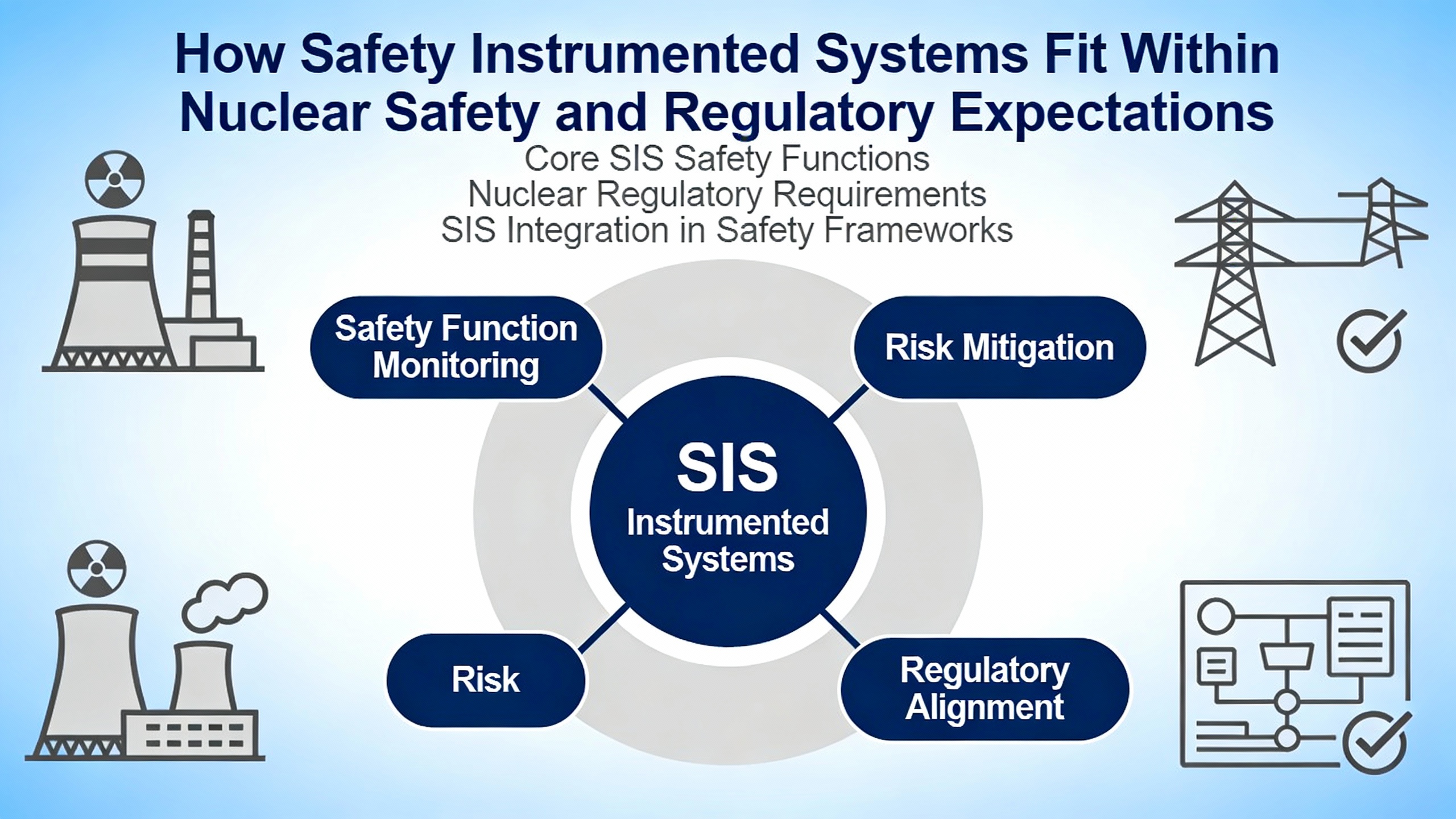
How SIS Fit Within Nuclear Safety and Regulatory Expectations
Regulators such as the US Nuclear Regulatory Commission and the Canadian Nuclear Safety Commission do not use the phrase ŌĆ£SILŌĆØ as often as processŌĆæindustry standards, but they absolutely specify the underlying expectations for reliability and independence of safety systems.
Appendix A to 10 CFR Part 50 in the United States sets general design criteria for reactor protection and engineered safety systems. Criteria on protection and reactivity control systems, fluid systems, containment, and power systems require that safetyŌĆæimportant structures, systems, and components be designed with high quality assurance, independence, and redundancy, and be capable of performing their safety functions even under natural hazards such as earthquakes and floods, as well as under postulated accidents such as loss of coolant events. The criteria also require onsite and offsite electric power systems that can each, assuming the other is unavailable, support safety functions.
Canadian regulatory document REGDOCŌĆæ2.5.2 takes a similar stance for new waterŌĆæcooled nuclear power plants. It requires multiple levels of defense in depth, clearly articulated safety goals, and design features that keep radiation doses during normal and abnormal events within strict limits aligned with IAEA and international radiological protection recommendations. It explicitly distinguishes between normal operation, anticipated operational occurrences, designŌĆæbasis accidents, and design extension conditions and requires that instrumentation and control systems support all of these states.
On the international side, IAEA safety guides on nuclear power plant I&C and on software dependability frame how SISŌĆælike functions should be designed, justified, and assessed when they rely on digital technologies. The IAEA dependability guidance stresses that software dependability encompasses safety, reliability, availability, maintainability, integrity, and security. It recommends building safety justifications using a structured claims, arguments, and evidence approach and using evidence from development artifacts, verification and validation, operational experience, and formal analyses.
When you map this regulatory landscape onto the SIS concept from IEC 61508 and IEC 61511, the message is clear. Nuclear protection systems are, in effect, highŌĆædemand, highŌĆæconsequence Safety Instrumented Systems governed by nuclearŌĆæspecific standards. They must demonstrate that they can meet stringent quantitative safety targets. World Nuclear Association summarizes current design trends by noting that the NRC requires a theoretical core damage frequency of not more than one in ten thousand reactorŌĆæyears, that US utilities aim for roughly one in one hundred thousand, that the best existing plants are around one in one million, and that some new designs are targeting about one in ten million. European regulators commonly require core damage frequencies no higher than one in one million for new builds. SIS design and SIL allocation are central tools for turning those numerical goals into engineered reality.
To see why, imagine that a particular nuclear hazard analysis identifies an initiating event with a frequency of about once in ten thousand reactorŌĆæyears and that, without an automatic shutdown, that event would lead directly to core damage. If your overall safety goal is to limit core damage to less than about one in one million reactorŌĆæyears, you need roughly a hundredŌĆæfold reduction in risk from protection systems and other measures. That places you in the range of a Safety Instrumented Function with SIL 2 performance, assuming other layers of protection, such as operator actions and physical barriers, are already accounted for. In practice, nuclear designers allocate risk reduction across multiple systems, but this simple illustration shows how SIL concepts can be aligned with nuclear design criteria.
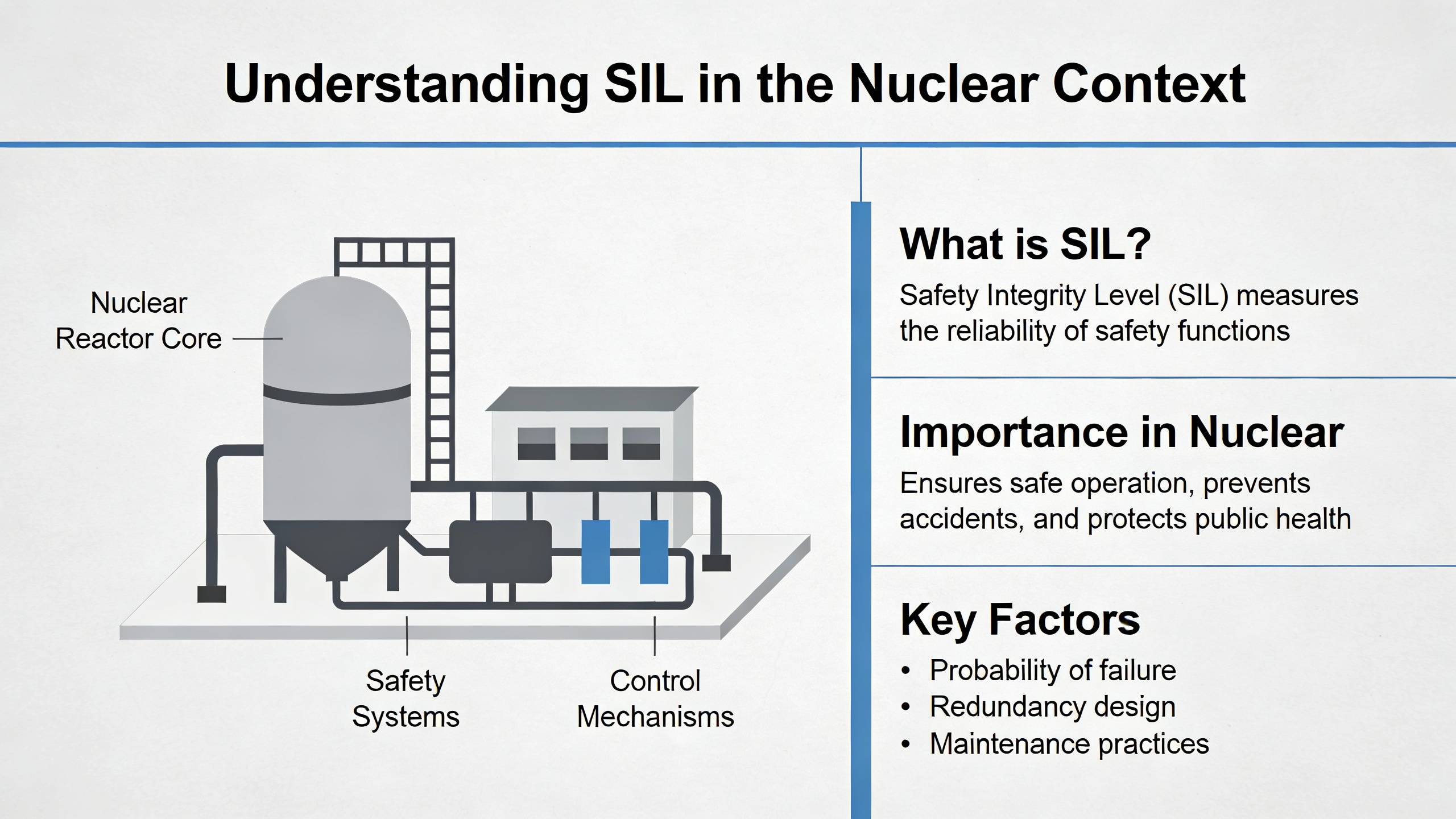
Understanding SIL in the Nuclear Context
Safety Integrity Level is a discrete measure of how reliably a given Safety Instrumented Function must perform. According to sources such as Beamex and Zero Instrument, SIL is defined in IEC 61508 and IEC 61511 for lowŌĆædemand functions in terms of average probability of failure on demand and the equivalent risk reduction factor. Beamex notes that SIL 1 corresponds to modest risk reduction, SIL 2 to significant risk reduction, SIL 3 to high risk reduction, and SIL 4 to extremely high risk reduction, typically reserved for the most critical functions, including many in nuclear and aerospace applications.
Zero Instrument provides typical numerical ranges for lowŌĆædemand Safety Instrumented Functions. Although exact ranges depend on the standard, one widely used set of values is reflected in the following table, along with approximate risk reduction factors.
| SIL level | Approximate risk reduction factor | Typical role in highŌĆæhazard applications |
| SIL 1 | About 10 to 100 | Adds a dedicated trip to supplement other protection layers for moderateŌĆæconsequence scenarios |
| SIL 2 | About 100 to 1,000 | Provides significant risk reduction for serious but localized hazards |
| SIL 3 | About 1,000 to 10,000 | Used for highŌĆæconsequence events where core or large equipment protection is at stake |
| SIL 4 | About 10,000 to 100,000 | Reserved for extremely highŌĆæconsequence scenarios, largely in nuclear and aerospace domains |
Each Safety Instrumented Function within an SIS is assigned a target SIL based on hazard analysis methods such as hazard and operability studies, quantitative process hazard analysis, and Layers of Protection Analysis, described in sources such as the Wikipedia article on SIS and the conceptual frameworks reviewed in academic work. In nuclear facilities, those studies must be aligned with regulatory probabilistic safety assessments, qualitative safety goals set by regulators, and the broader ŌĆ£Safety, Safeguards, and Security by DesignŌĆØ approach described by Sandia National Laboratories for advanced nuclear concepts.
Consider a simple numerical example using Zero InstrumentŌĆÖs risk reduction ranges. If a particular lossŌĆæofŌĆæcooling scenario has an estimated frequency of one in one thousand years at a given plant and the analysis shows that an automatic SISŌĆæinitiated actuation can reduce the frequency of core damage from this scenario by a factor of about one thousand, the resulting contribution from that scenario would be about one in one million years. That corresponds to a Safety Instrumented Function performing at approximately SIL 3. In practice, engineers refine these estimates using detailed failure rate data, redundancy modeling, and test interval assumptions, but the core logic remains the same: SIL defines how ŌĆ£tightŌĆØ the safety net must be.
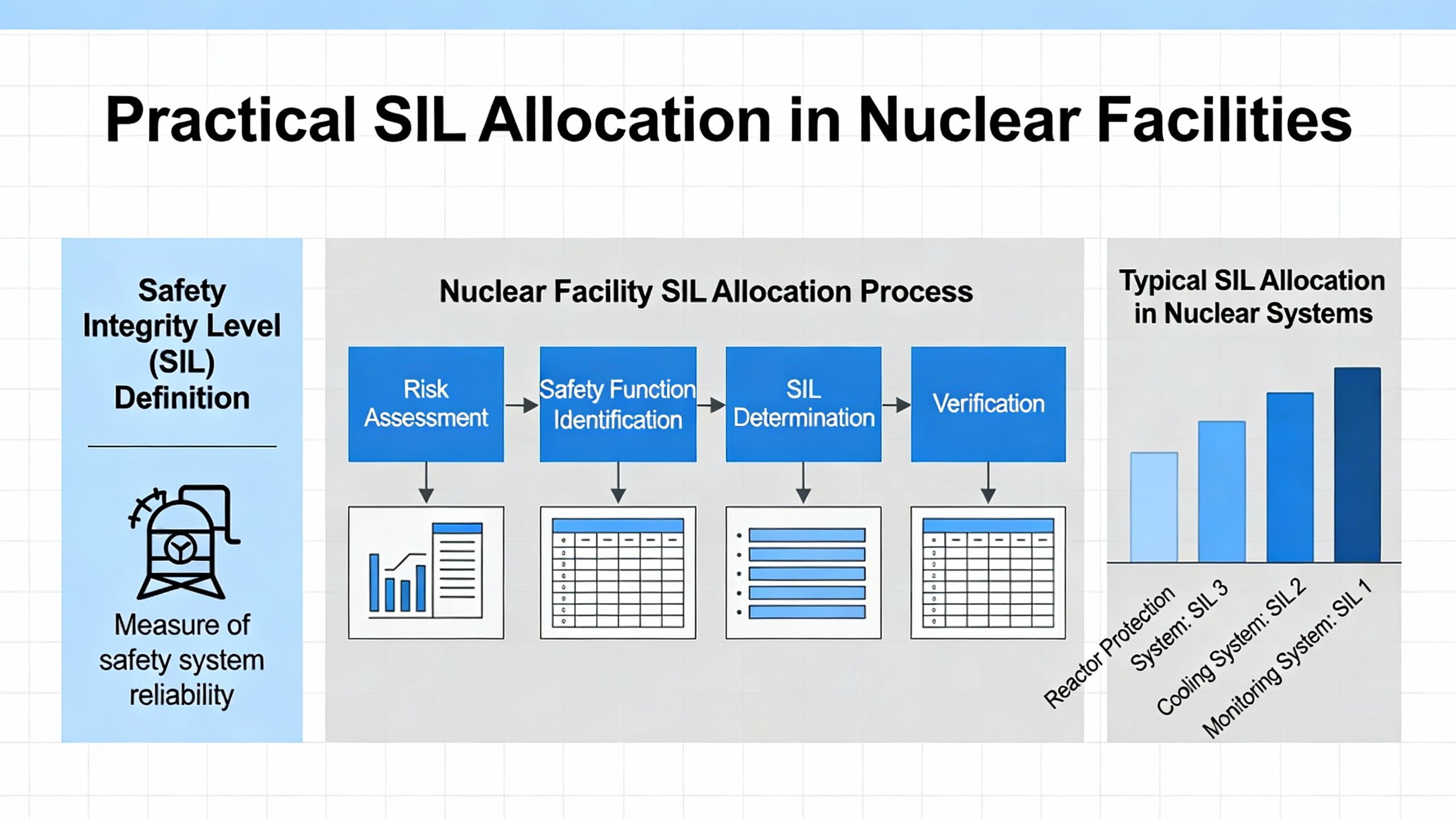
Practical SIL Allocation in Nuclear Facilities
Translating those SIL targets into plant design is where engineering judgment and standards meet.
Guidance from IEC 61511, as summarized by HSE and Method Functional Safety, and broader reviews in the SIS literature emphasize that SIL allocation begins with structured hazard and risk analysis. Methods such as hazard identification studies, frequency analysis, and Layers of Protection Analysis determine which scenarios require additional protection and what risk reduction is needed from each layer. Academic reviews note that these methods are as applicable to older nuclear plants and steam systems as they are to modern petrochemical facilities, especially when retrofitting protection onto legacy designs.
Once SIL targets are defined, engineers specify the corresponding Safety Instrumented Functions. Each SIF includes the process conditions that trigger it, the safe state to be achieved, and timing constraints such as the process safety time defined in SIS references. The architecture of sensors, logic, and final elements is then selected to meet the required SIL. Zero Instrument and Beamex both emphasize the role of hardware fault tolerance, diagnostics, and redundancy. For higher SILs, architectures such as ŌĆ£one out of twoŌĆØ or ŌĆ£two out of threeŌĆØ voting on sensors are common, combined with diagnostics and diversity to manage common cause failures.
Nuclear design standards overlay additional constraints on these choices. IAEA guidance on instrumentation and control stresses the need for independence between safety and nonŌĆæsafety systems, careful humanŌĆōmachine interface design, and consideration of accident and abnormal conditions. NRC general design criteria and CNSC design requirements impose expectations for quality assurance, documented design bases, and the ability to continue performing safety functions under fires, dynamic effects such as pipe whip, and natural hazards. An SIS architecture that meets an SIL target on paper but relies on a single, vulnerable power feed or on logic closely tied to the basic process control system would fall short of these nuclear expectations.
As a practical example, imagine a Safety Instrumented Function that initiates rapid shutdown and isolation in response to an abnormal reactivity signal. The hazard analysis may call for SIL 3 performance. To approach that level, designers could implement three diverse sensors feeding a dedicated safety logic solver, with final elements including shutdown rods, fastŌĆæacting valves, and power breakers, all arranged so that the system can tolerate one sensor failure without losing the safety function. That is a simplified concept, but it illustrates how SIL and nuclear redundancy principles point in the same direction.
Lifecycle: From Specification to Proof Testing and Software Dependability
A key message from both process industry standards and nuclear safety guidance is that SIL is not just a design label; it is a lifecycle commitment. The SIS safety lifecycle, described in IEC 61511 and summarized by HSE and Zero Instrument, covers everything from hazard analysis through specification, design, installation, operation, maintenance, modification, and decommissioning. NuclearŌĆæspecific guidance from IAEA and national regulators overlays additional expectations.
Defining the Safety Requirements
Method Functional Safety, which focuses on IEC 61511 Functional Safety Assessments, stresses that the first critical checkpoint, often called FSA 1, occurs once hazard and risk assessments are complete and the Safety Requirements Specification for the SIS is written but before detailed design begins. This assessment checks that hazard studies are adequate, that the SRS correctly captures required safety functions and SIL targets, and that all assumptions and data are documented for later verification. Typical findings in real projects include insufficient independent verification of hazard studies and gaps in SRS documentation that would make later validation difficult.
Although MethodŌĆÖs examples come from process industries, the principle maps directly to nuclear projects. Before committing to any reactor protection or engineered safety features actuation design, the combined team of nuclear safety analysts, I&C engineers, and power system specialists should be able to defend the hazard basis, the claimed risk reduction, and the selected SIL values. Given the complexity and long timescales of nuclear projects, the Method guidance to perform such assessments at the end of each lifecycle phase, rather than waiting for a final document, is particularly relevant.
Design and Verification of SIS Hardware and Software
The transition from specification to design, implementation, and verification is covered by a combination of functional safety standards and nuclear I&C guidance.
The IAEA Safety Guide on instrumentation and control for nuclear power plants emphasizes that digital technologies have transformed how safety systems are implemented. It addresses system architecture, design of control rooms and displays, human factors engineering, and cybersecurity for computerŌĆæbased systems. LongŌĆæterm issues such as ageing, obsolescence, and maintenance are identified as design considerations, not afterthoughts. It recommends lifecycle models that include systematic verification that systems meet safety requirements at each phase, from design and construction through commissioning and operation.
Complementing that, the IAEA publication on dependability assessment of software for safety instrumentation and control systems at nuclear plants provides a structured framework for demonstrating that the software side of a Safety Instrumented System is trustworthy. It defines software dependability in terms of safety, reliability, availability, maintainability, integrity, and security, and advocates a claims, arguments, and evidence approach. Evidence can include compliance with standards and codes, verification and validation results, modeling and analysis, inspections, reviews, and operational experience, as well as focused techniques such as functional validation, fault tree analysis, and even fault injection where appropriate.
WikipediaŌĆÖs overview of SIS points out that SIL requirements are verified across the lifecycle using design reviews, factory acceptance testing, site acceptance tests, and regular functional testing. When you combine that with nuclear expectations for independent verification and validation and for functional safety assessments at multiple stages, the outline of a rigorous SIS program emerges: specify, design, implement, and then assess using independent teams who can challenge assumptions and evidence.
A concrete example helps. Suppose a nuclear plant deploys a digital reactor protection system that implements several SIL 3 Safety Instrumented Functions. The dependability assessment would need to include evidence that the development process followed recognized standards, that the software implements the SRS correctly, that it behaves correctly under realistic and stressed conditions in factory and site tests, and that the underlying platform has been evaluated for common cause failures. In a claims, arguments, and evidence structure, the claim might be that the protection system fails to a safe state on any single internal fault. Arguments would reference architecture, defensive coding, watchdog mechanisms, and proof testing. Evidence would include design descriptions, test reports, and independent review findings.
Calibration, Proof Testing, and Functional Safety Assessment During Operation
Once an SIS is in service, the long, quiet years of operation can be both a blessing and a risk. The system is rarely demanded, but when it is, it must work.
Beamex emphasizes that calibration and proof testing are essential to maintain SIS reliability. Sensors and transmitters can drift, leading either to nuisance trips or, more dangerously, to missed trips. Final elements such as valves, actuators, and relays may stick or fail to move when required. Logic solvers must be checked to ensure that inputs are correctly translated into outputs according to the SRS. Proof testing strategies can be endŌĆætoŌĆæend, exercising the entire Safety Instrumented Function from sensor to final element, or componentŌĆælevel, where pieces are tested separately. Regardless of the approach, Beamex stresses that test coverage must address all parts of each SIF over time.
Importantly, there is no universal ŌĆ£annual calibrationŌĆØ rule. Beamex suggests that intervals should be riskŌĆæbased and tied to SIL targets, component failure rates, manufacturer guidance, and historical performance data. Typical intervals might be on the order of two to three years for SIL 1 devices, one to two years for SIL 2, and six to twelve months for SIL 3 loops, with SIL 3 emergency shutdown functions often proof tested as frequently as semiŌĆæannually. Any deviation from these intervals should be justified and documented based on data. Regulators, insurers, and thirdŌĆæparty certifiers such as T├£V or Exida are reported to scrutinize these programs, reviewing schedules, asŌĆæfound and asŌĆæleft data, proof test records, and management of change.
Operational experience from firms like Proconex reinforces the message that rigorous, ongoing SIS testing is not optional. They characterize relying on untested or faulty safety systems in highŌĆærisk facilities as an unacceptable risk, emphasizing the role of testing in providing assurance that SIS will work when demanded. For nuclear facilities, where even rare events can have significant consequences, these principles take on even more weight.
Functional Safety Assessment continues during operation as well. MethodŌĆÖs description of FSA 4 and FSA 5 offers a useful framework. FSA 4 is a periodic assessment during operations and maintenance, recommended soon after the first proof test cycle and then at intervals aligned with hazard study revalidation, often around every five years in process sectors. It checks whether operations and maintenance procedures are being followed, whether proof testing is effective, whether SIS performance data are collected and analyzed, and whether earlier assessment findings have been closed. A common issue noted is that technicians repair faults found during proof tests but do not record them as failures, depriving the organization of valuable nearŌĆæmiss data.
FSA 5 is triggered by modifications to the SIS. It assesses whether the modification plan is adequate for the risk, and whether implementation follows that plan. MethodŌĆÖs experience shows typical findings such as changes to safety logic that were not properly tested for unintended impacts elsewhere. Nuclear plants manage modifications under strict configuration control and management of change processes, but the functional safety lens adds further discipline: every change to a Safety Instrumented Function, including its supporting power supplies and communication paths, needs a structured assessment to confirm that SIL targets remain met.
To illustrate why these operational practices matter, consider a SIL 3 containment isolation function designed with a nominal probability of failure on demand consistent with a thousandŌĆæfold risk reduction. If proof testing intervals are doubled beyond what the risk analysis assumed, and if undetected failures are not rigorously recorded and analyzed, the real probability of failure could drift far above the target without anyone noticing until a demand occurs. That is why Beamex and others strongly recommend automated calibration management, highŌĆæaccuracy intrinsically safe calibrators, and investment in technician training.
Managing Modifications, Obsolescence, and Digitalization
IAEA I&C guidance and academic reviews of SIS implementation both stress the importance of planning for ageing, obsolescence, and the impact of digital technologies on safety and cybersecurity. As digital platforms age, components become unavailable, operating systems lose support, and cyber threats evolve. Replacing or upgrading a safety platform is not a simple likeŌĆæforŌĆælike swap; it is a modification to a Safety Instrumented System that can affect SIL claims.
Academic reviews highlight how emerging technologies such as intelligent sensors, Industry 4.0 connectivity, and IoTŌĆæbased monitoring platforms are changing both the design and the threat exposure of SIS. They emphasize that cybersecurity and data quality must be treated as core aspects of functional safety, not separate topics. For nuclear plants, IAEA safety standards and nuclear security series publications underline the need to integrate computer security into safety justifications.
In practice, this means that modifications and upgrades should be planned with FSA 5ŌĆæstyle assessments, updated hazard analyses, and refreshed dependability assessments. For example, if a plant decides to replace an aging safety PLC platform with a new digital platform that offers remote diagnostics over a network, the team must consider not only functional equivalence but also new failure modes and security vulnerabilities. Lessons learned from past digital I&C implementations, reflected in IAEAŌĆÖs dependability publication, show that common cause failures and platform certification issues can be significant if not carefully managed.
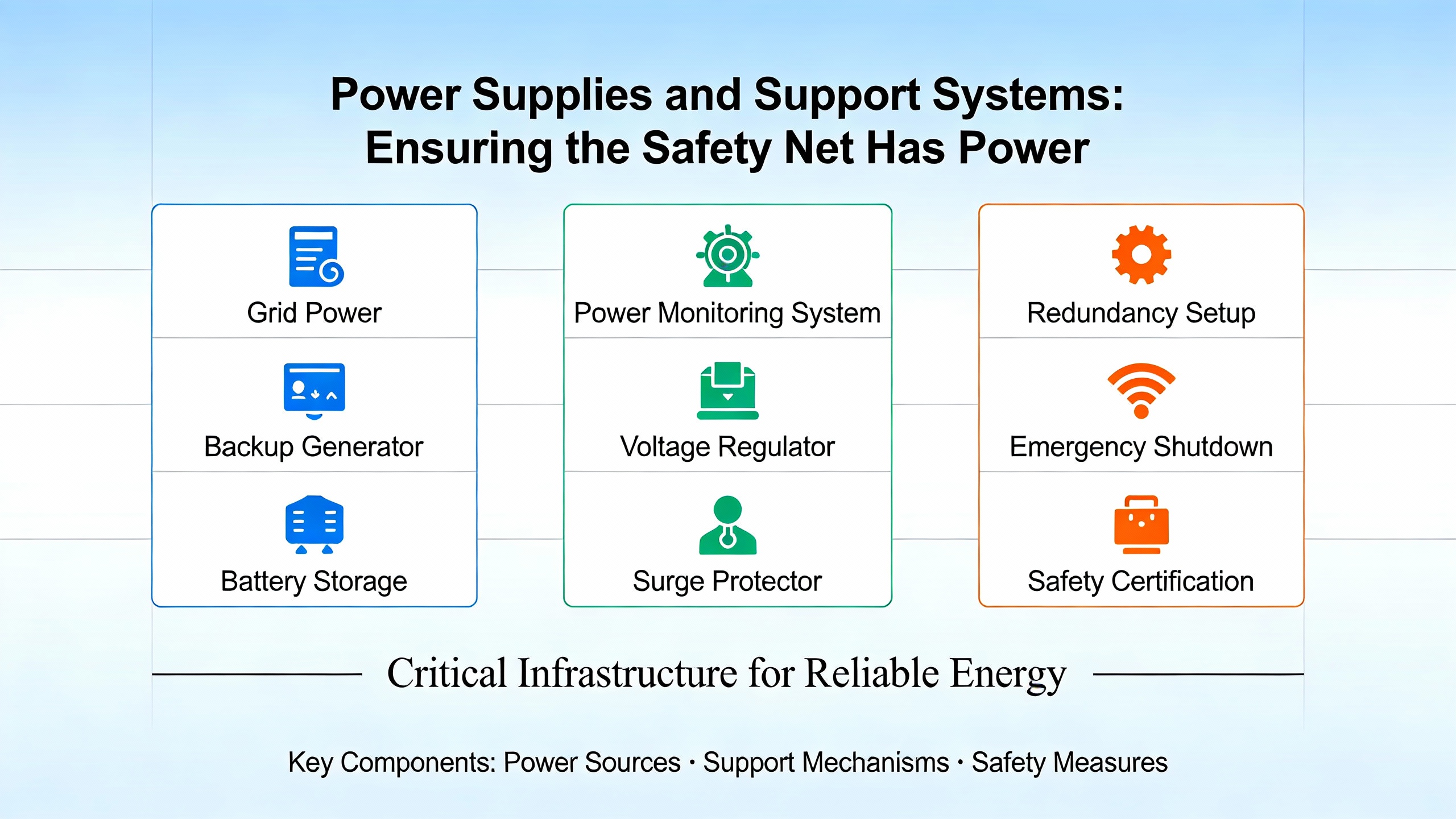
Power Supplies and Support Systems: Ensuring the Safety Net Has Power
Safety Instrumented Systems cannot perform if their support systems fail. WikipediaŌĆÖs description of SIS makes this explicit by noting that support systems such as power supplies, instrument air, and communications are necessary for SIS operation and must be designed with sufficient integrity and reliability to meet the required SIL. For nuclear facilities, that expectation ties directly into broader requirements on onsite and offsite power systems and on physical separation and protection of cables and equipment.
NRC general design criteria require that onsite and offsite electric power systems each be capable, on the assumption that the other is unavailable, of supporting safety functions. They also restrict sharing of safetyŌĆæimportant structures, systems, and components among multiple units to configurations that do not significantly impair safety. CNSC design guidance similarly demands that the design of structures, systems, and components, including power systems, support the safety objectives and levels of defense in depth.
From a power system specialistŌĆÖs perspective, this means that battery systems, inverters, uninterruptible power supplies, switchgear, and distribution feeders that support SIS must be treated as part of the safety function, not as generic utilities. Their reliability, maintainability, and fault tolerance must be consistent with the SIL targets of the Safety Instrumented Functions they support. They must also be protected against common cause failures such as fire, flooding, and seismic events, in line with criteria on environmental and dynamic effects in NRC and CNSC documents.
Consider a simple illustrative calculation. Suppose the logic solver and field devices in a particular Safety Instrumented Function are designed and maintained to achieve an average probability of failure on demand on the order of one in ten thousand. If the DC power supply feeding that logic has a failure probability on demand of one in one thousand, the combined probability of failure will be dominated by the power supply, and the overall function will fall short of SIL 3 performance. The exact numbers will vary by design, but the principle is always the same: supporting systems must be engineered so they do not become the weakest link.
In practice, designers can achieve this by providing redundant power sources for safety systems, by using power supplies and UPS systems with documented reliability and maintenance programs, and by ensuring physical and functional separation between safety and nonŌĆæsafety power feeds. Instrument air systems that drive safety valves must also be designed with reliability and redundancy consistent with SIL claims. IAEA I&C guidance reinforces that such dependencies must be analyzed and documented as part of the safety case.
For advanced nuclear concepts, Sandia National LaboratoriesŌĆÖ work on Safety, Safeguards, and Security by Design highlights the use of systemsŌĆælevel models to evaluate safeguards and security system designs, including for liquidŌĆæfueled reactors and bulk handling facilities. Their models integrate safety and physical security analysis and support evaluation of new approaches, including machine learningŌĆæbased safeguards. For power system specialists, this reinforces the need to think of SIS power and support systems not just as engineering details but as elements in a larger safety, safeguards, and security envelope.
Building a SILŌĆæRated Safety and Power Protection Strategy
When you put all pieces together, a coherent strategy for SILŌĆærated Safety Instrumented Systems in nuclear facilities emerges, grounded in standards and guidance rather than intuition.
First, treat SIS as independent, dedicated protection layers governed by functional safety standards and nuclear regulatory criteria, not as extensions of basic process control. Ensure that each Safety Instrumented Function is clearly defined, with a documented hazard basis, required risk reduction, SIL target, and process safety time.
Second, align SIS design with nuclearŌĆæspecific guidance such as IEC 61513, IAEA safety guides, NRC general design criteria, and national regulatory documents. That includes independence, diversity, redundancy, human factors, and environmental qualification, as well as strict quality assurance and documentation.
Third, build a lifecycle framework that covers hazard analysis, Safety Requirements Specification, design, implementation, verification and validation, calibration and proof testing, Functional Safety Assessment, and modification management. Use guidance from IEC 61511, HSE, Method Functional Safety, Beamex, and IAEA dependability frameworks to structure assessments and evidence.
Fourth, treat supporting systems such as power supplies, uninterruptible power supplies, inverters, instrument air, and critical communications as integral parts of the Safety Instrumented Functions. Their design, reliability, and maintenance programs must be consistent with the SIL claims and with nuclear design criteria on electric power systems and environmental and dynamic effects.
Finally, recognize that digitalization and new reactor concepts change both the opportunity and the risk landscape. Use tools and approaches highlighted by organizations like Sandia and Idaho National Laboratory to integrate safety, safeguards, and security by design, and ensure that software dependability and cybersecurity are embedded in your SIS strategy.
A wellŌĆædesigned, wellŌĆæmaintained SILŌĆærated Safety Instrumented System does more than satisfy regulators. It gives operators and power system teams confidence that, even on a bad day, the plant will behave predictably and safely. For nuclear facilities, that confidence, grounded in rigorous standards and disciplined engineering, is the real measure of success.
References
- https://www.hse.gov.uk/eci/functional.htm
- https://en.wikipedia.org/wiki/Safety_instrumented_system
- https://inl.gov/research-programs/nuclear-energy-safety-risk-assessment/
- https://energy.sandia.gov/programs/nuclear-energy/safety-security-and-safeguards-for-advanced-nuclear-power/
- https://www.standards.doe.gov/standards-documents/1100/1195-astd-2011/@@images/file
- https://www.energy.gov/sites/default/files/2023-06/LL%20of%20Integration%20Safety%20Design%20at%20DOE%20Nuclear%20Fac%20-%20June%202023.pdf
- https://www.nrc.gov/reading-rm/doc-collections/cfr/part050/part050-appa
- http://www.iaea.org/publications/10838/design-of-instrumentation-and-control-systems-for-nuclear-power-plants
- https://www.icheme.org/media/19418/hazards-29-paper-38.pdf
- https://ieeexplore.ieee.org/iel5/6413714/6445429/06445440.pdf


 Videos
 News
News Applications


Leave Your Comment