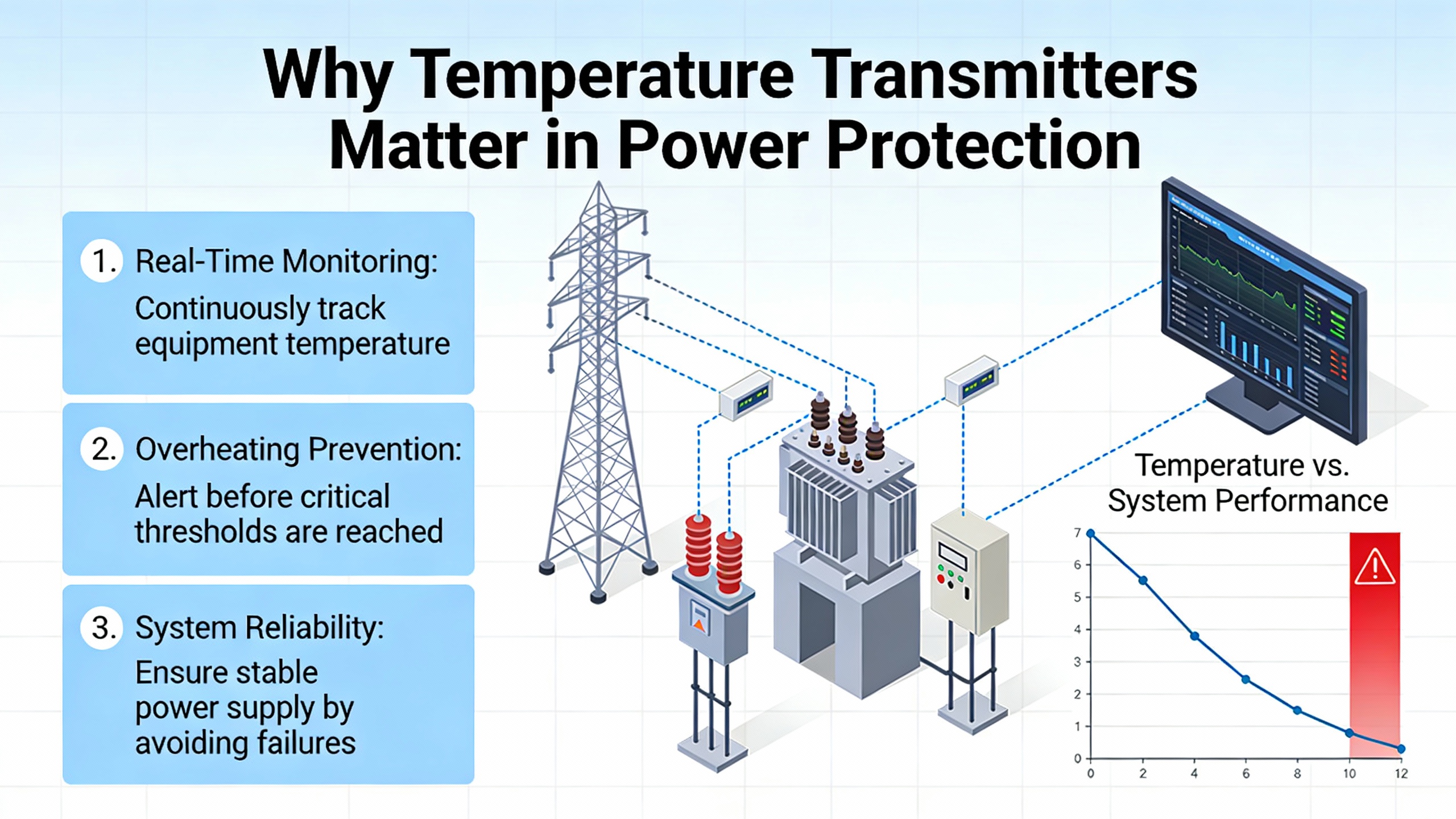
Why Temperature Transmitters Matter in Power Protection
In critical power systems, temperature is the quiet variable that often decides whether a UPS, inverter, or switchgear line-up runs for decades or fails on a hot afternoon in July. Power semiconductors in inverters, transformer windings in static switches, and even the batteries that live behind your UPS all share the same failure accelerator: elevated temperature.
Industrial instrumentation sources repeatedly point out that temperature is the most frequently measured physical parameter in industry. Tektronix notes that it underpins everything from materials research to electronics reliability, while Arrow Electronics emphasizes that thermal limits drive both mechanical stress and electronic drift in real equipment. For power protection systems, that reality is even sharper. Overheating IGBTs or transformers can trip protection, force load transfers, or, in the worst case, damage equipment that was supposed to protect the rest of the plant.
Temperature transmitters are the quiet translators in this story. They sit between harsh, analog sensing elements and the digital brains of your UPS controller, building management system, or SCADA platform. When they are specified well, you get stable readings, predictable alarms, and a clean integration path into your power protection strategy. When they are mismatched or misapplied, you get nuisance trips, undetected hot spots, and hours of forensic work.
This article focuses on Honeywell temperature transmitters, with a particular emphasis on the STT170 series, and uses independent guidance from Tektronix, Arrow Electronics, Czaki, and other instrumentation sources to explain which specifications and ranges actually matter for a power engineer or reliability advisor.
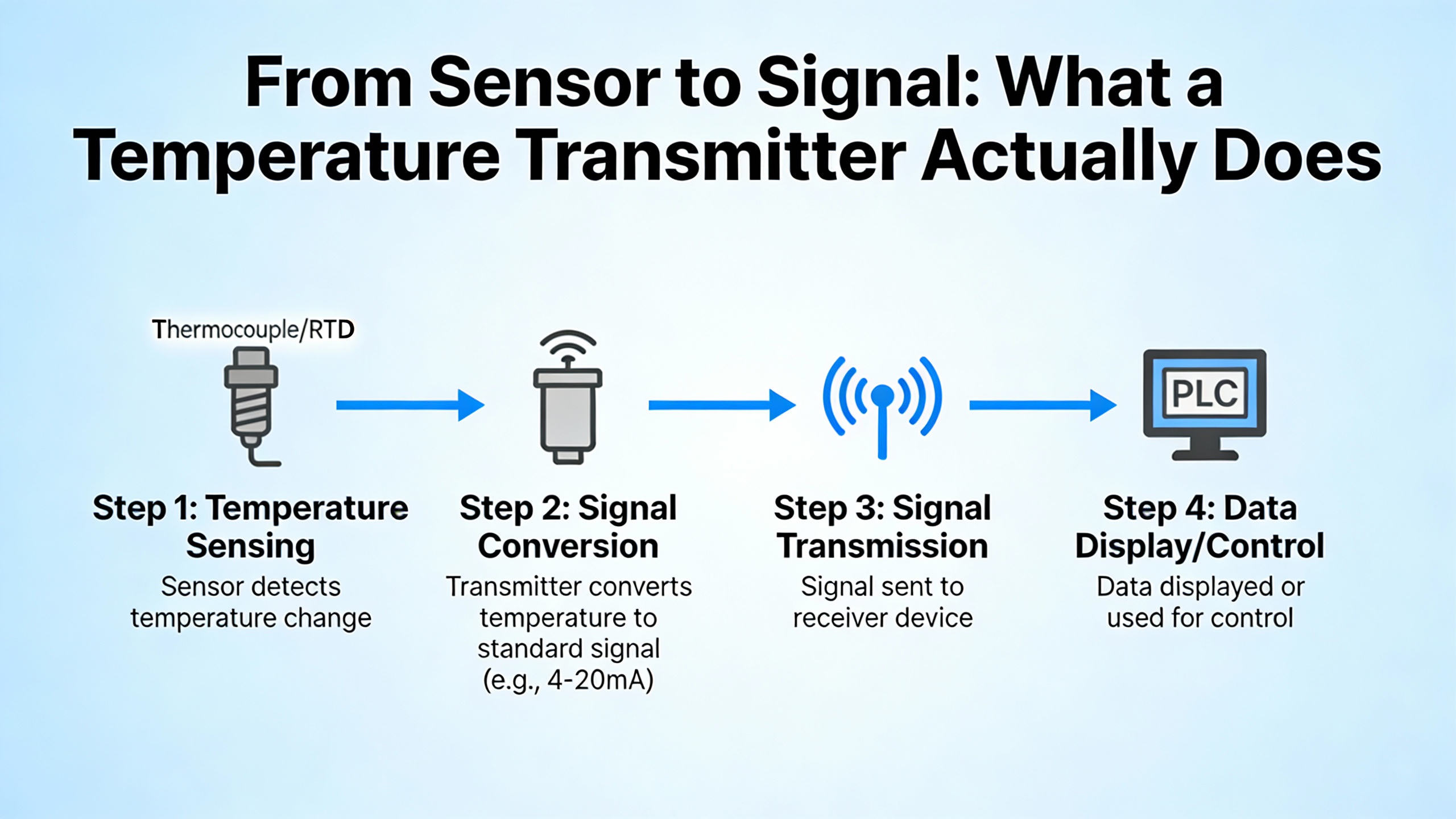
From Sensor to Signal: What a Temperature Transmitter Actually Does
A temperature transmitter does not measure temperature by itself. It conditions and converts the signal from a temperature sensor into something that a PLC, DCS, or intelligent UPS controller can understand reliably.
CzakiŌĆÖs transmitter selection guide defines the function very clearly: the transmitter takes a sensor input, such as a thermocouple or RTD, and converts it to a standard electrical signal like 4ŌĆō20 mA or 0ŌĆō10 V, or to a digital protocol such as MODBUS-RTU. That standardized signal can then travel long distances and be interpreted consistently by downstream systems.
Behind that simple description is a fair amount of physics and signal conditioning:
RTDs, or resistance temperature detectors, use a metal element whose resistance changes with temperature. Tektronix describes platinum RTDs as the accuracy and stability champions among common sensor types, capable in the best designs of spanning roughly from far below freezing up to well beyond red-hot metal temperatures, with excellent repeatability. They require a stable excitation current and careful handling of lead resistance, especially when you run the sensing element dozens of feet into a switchgear room.
Thermocouples, according to both Tektronix and Arrow Electronics, are the workhorses of industrial sensing. They rely on the Seebeck effect: two different metals joined at a junction produce a small voltage proportional to the temperature difference between the hot junction and a reference junction. They are rugged, inexpensive, and available in multiple types tuned for different temperature ranges, but they have modest accuracy and strongly non-linear behavior. As Tektronix notes, errors around one to three percent of reading are common in real installations, especially when cold-junction compensation is not handled well.
Thermistors are high-sensitivity, limited-range devices typically used where rapid response is more important than wide temperature coverage or extreme ruggedness. Arrow points out that negative temperature coefficient thermistors react very quickly to temperature changes, but they introduce complexity because their resistanceŌĆōtemperature curve is strongly exponential and must be linearized carefully.
The temperature transmitter sits on the other side of these sensors and performs several critical tasks:
It powers or biases the sensor (for RTDs and many thermistors), measures the raw resistance or microvolt-level signals, linearizes them according to the selected sensor curve, performs any needed cold-junction compensation for thermocouples, and maps the resulting temperature value into an output range such as 4ŌĆō20 mA. In a simple conceptual example, if you configure a transmitter to represent 32┬░F with 4 mA and 212┬░F with 20 mA, the span is 180┬░F across 16 mA of current. That means each degree corresponds to roughly 0.09 mA. Your PLC or UPS controller reverses that mapping to recover the temperature, and its alarm setpoints rest entirely on the transmitter doing that job correctly and consistently.
In a UPS room, that might translate to putting RTDs on transformer windings inside static transfer switches and thermocouples on inverter heat sinks, then feeding all of those into transmitters that send scaled 4ŌĆō20 mA signals to a centralized controller. The quality of those transmitters directly influences how confidently you can run equipment near nameplate thermal limits.
Honeywell STT170 Series: What the Brochure Actually Tells Us
HoneywellŌĆÖs STT170 series is presented in its brochure as a cost-effective, smart 4ŌĆō20 mA temperature transmitter line aimed at basic temperature monitoring and OEM applications. It is explicitly targeted at industries like cement, sugar, food and beverage, and inorganic chemicals, as well as OEM equipment such as curing presses, compressors, metering skids, furnaces, and ovens. Those are harsh, thermally demanding environments that have a lot in common with power electronics rooms and distribution gear: vibration, electrical noise, and elevated temperatures near live equipment.
Several technical themes stand out in the Honeywell STT170 material and are especially relevant to UPS and power protection applications.
Input Types and Sensor Flexibility
The STT170 family is described as universally programmable, model-dependent, for RTD, thermocouple, Ohm, or millivolt inputs. That universal input concept matters in a power system because you often face a mixed sensor population:
You might inherit existing Pt100 RTDs embedded in transformer windings or bus ducts, thermocouples welded to inverter heat sinks, and perhaps some OEM-specific sensing elements feeding millivolt outputs from packaged drives or rectifiers. A transmitter family that can be configured for multiple sensor technologies reduces the number of part numbers you must manage and simplifies spares.
One STT170 variant, the STT171, is called out as a 4ŌĆō20 mA model for RTD and Ohm inputs with NAMUR NE43-compliant fault behavior. Another, the STT173, expands inputs to RTD, thermocouple, Ohm, and millivolt signals and adds galvanic isolation. Companion smart models, STT17H and STT17F, are highlighted as supporting single or dual sensors, including difference, average, or redundant configurations.
Those dual-sensor strategies are particularly valuable around critical power components. For example, you might put two RTDs on opposite sides of a UPS transformer core and configure a dual-input Honeywell transmitter to compute the average temperature for steady-state control while also monitoring the difference between sensors. A rising difference might indicate a localized hot spot, winding defect, or cooling issue even before the absolute temperature crosses an alarm threshold.
Independent guidance from Tektronix and Arrow reinforces the importance of matching sensor type to task. Thermocouples handle very wide and high temperature ranges and are mechanically robust, which suits them for mounting directly on hot bus bars or furnace-like environments. RTDs, with better stability and accuracy, are often preferable for transformer and heat sink monitoring where you want precise control near a defined operating ceiling. A universal-input transmitter like the STT170 series gives you the flexibility to use the sensor that makes sense for each location without redesigning your signal chain.
Outputs, Protocols, and Control Integration
On the output side, the STT170 family covers the main integration patterns you see in power systems:
The STT171 and STT173 models provide a conventional 4ŌĆō20 mA analog output. That is still the dominant signal format for simple temperature loops in switchgear and UPS systems. The loop can be powered from a control cabinet, run through existing terminal blocks, and land on either a PLC analog input card or a controller inside a UPS frame.
The STT17H model combines 4ŌĆō20 mA with HART digital communication and supports multidrop operation. In a HART multidrop configuration, you can have multiple transmitters on a single pair of wires, each sharing the same fixed loop current while a host system communicates digitally with each device. That is attractive when you want to instrument many temperature points along a long bus duct or in a battery room without pulling separate cables back to a central rack.
The STT17F model supports FOUNDATION fieldbus and is described as providing two analog function blocks and one PID block. That means it can participate directly in a digital process network and even run a local control loop. In power protection context, imagine a fieldbus segment that includes both a temperature transmitter and a small trim heater for a critical outdoor UPS enclosure. A local PID block inside the transmitter could regulate enclosure temperature directly, while the higher-level system focuses on alarms and logging.
HoneywellŌĆÖs brochure states that the STT17F model also includes FDT-certified Device Type Managers, which simplifies integration with multi-vendor asset management tools. In practice, that means your maintenance software can recognize the device, expose its parameters, and assist with configuration without you writing custom drivers.
CzakiŌĆÖs discussion of transmitter selection stresses that matching output type and communication protocol to your plant architecture is a core decision. Analog outputs match legacy systems with minimal changes, while digital protocols like MODBUS-RTU, HART, and fieldbus variants unlock richer diagnostics, multi-drop wiring savings, and more flexible configuration. HoneywellŌĆÖs STT170 range lines up with that pattern, giving you a choice between simple loops and smarter, bus-based designs.
Isolation, Diagnostics, and Safety Behavior
In power rooms, galvanic isolation is not a luxury; it is a reliability control. High fault currents, long ground paths, and mixed earthing schemes create ample opportunity for ground loops and noise. Czaki explicitly recommends galvanic isolation between input, power, and communication interfaces where installations are electrically noisy or safety-critical.
The STT170 brochure highlights that models such as STT173, STT17H, and STT17F provide electrical galvanic isolation. That isolation helps break ground loops and prevent noise on the high-energy side from corrupting low-level sensor readings or damaging control electronics. In a 480 V switchgear lineup with multiple UPS modules and static transfer switches, locating isolated transmitters at the field device and running clean 4ŌĆō20 mA or digital signals back to the control system is a practical way to contain noise.
Honeywell also emphasizes diagnostic and safety features, including high- and low-limit alarms and NAMUR NE43-compliant sensor error response. NAMUR NE43 is a widely accepted standard defining how transmitters should drive their 4ŌĆō20 mA output under fault conditions. Instead of drifting to arbitrary values, the loop current is driven into clearly defined under-range or over-range bands outside the normal operating span. In a power system, that predictability matters. Your PLC or UPS controller can treat those bands as ŌĆ£definite sensor failure,ŌĆØ trigger a redundant sensor input if available, and, if necessary, initiate a controlled transfer or load shedding sequence.
The STT17FŌĆÖs FISCO certification is noteworthy for hazardous-area fieldbus applications. While many UPS and battery rooms are not classified as hazardous locations, some plants do route power equipment into classified zones. In those cases, an intrinsically safe fieldbus segment with certified devices can be an enabling technology.
A very practical example: imagine RTDs on a transformer bank feeding a critical UPS. Without isolation, noise introduced by fault currents or parallel cable routes can shift the apparent resistance, causing subtle temperature reading errors. Even a small error could mean the difference between operating comfortably below your thermal limit and creeping into an unmonitored over-stress situation. An isolated transmitter, by contrast, breaks the direct electrical path and reduces those errors significantly, especially when combined with proper shielding and grounding practices.
Mechanical Form Factor and Installation Options
Honeywell describes the STT170 series as ultra-compact, designed to fit into small DIN B head-mount housings. That head-mount capability means you can install the transmitter inside the temperature sensor head near the actual measurement point, minimizing the length of low-level sensor wiring. From a noise and reliability perspective, that is a win in any power equipment room with strong electromagnetic fields.
The brochure also notes that optional field-mount housings are available, including versions with a local meter that displays measurements in engineering units. That local indication is more than a convenience. In a large UPS room, technicians can quickly verify temperatures at the equipment itself without walking back to the control room, which significantly speeds troubleshooting during abnormal events.
This mechanical flexibility matches what Czaki describes across its own product range: a split between DIN rail-mounted transmitters in panels and head-mount transmitters integrated directly with the sensor assembly. For many power applications, a head-mounted Honeywell STT170 on critical components (transformer tops, bus ducts, inverter sinks) plus a few panel-mounted transmitters for room ambient sensors creates a solid, maintainable architecture.
STT170 Model Overview
The brochure excerpt provides enough detail to distinguish the main STT170 variants at a functional level. The table below summarizes those distinctions, staying strictly within what is documented:
| Model | Output / Protocol | Inputs (per excerpt) | Isolation | Notable features / positioning |
| STT171 | 4ŌĆō20 mA | RTD / Ohm | Not specified | Cost-effective analog model with NAMUR NE43-compliant fault response |
| STT173 | 4ŌĆō20 mA | RTD / T/C / Ohm / mV | Galvanic isolation | Universal analog transmitter with isolation for noisy or safety-critical loops |
| STT17H | 4ŌĆō20 mA with HART | Single or dual sensors (types not detailed in excerpt) | Galvanic isolation | HART smart transmitter with multidrop capability and dual-sensor strategies |
| STT17F | FOUNDATION fieldbus | Single or dual sensors (types not detailed in excerpt) | Galvanic isolation | Fieldbus model with two analog function blocks, one PID block, and FISCO cert. |
The family shares several cross-cutting traits: compact form factor, optional local display via field housings, configuration via the STT17C PC-based configuration tool for applicable models, and a design emphasis on good price-performance for industries that demand reliability without premium pricing.
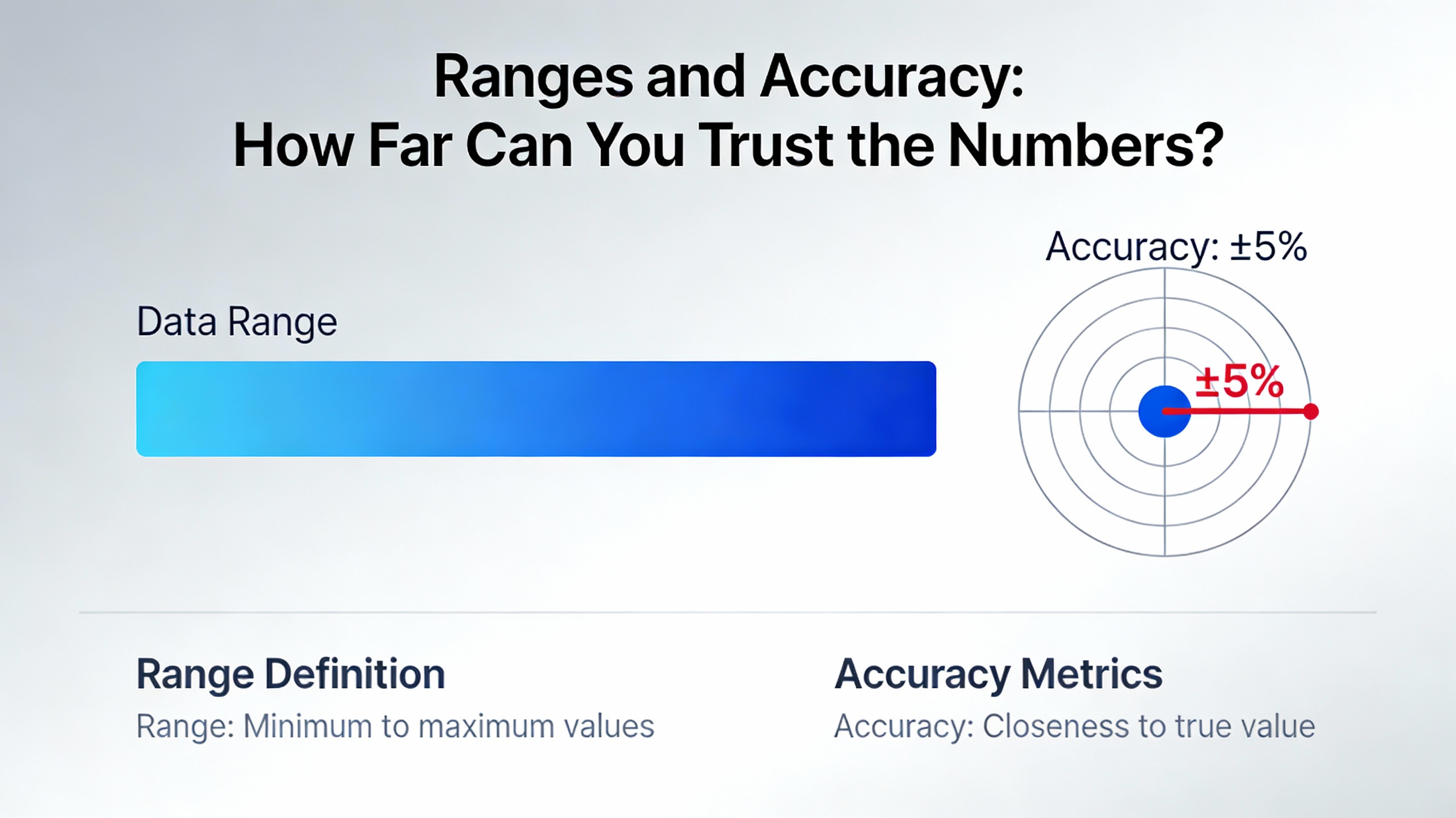
Ranges and Accuracy: How Far Can You Trust the Numbers?
The available Honeywell brochure excerpt does not list explicit numerical temperature ranges or accuracy figures for the STT170 models. That is an important limitation to acknowledge. For design work in a critical power system, you will need the full model datasheets to see exact limits and tolerances.
However, the independent sources summarized in the research provide useful context about what ranges and accuracies are typical for the sensor technologies that Honeywell supports.
Tektronix explains that thermocouples cover very wide temperature spans, including both extremely low cryogenic levels and the high temperatures seen in kilns, furnaces, and engine components. Accuracy for practical industrial thermocouple systems typically lands in the one to three percent band, with significant contributions from alloy variability and cold-junction compensation errors. That means that at a true temperature around 600┬░F, total system error might be on the order of a few tens of degrees Fahrenheit if the system is not carefully designed and calibrated.
RTDs, in contrast, are described as offering the best stability and accuracy across the commonly used sensor families. In well-designed systems, they support accurate measurements across a very broad range that spans from deep cryogenic conditions at one end to glowing metal temperatures at the other, with significantly tighter tolerances than thermocouples. The trade-offs are higher sensor cost, the need for a stable excitation current, and sensitivity to self-heating and lead resistance errors.
Thermistors, as Arrow emphasizes, exhibit very high sensitivity and very fast response, especially useful where temperature swings quickly and you care about the rate of change. But their usable range is more limited and they are less rugged than thermocouples and RTDs, which makes them less common directly in the highest stress portions of power equipment.
Since the STT170 series is designed to accept RTD, thermocouple, Ohm, and millivolt inputs (with specific combinations depending on the model), you configure its measurement range to match both the chosen sensor and the expected process temperatures. In a power system, that may involve:
Defining a range that comfortably covers the expected transformer top-oil temperature envelope with margin for abnormal events, selecting an RTD type and class that provides the desired accuracy in that span, then configuring the transmitterŌĆÖs lower and upper range values accordingly.
Choosing thermocouples for particularly hot elements, such as bus connections or furnace power feeds, then pairing them with STT173 or smart STT17H/STT17F models while being realistic about the one to three percent measurement uncertainty typical of thermocouple systems.
The key is that the transmitterŌĆÖs own specified input limits and output mapping must fully include the temperatures you expect to see, and its accuracy (combining sensor and electronics) must be adequate for your control and protection strategy. Because the partial Honeywell brochure does not include those numeric limits, your workflow should explicitly include pulling the model-specific datasheet, checking the supported sensor ranges, and comparing them against the worst-case thermal scenarios for your UPS, inverter, and distribution equipment.
A simple conceptual example illustrates why this matters. Imagine you want to keep a transformer winding below a certain threshold. If your selected sensor and transmitter combination has a total uncertainty of five percent over the relevant range, and your allowed operating window is only ten percent wide, you have very little safety margin. By switching to a higher-accuracy RTD with a carefully configured STT173, and by minimizing wiring errors and noise, you could shrink that uncertainty and allow your equipment to operate closer to its design limit without eroding safety.
Matching Honeywell Specifications to Power System Requirements
Putting the pieces together, the question for a power engineer is not simply ŌĆ£Which Honeywell transmitter is best?ŌĆØ but ŌĆ£Which specifications align with the risks and integration constraints of this particular UPS or power distribution project?ŌĆØ The research from Czaki and the general sensor-selection guidance from Tektronix and Arrow point to a structured way to think about that decision.
First, clarify what you are actually measuring. Transformer windings, inverter heat sinks, cable terminations, bus ducts, battery strings, and room ambient can all require different sensor types and mechanical attachments. RTDs are a strong fit for windings and heat sinks where accuracy and drift stability are important. Thermocouples are robust for welded junctions on hot conductors. If your plant has a mixture, then a universal-input transmitter like the Honeywell STT173 or a dual-sensor smart model can reduce complexity.
Second, decide where the transmitter belongs physically. Head-mount STT170 units installed directly at the sensor reduce low-level wiring runs and improve noise immunity. Panel or field-mount housings, especially with local displays, improve accessibility for maintenance and commissioning. CzakiŌĆÖs comparison of DIN rail and head-mount transmitters mirrors this trade-off across the broader market.
Third, align the output protocol with your control architecture. If your UPS and switchgear protection are built around an existing PLC with spare analog current inputs, an analog STT171 or STT173 might be simplest. If you are consolidating many measurement points along a single cable run in a bus duct or battery rack, a HART-based STT17H with multidrop capability offers wiring savings and richer diagnostics. If your plant uses FOUNDATION fieldbus for process instrumentation, the STT17F allows you to keep temperature monitoring on the same digital backbone, leveraging its analog function blocks and PID for local control where appropriate.
Fourth, assess the need for galvanic isolation and advanced diagnostics. In a quiet, small UPS installation, a non-isolated transmitter might be acceptable. In a large, multi-source switchgear room with dozens of high-current feeders, isolated Honeywell models such as the STT173, STT17H, and STT17F give you significantly better resilience against ground loops and surge-induced disturbances. NAMUR NE43 behavior, high/low limit alarms, and, in the case of STT17F, richer diagnostics through fieldbus and FDT-based tools, all help your operations team distinguish between genuine thermal events and sensor or wiring faults.
Finally, cross-check all of these choices against the actual ranges and accuracy requirements of your application. The independent sensor-selection references highlight the interplay between environment, required range, needed accuracy, acceptable response time, and cost. For example, Tektronix notes that deploying a thermocouple in a high-temperature, high-noise environment without adequate amplification and linearization can yield large tolerances that may be unacceptable for tight control. In that case, pairing a carefully chosen RTD with an appropriate Honeywell STT170 model may yield better control even if the sensor itself is more expensive.
Common Pitfalls in Specifying Temperature Transmitters for UPS and Inverter Systems
Several recurring pitfalls show up in real installations and are echoed in the independent guidance from Tektronix, Arrow, and Czaki. Framing them explicitly can help you use Honeywell transmitters more effectively.
A frequent issue is treating the temperature transmitter as an afterthought, specified late and simply ŌĆ£made to fitŌĆØ whatever sensors happen to be in stock. Czaki warns against this, emphasizing that transmitter selection should be driven by sensor type, wire configuration, output requirements, mounting style, communication interface, and galvanic isolation needs. In a sensitive power room, failing to specify isolation or choosing a model that does not support the correct RTD wire configuration can inject avoidable error and noise into your control system.
Another pitfall is ignoring lead resistance and wiring practices for RTDs. Tektronix explains that two-wire RTD connections fold lead resistance directly into the measurement, which can introduce sizable errors over long cable runs. Three-wire and four-wire configurations progressively compensate for that effect. If you install a high-accuracy RTD on a UPS transformer and then wire it back to a head-mount Honeywell STT171 in a way that does not match the transmitterŌĆÖs configured wire mode, you throw away much of the sensorŌĆÖs inherent performance. Matching the transmitter configuration to the physical wiring, and limiting lead length where possible, is essential.
Thermocouple installations often suffer from poor cold-junction compensation and unrecognized additional junctions. Tektronix details how using the wrong extension wire materials or allowing additional junctions to form at terminal blocks introduces spurious voltages that the transmitter will interpret as temperature. Even though the Honeywell STT173 and its smart counterparts provide the necessary linearization and compensation functions internally, they cannot correct for wiring mistakes upstream. In a switchgear environment where thermocouples might be routed through crowded terminal compartments, disciplined use of proper extension cable and attention to polarity is critical.
Self-heating in RTDs and thermistors is another subtle source of error. Tektronix notes that raising the excitation current increases power dissipated in the sensor, which in turn raises its temperature above the actual process value. The relationship between self-heating and applied power is straightforward: if you double the excitation current, the dissipated power rises by a factor of four. Modern transmitters are generally designed with suitable excitation currents, but if you daisy-chain sensors, deviate from recommended wiring, or choose non-standard elements, you can inadvertently increase self-heating errors.
Finally, many sites fail to use the diagnostic capabilities that smart transmitters provide. HoneywellŌĆÖs STT17H and STT17F models, combined with PC-based configuration tools and asset management software, expose device status, configuration, and fault conditions that can be invaluable during commissioning and troubleshooting. Czaki emphasizes similar benefits for its own digital transmitters with MODBUS-RTU. In a UPS or inverter installation, enabling and actually monitoring these diagnostics can quickly separate a failing sensor, a wiring short, or a transmitter configuration issue from a genuine thermal overload event.
A practical way to avoid these pitfalls is to treat the temperature loop as a complete chain during design reviews. Sensor selection, mechanical mounting, wiring approach, Honeywell transmitter model and configuration, and receiving controller scaling all need to be considered together. Walking through one or two example points end-to-end, including how faults will appear in the control system, is often enough to catch misalignments before they reach the field.
Short FAQ
Q: Do Honeywell STT170 transmitters cover the full range of my RTD or thermocouple sensors? The available brochure excerpt confirms that the STT170 family is universally programmable, model-dependent, for RTD, thermocouple, Ohm, and millivolt inputs, but it does not list explicit numerical temperature limits. Sensor technologies such as thermocouples and RTDs are capable of very wide ranges according to Tektronix and Arrow, yet individual transmitters sometimes restrict the usable span for accuracy or safety reasons. For a UPS or inverter design, you should always consult the detailed Honeywell datasheet for the specific STT170 model and sensor type you intend to use, then verify that the configured range fully covers your expected operating and alarm temperatures with adequate margin.
Q: When does it make sense to choose STT17H or STT17F instead of STT171 or STT173? STT171 and STT173 are analog 4ŌĆō20 mA devices, which integrate easily with existing control panels and UPS controllers that already have analog input cards. STT17H and STT17F are smart devices: STT17H adds HART over 4ŌĆō20 mA with multidrop capability, and STT17F connects directly to FOUNDATION fieldbus and includes function blocks, including a PID block. If your power system already uses digital networks, needs richer diagnostics, or can benefit from multi-drop cabling to reduce wiring in large equipment rooms, the smart models are typically the better fit. If you are retrofitting a small number of points into an analog-only system, the analog models may be simpler and more cost-effective.
Q: How important is galvanic isolation for temperature transmitters in power rooms? Both CzakiŌĆÖs guide and HoneywellŌĆÖs STT170 brochure underscore the value of galvanic isolation in noisy or safety-critical installations. In UPS rooms, inverter galleries, and large switchgear line-ups, isolation reduces ground-loop errors and protects the control system from transients originating near high-energy conductors. Honeywell explicitly notes that STT173, STT17H, and STT17F include galvanic isolation, making them strong candidates when sensor wiring shares routes with high-voltage cabling or when you are bridging different grounding domains.
Closing Perspective
In modern UPS and power protection architectures, temperature transmitters are small components with outsized influence on risk. HoneywellŌĆÖs STT170 series, as described in the brochure, provides a practical set of options: universal inputs, compact head-mount form factors, analog and smart communication choices, galvanic isolation on key models, and diagnostics aligned with industry standards like NAMUR NE43 and FISCO. When you pair those capabilities with careful sensor selection and disciplined wiring, following the independent guidance from Tektronix, Arrow, and Czaki, you get temperature data you can trust and thermal limits you can enforce confidently. In critical power systems, that combination is one of the most cost-effective reliability upgrades you can make.

References
- https://controltrends.org/wp-content/uploads/2011/11/Honeywell-STD.pdf
- https://www.arcweb.com/technology-evaluation-and-selection/temperature-transmitters-selection
- https://zeroinstrument.com/selecting-a-temperature-transmitter-a-comprehensive-guide/
- https://www.czaki.pl/en/how-to-choose-the-right-temperature-transmitter/?srsltid=AfmBOopnY8AeXGg6z7g4Y8soQn8_TslPOLdsXFPGbIah0__wQhkC-t5X
- https://www.emerson.com/documents/automation/-engineer%E2%80%99s-guide-to-industrial-temperature-measurement-en-5431280.pdf
- https://www.scribd.com/document/731759264/Honeywell-Temperature-brochure
- https://www.arrow.com/en/research-and-events/articles/industrial-temperature-sensor-types-and-how-they-work
- https://cbprocess.ca/products/field-instruments/temperature/
- https://www.miinet.com/images/pdf/articles/IPPT-2019-10-Oct-Temp-and-Safety-temp.pdf
- https://www.tek.com/en/documents/technical-article/how-select-right-temperature-sensor


 Videos
 News
News Applications


Leave Your Comment