In industrial and commercial power supply systems, the SIMATIC S7-1200 usually ends up as the ŌĆ£brainŌĆØ behind UPS transfer schemes, inverter controls, and power protection interlocks. In that role, wiring quality matters just as much as the logic in your program. A clean, standards-based wiring diagram is what stands between a reliable, maintainable control panel and a rack full of intermittent faults that show up only when the UPS is on battery or the inverter is ramping.
Drawing and implementing that wiring diagram correctly is not about artistic detail; it is about routing power, signals, and communication in a way that respects SiemensŌĆÖ S7-1200 wiring guidance, good electrical practice, and the realities of noisy power rooms. This guide focuses on the connections and installation details that most directly affect safety and reliability, based on Siemens S7-1200 manuals, industrial wiring guides, and real-world issues reported on Siemens and automation forums.
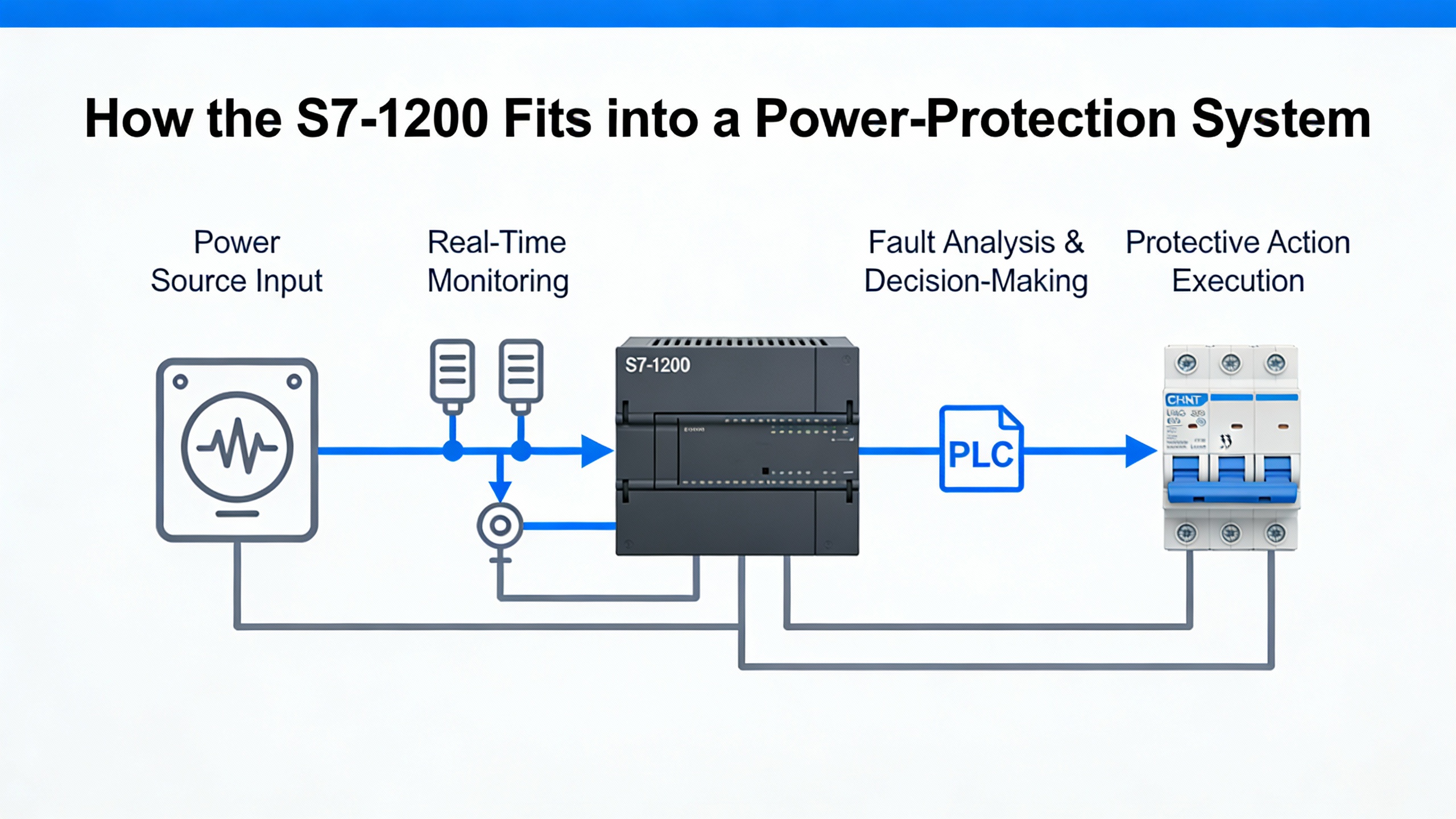
How the S7-1200 Fits into a Power-Protection System
Before you worry about symbols and terminal numbers, you need to be clear about what the S7-1200 is doing in your power system.
A programmable logic controller is an industrial computer that monitors inputs, executes a stored program, and controls outputs to automate machines or processes. In a typical power-protection panel, the S7-1200 receives signals from breakers, contactors, UPS status contacts, temperature and current transmitters, and it drives relays, indicator lights, buzzer alarms, and sometimes communication links to supervisory systems. Siemens training materials describe the basic PLC structure as inputs, a CPU, and outputs, with the CPU repeatedly scanning inputs, executing logic, and updating outputs. HumanŌĆōmachine interfaces are often connected but are not required for the PLC to run.
The S7-1200 is a standard controller, not a safety PLC. SiemensŌĆÖ wiring guidelines explicitly note that safety functions such as emergency stop or protective interlocking must be implemented using certified safety devices or failsafe controllers. That means your wiring diagram should show clear separation between standard control circuits managed by the S7-1200 and any safety-rated circuits managed by safety relays or failsafe hardware.
In a UPS or inverter application, your wiring diagram must make at least four things obvious: how 24 V DC power reaches the S7-1200 and its I/O modules; how digital and analog signals get from field devices into the controller; how outputs drive contactors, buzzers, and indicators while staying within current limits; and how the controller connects into the plant network using Ethernet-based protocols such as PROFINET. If a technician cannot answer those questions by reading your diagram, you can expect longer downtime when something goes wrong.
The overview below is a useful way to think about the main wiring domains you need to represent.
| Wiring domain | Typical circuits and devices | Primary objectives for the diagram |
| Power supply | 24 V DC supply, fuses, breakers, UPS-fed DC, S7-1200 CPU and I/O | Show stable power source, fault isolation, polarity, and protection |
| Digital I/O | Push buttons, limit switches, relays, contactors, buzzers, LEDs | Clarify common references, load paths, and suppression on inductive loads |
| Analog I/O | Transmitters, position sensors, speed references | Show shielded twisted pairs, ranges (for example 0ŌĆō10 V, 4ŌĆō20 mA), and grounding |
| Communication | PROFINET, Modbus over Ethernet or serial, HMI links | Show shielded cables, topology, IP assignment points |
| Grounding and EMC | Protective earth, shields, cabinet bonding | Show where shields and PE land to control noise and touch voltage |
With that mental map, you can start translating your functional requirements into physical wiring decisions.
Planning Layout and Cable Segregation in the Control Cabinet
The most robust S7-1200 wiring diagrams start with physical reality: how the controller, power supply, and terminals are laid out in the cabinet and how cables are routed between them. SiemensŌĆÖ S7-1200 wiring guidelines and independent installation guides make a consistent point here: segregation and routing are as important as the connections themselves.
The S7-1200 should be mounted in a dry, stable, low-vibration location. A control cabinet with at least IP20 protection helps guard against dust and incidental contact. Practitioners working with Siemens controllers commonly allow about 2 in of free space around the controller and any expansion modules for ventilation. This breathing room reduces thermal stress and supports long-term reliability, especially in rooms where UPS systems and transformers raise ambient temperatures.
Cable segregation is a recurring theme in Siemens documentation. You are told to route 230/120 VAC lines, 24 V DC power, relay outputs, and low-level signal or communication lines in separate cable ducts or trays. The goal is to keep high-energy, high dv/dt circuits from injecting noise into sensitive circuits. When you cannot avoid crossing noisy cables such as motor or inverter feeders, the guidance is to cross them at right angles rather than running long parallel sections. This seemingly small detail can noticeably reduce induced noise in Ethernet and analog signal lines.
Your wiring diagram should reflect this separation visually. Show distinct duct runs for AC power, 24 V DC supply, I/O, and communication. Avoid drawing AC and DC conductors in the same channel unless a note explicitly states how separation is maintained. Siemens also recommends avoiding mixed AC and DC conductors in the same duct in the physical build; your diagram should mirror that practice so that panel builders and maintenance staff do not make assumptions that violate EMC rules.
Another planning consideration is panel bonding and protective earth. Siemens wiring notes emphasize bonding the control cabinet and backplane solidly to protective earth, which supports both EMC and safety. When the panel is installed in a power room with UPS and inverter frames, you want a clear depiction of how the cabinet PE ties back to the facility grounding system. A vague PE symbol with no reference to a bus bar or building ground is not enough for a reliability-focused design.
One practical example of why segregation and layout matter comes straight from SiemensŌĆÖ own recommendations. They explicitly advise routing outgoing and return conductors close together to minimize loop areas. If your drawing shows signal conductors taking different paths through the cabinet, the installer may inadvertently create big loops that act like antennas for the fast switching edges from inverters and soft starters. A simple change in the diagram to keep pairs together can materially reduce nuisance trips and erratic analog readings later.
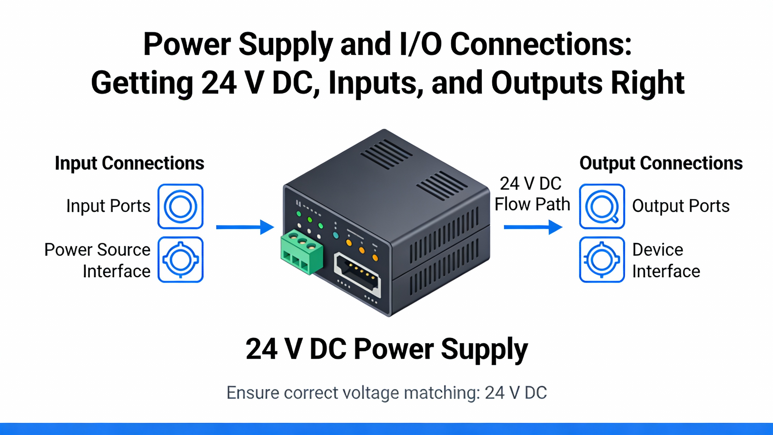
Power Supply and I/O Connections: Getting 24 V DC, Inputs, and Outputs Right
For an S7-1200 in a power-protection system, the 24 V DC supply is the backbone. Siemens documentation specifies that the controller must be supplied from a stabilized 24 V DC source within the stated tolerance. Installation guides recommend separate feeders, fuses, and breakers for the CPU, I/O modules, and field loads so a short in one area does not drop the entire controller. In a UPS-backed control panel, this often means tapping the 24 V DC from a DC UPS or a power supply that is itself fed from a UPS-protected AC source, with individual protection devices for each branch.
Your wiring diagram needs to show that separation explicitly. Draw distinct 24 V DC circuits for the CPU supply, for I/O module electronics, and for field devices such as solenoids and lights, each with its own protective device and clearly labeled common return. Indicate polarities clearly on the S7-1200 power terminals and on any distribution terminals. Industrial wiring guides stress the importance of double-checking polarity and tightening terminal screws; reversing +24 V and 0 V or leaving a connection loose is still one of the fastest ways to damage or destabilize a PLC.
On the I/O side, Siemens guidance recommends grouping digital inputs and outputs by common reference. For example, a block of inputs may share the same 24 V DC common or 0 V reference. Your diagram should reflect these groups so that a technician can see, at a glance, which sensors share the same reference and how that reference returns to the power supply and protective earth. For outputs, make sure your drawing traces the complete load path from the S7-1200 output terminal, through any intermediate relay or contactor, to the load and back to the supply.
A real-world case from a Siemens support forum illustrates why this matters. In a university demonstration rig built around an S7-1212C AC/DC/RLY, the program loaded correctly and the outputs Q0.0 and Q0.1 showed as active in the engineering software. However, the physical LEDs and buzzer controlled by those outputs never turned on. The department had wired an extra relay in the output circuits even though that CPU already had relay outputs, and the way that relay was wired prevented current from ever reaching the loads. From a wiring diagram perspective, the issue was that the diagram did not clearly show how the power would flow through both the internal and external relays. If you cannot follow a continuous circuit from 24 V DC, through the output device, to the load, and back, your diagram is not finished.
Inductive loads such as contactor coils and small relays are common on S7-1200 outputs, especially in switchgear and UPS transfer applications. Siemens wiring guidelines recommend using RC snubbers, varistors, or free-wheeling diodes on those loads. The purpose is to limit overvoltage when the current is interrupted, which protects relay contacts and reduces electromagnetic interference. Your diagram should indicate which suppression method is used at each inductive load. While this detail might seem minor, it is directly tied to how long your relay contacts and output modules last under repetitive switching.
Analog I/O deserves special attention in noisy power rooms. Siemens recommends shielded, twisted-pair cables for analog signals and notes that these cables should be routed away from switching devices and high-current conductors. Your wiring diagram should clearly distinguish analog cables from digital ones, including termination details for the shields and any reference or sense connections. Typical S7-1200 analog ranges include 0ŌĆō10 V and 4ŌĆō20 mA; the devices you connect must be compatible and configured accordingly in the control program. Industry articles on S7-1200 installation highlight the need to check transmitter ranges and wiring before commissioning to avoid misinterpretation of process values.
A concise way to capture the key decisions for each I/O type is to summarize them visually.
| I/O type | Key wiring focus | Reliability consideration |
| Digital input | Common reference, debounced contacts | Prevents false triggers from poor reference sharing |
| Digital output | Load path, output current limits, suppression | Protects contacts and modules, reduces noise |
| Analog input | Shielded twisted pairs, short runs | Minimizes measurement error and drift |
| Analog output | Shielding, correct load impedance | Prevents overshoot and unstable control signals |
If you keep these elements front and center in your wiring diagram, the S7-1200 will behave predictably even when the power system around it is anything but predictable.
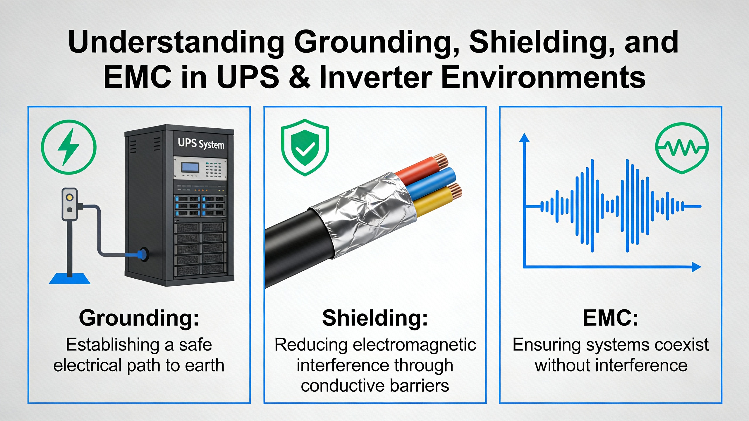
Grounding, Shielding, and EMC in UPS and Inverter Environments
When you place an S7-1200 near UPS cabinets, inverters, or variable-speed drives, you are working in a high-noise environment by definition. Fast switching edges, large currents, and magnetic fields are all present. SiemensŌĆÖ wiring guidelines emphasize that the way you wire grounding and shields is critical to preserving signal integrity and meeting electromagnetic compatibility expectations.
For analog signals and communication lines, Siemens recommends shielded, twisted-pair cables with shields connected using short, wide, low-impedance connections to a common reference, typically the control cabinet ground. The emphasis on short and wide is not cosmetic; it reduces the inductance of the connection and makes the shield more effective over a broad frequency range. In practice, this often means clamping shields to a grounded bus bar or rail directly near the cabinet entry, rather than running shield drains long distances inside a duct.
Loop area is another concept Siemens highlights. Whenever outgoing and return conductors are physically separated, they form a loop that can pick up or radiate noise. The wiring guidance specifically recommends routing those conductors close together to minimize loop area. On a diagram, that translates to showing paired conductors and discouraging separate, wandering routes for positive and negative lines. In a UPS room, keeping the positive and negative conductors of a 4ŌĆō20 mA loop bundled together, for example, makes that loop far less vulnerable to the magnetic fields around transformer leads.
Siemens also encourages the use of metallic cable ducts or screens where needed, and stresses keeping sensitive lines away from contactors, drives, and transformers. In a practical sense, your wiring diagram should identify cable types and duct routes in enough detail that installers understand which paths are acceptable for shielded Ethernet, analog signals, and digital I/O, and which are reserved for AC feeders or inverter output cables.
Grounding itself is both a safety and a performance issue. The S7-1200ŌĆÖs ground connection should be tied to a proper earth ground, and the control cabinet should be bonded in line with local electrical codes and relevant IEC or EN standards. Many installation guides for the S7-1200 also talk about SELV or PELV circuits for control voltage, which are defined by their limited voltage and isolation characteristics. Your diagram should indicate where SELV or PELV boundaries exist, and how those circuits relate to the rest of the grounding system.
A common failure mode that shows up in the field is erratic analog readings or intermittent communication when shields are either left floating or grounded in an inconsistent way. SiemensŌĆÖ emphasis on using a common reference point and clear shield terminations aims to prevent exactly this kind of behavior. When your diagram clearly shows which end of each shield is grounded, where it lands in the cabinet, and how that point connects to protective earth, technicians are far less likely to improvise changes that compromise EMC performance.
Communication and Network Wiring: PROFINET and Beyond
For modern power systems, the S7-1200 is rarely a standalone device. It is typically networked via Ethernet to HMIs, SCADA systems, data historians, or other PLCs. Siemens and independent installation articles recommend shielded Ethernet cables for protocols like PROFINET and Modbus and emphasize correct IP setup just as much as correct wiring.
Physically, your wiring diagram should show the S7-1200ŌĆÖs built-in Ethernet port, any network switches or routers, and the path back to engineering workstations or supervisory systems. Shielded Ethernet cabling should be shown clearly, with notation for shield termination at cabinet entry and connection to the grounded cabinet structure. Just as with analog signals, Ethernet cables should be routed away from motor and inverter cabling as much as possible, and they should cross such cables at right angles when necessary.
Logically, every S7-1200 on the network needs a unique IP address and correct subnet configuration. SiemensŌĆÖ TIA Portal is used to configure those settings. A support thread on MrPLC describes a case where an engineer connected a PC directly to an S7-1200 and saw physical link indicators (a green link LED and blinking Rx/Tx LEDs) but could not get TIA Portal to go online with the CPU. The hardware was connected, but the PCŌĆÖs network settings and TIA Portal configuration were not aligned with the PLC. From a wiring standpoint, everything looked correct, yet the system was effectively disconnected.
The lesson for your wiring diagram is that it should not stop at showing cables and connectors. It should also document network segments, address ranges, and where those settings are configured. Including a small notation for IP addresses or at least for the subnet used by each network helps maintenance engineers quickly distinguish wiring faults from configuration issues.
In critical power applications, many operators now expect redundancy or at least robust diagnostic paths. While detailed network architectures are usually handled in separate documents, your S7-1200 wiring diagram should identify any diagnostic or maintenance ports, along with their relation to the main network. SiemensŌĆÖ own recommendations for troubleshooting often begin with connecting to the device and accessing an online diagnostics area, so the physical and logical network paths must be obvious.
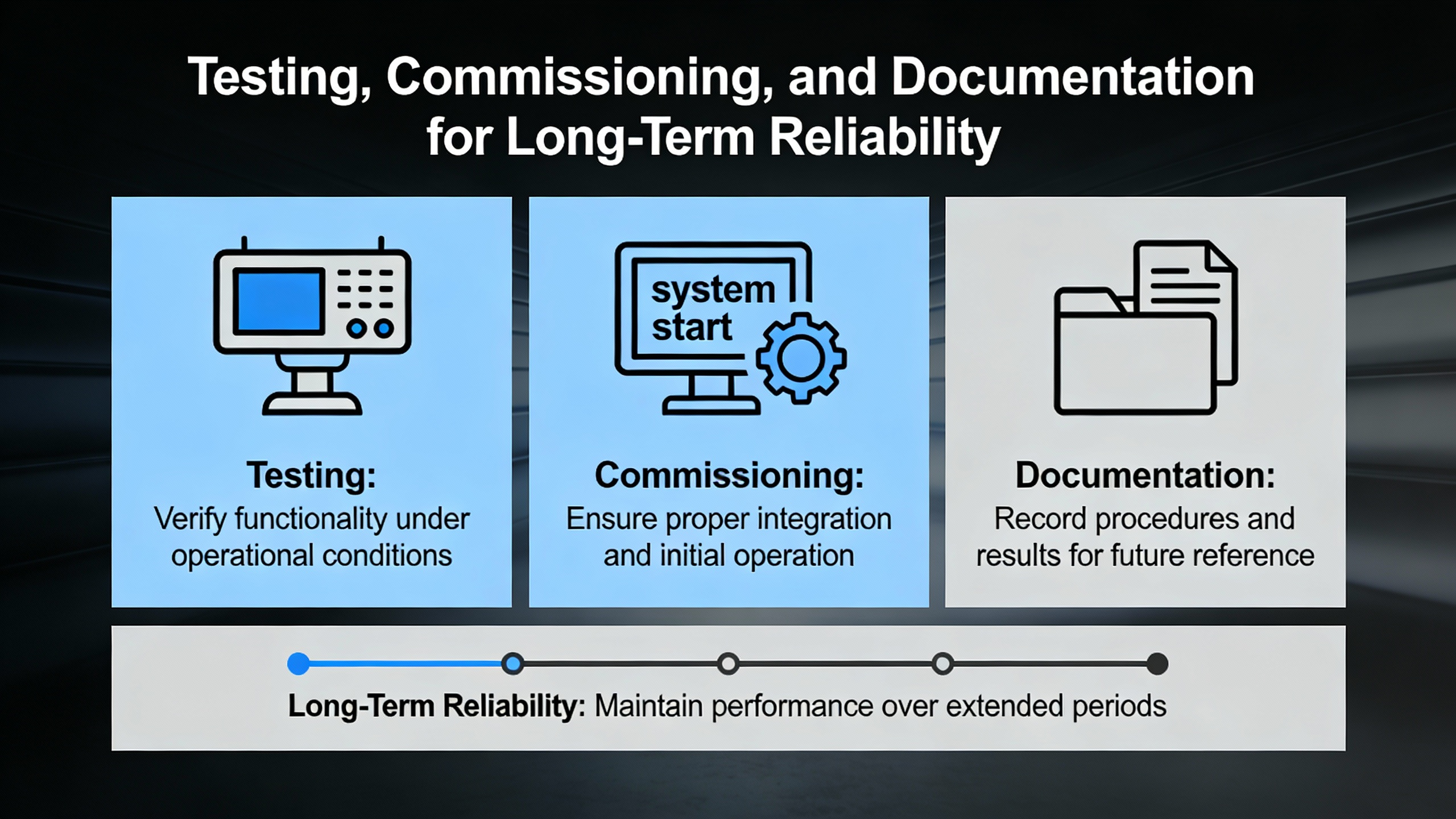
Testing, Commissioning, and Documentation for Long-Term Reliability
Even the best wiring diagram is only a plan; its value is proven during commissioning. SiemensŌĆÖ S7-1200 wiring guidance places heavy emphasis on verification and testing before a system is put into service, and independent installation articles echo that message.
Once wiring is complete, you should verify all terminal assignments, polarity, and insulation. In practice, this means checking that every conductor is landed on the terminal shown in the diagram, that positive and negative 24 V DC leads are not reversed, and that insulation is intact and appropriate for the voltages involved. Measuring the 24 V DC supply under load at the CPU and modules ensures that voltage drop and supply sizing are not issues; Siemens specifically advises measuring under load rather than at open circuit.
Grounding and shielding continuity should also be checked. Siemens recommends verifying that shields are correctly bonded to the intended grounding point and that cabinet bonding to protective earth is solid. For industrial technicians, a multimeter and basic continuity tests are standard tools here, as noted in industrial training programs for electrical technicians and in S7-1200 installation guidance.
Functional testing of I/O is the next step. An S7-1200 wiring guide from an industrial automation supplier describes a common approach: perform a power-up check to confirm that LEDs indicate normal operation, then use a multimeter to verify voltages at power and I/O points, and finally run a simple test program in TIA Portal that cycles each I/O channel to confirm correct wiring. This structured method turns the abstract diagram into a verified reality.
Troubleshooting examples from Siemens support forums underscore how valuable this stage is. In one reported case, an S7-1200 showed flashing LEDs and had stopped controlling its process. Experienced users advised going online with the PLC using the engineering tool, then opening the Online and Diagnostics area and exporting the diagnostics buffer. The red-marked entries in that buffer often pointed directly to faults that could be tied back to wiring issues such as short circuits or power interruptions. Without a diagram that accurately reflects how power and signals are wired, interpreting those diagnostics becomes guesswork.
Documentation is the final pillar of reliability. Siemens wiring guidelines encourage labeling all conductors, using ferrules or suitable terminals, and arranging wiring so that circuits are visually traceable and separated by function or voltage level. Your wiring diagram should align with that physical labeling scheme: terminal numbers, cable designations, and shield termination points should match between the drawing and the panel. Siemens and automation training materials also emphasize that good documentation supports future troubleshooting and modifications, which is critical in long-lived power systems where equipment may outlast the original project team.
In the context of UPS-backed and inverter-based systems, thorough documentation becomes even more important. When maintenance personnel have to work under time pressure, perhaps during an outage or while the plant runs on generator power, a clear, accurate S7-1200 wiring diagram can be the difference between a quick, safe fix and a risky improvisation.
Closing Perspective as a Reliability Advisor
When you wire a Siemens S7-1200 into an industrial or commercial power supply system, you are not just drawing lines between symbols. You are defining how that controller will behave during the worst five minutes of the year: a utility disturbance, a transfer to UPS or generator, or a fault on a critical feeder. If your wiring diagram respects SiemensŌĆÖ segregation, grounding, and power-supply guidance and if it tells a clear story about how power, signals, and communication move through the system, the S7-1200 will reward you with stable, predictable performance. Investing that care upfront is one of the simplest, most cost-effective reliability upgrades you can make in any UPS or inverter control project.
References
- https://www.academia.edu/110773772/Design_and_Implementation_of_a_Solar_Panel_Data_Monitoring_System_Based_on_PLC_S7_1200
- https://commons.erau.edu/cgi/viewcontent.cgi?article=1169&context=jdfsl
- https://catalog.wctc.edu/courses/605/605.pdf
- https://www.coastalpines.edu/economic-development/continuing-education/industry-trades/electrical-technician
- https://manor.edu/academics/adult-continuing-education/online-offerings/electrical-tech/
- https://upcommons.upc.edu/server/api/core/bitstreams/27e15f7b-cd9a-4420-9fa6-086986cf07ce/content
- https://do-server1.sfs.uwm.edu/file/+2T9434R776/doc/4T5283R/electrical+engineering+handbook+siemens.pdf
- https://www.plctalk.net/forums/threads/plc-wiring-questions.96057/
- https://industrialautomationco.com/blogs/news/essential-wiring-and-mounting-tips-for-the-simatic-s7-1200-controller?srsltid=AfmBOoqksDLyW1VcaS27S92umnmNqciSOuRd64tb34VsMb6pthwRmJdF
- https://plcai.app/plc-ai-blog/f/siemens-plc-wiring-the-ultimate-guide-to-s7-1200-and-s7-1500


 Videos
 News
News Applications


Leave Your Comment