Why Fieldbus Still Matters On A Power-Intensive Factory Floor
Walk into any modern manufacturing plant and you will see a lot of attention paid to transformers, UPS systems, inverters, and switchgear. Yet, from a reliability perspective, the system that quietly determines whether those assets are actually controlled safely and efficiently is the communication backbone connecting sensors, drives, protection relays, and controllers. That backbone is still, very often, a fieldbus network.
Industrial fieldbuses are families of digital communication networks designed specifically for real-time distributed control. Standards such as IEC 61158 and IEC 61784 define them as serial, multi-drop, bi-directional networks that connect programmable logic controllers (PLCs) and distributed control systems to field devices including sensors, actuators, motors, valves, contactors, and meters. Academic analyses of fieldbus technology and reference sources emphasize the same core motivation: replace bulky point-to-point wiring and 4ŌĆō20 mA loops with a shared, intelligent bus that cuts cable, lowers lifecycle cost, and improves diagnostics while maintaining high availability and deterministic behavior.
From a power-system reliability angle, that determinism and diagnostic depth matter. A UPS that never reports an overload alarm to the PLC, or a motor-protection relay that cannot warn of rising temperature, is a latent failure waiting to surface at the worst possible time. Fieldbus technology, when correctly selected and engineered, is one of the most cost-effective ways to keep that data flowing, even in electrically noisy, power-dense environments.
In my own work evaluating factories after major outages, I regularly see two patterns. Plants that invested early in structured fieldbus networks, with clear protocol boundaries and robust physical-layer design, recover faster from power disturbances and are easier to troubleshoot. Plants that relied on adŌĆæhoc mixes of direct wiring and under-engineered communication often spend more time chasing intermittent faults than they do fixing the root power problem. The difference is rarely the brand of UPS or breaker; it is usually the discipline in how devices talk to each other.

The Basics: What A Fieldbus Network Really Is
From Point-to-Point Wiring To Shared Digital Buses
Traditional control wiring connected each instrument directly back to a controller. A single pressure transmitter needed its own twisted pair for a 4ŌĆō20 mA loop; an individual on/off valve required its own discrete pair. That model scales poorly: a machine with hundreds of devices demands hundreds of cables, hundreds of terminations, and a control room filled with marshalling cabinets.
Fieldbus replaces that with a shared digital cable. Authoritative standards work and product selection guides describe a fieldbus as a digital, serial, multi-drop data bus used to communicate with low-level control and instrumentation devices. Instead of one cable per device, many devices share a single trunk that may branch into drops. Data is encoded, often with self-clocking methods such as Manchester coding, and transmitted over copper or fiber with well-defined physical-layer variants. Some fieldbus variants even carry both DC power and communication on the same two conductors, so a single twisted pair powers and controls multiple devices.
Practically, that means a fieldbus segment can aggregate dozens or even hundreds of measurement and command points into one controller connection. Global product guides cite examples where a Foundation Fieldbus H1 segment can support up to 240 devices per segment over roughly 6,200 ft of cable, while other protocols like LONWorks support tens of thousands of nodes in a domain over distances on the order of 6,600 ft. In process-style fieldbuses such as Foundation Fieldbus or PROFIBUS PA, a single trunk can typically host up to 32 devices, and many practitioners deliberately derate that to around 12 devices per segment for reliability and hazardous-area constraints.
From a wiring perspective, the savings multiply quickly. If you have 24 motorized breakers or UPS modules that previously would each require a dedicated analog loop plus status contacts, moving them onto a single shared bus can eliminate hundreds of terminations. Less copper, fewer terminations, and a simpler drawing set mean fewer opportunities for human error.
Where Fieldbus Sits In The Automation Hierarchy
Industrial networking literature often describes four communication levels. At the lowest layer, sensor buses link basic devices like limit switches. Above that, device buses connect sensors and actuators along with drives and motor control centers. Control buses coordinate PLCs and instruments tied to HMIs. At the top, enterprise buses move information between plant systems and business IT.
Fieldbus networks typically span the sensor and device bus layers and form the lower edge of the control bus. They directly connect drives, I/O blocks, protective relays, power meters, and intelligent UPS or inverter interfaces to PLCs and distributed controllers. Higher-level networks, increasingly based on Industrial Ethernet, aggregate this data to SCADA, MES, and cloud platforms.
In practice, your motor control centers, switchgear, and power quality equipment may speak one set of protocols (for example, PROFIBUS, DeviceNet, Modbus, or IEC 61850 over Ethernet), while your packaging machines and conveying systems might rely on EtherCAT or PROFINET. ABBŌĆÖs fieldbus guidance explicitly notes that optimized control-system architectures often combine several fieldbus families and that electrical integration protocol choice should follow what the equipment supports, whether that is IEC 61850, EtherNet/IP, or PROFIBUS.
Timing, Determinism, And Local Intelligence
Industrial communication is not just about moving bits; it is about moving them on time. Research on fieldbus technology emphasizes three core performance attributes: determinism, real-time behavior, and repeatability. Determinism is the guarantee that a message will be delivered within a known time bound. Real time is the end-to-end reaction time from change at the input (say, a voltage dip) to corresponding output action (trip, transfer, or load shedding). Repeatability is the ability to deliver that performance consistently.
Most fieldbus protocols address these needs in two ways. First, they define controlled media-access mechanisms: token passing, masterŌĆōslave cycles, or producerŌĆōconsumer models. That keeps bus arbitration predictable, instead of letting devices speak whenever they like. Second, they push intelligence into the field. Many field devices contain microprocessors that can run local control functions such as PID, alarming, and interlocks. Foundation Fieldbus in particular is designed so that control loops can execute entirely in field devices; a Link Active Scheduler orchestrates a repeating macrocycle, during which inputs execute, devices publish values, control blocks calculate outputs, and actuators update. If the controller or network link is lost, local logic can often continue to maintain a safe state.
From a power-reliability standpoint, local control is valuable. A breaker or static transfer switch that can execute fast protections locally while merely reporting status to the PLC is inherently more robust than one dependent on a central controller for every trip decision.

Comparing Major Fieldbus Families For Manufacturing
There is no single ŌĆ£bestŌĆØ fieldbus. Instead, there is a landscape of protocols optimized for different industries, performance levels, and legacy ecosystems. Reference materials from connector and cable suppliers, standards bodies, and industrial network vendors consistently highlight a common set of families.
Classic Serial Fieldbuses
Modbus is one of the earliest and simplest fieldbus protocols. Originating as a masterŌĆōslave serial bus, it remains widely used in building and industrial automation because it is open, easy to implement, and supported by many devices. It is often chosen when compatibility and simplicity matter more than cutting-edge speed.
PROFIBUS, short for Process Field Bus, is one of the most deployed fieldbuses worldwide, with tens of millions of installed nodes reported by user organizations. It offers variants for process automation (PROFIBUS PA) and discrete or factory automation (PROFIBUS DP). Its data link layer uses a token-passing method that supports masterŌĆōslave and multi-master configurations, with both cyclic and acyclic communication. This combination of flexibility and determinism has made it popular in both manufacturing and process industries.
DeviceNet is a CAN-based fieldbus developed by Rockwell Automation and standardized in EN 50325-2. It uses the Common Industrial Protocol (CIP) and is widely used in PLC-centric manufacturing networks, especially in North America. CANopen, another CAN-based protocol, is prevalent in mechanical engineering and vehicle technology, valued for robustness and real-time behavior, though it tends to serve smaller networks compared with some Ethernet-based options.
Foundation Fieldbus targets process industries such as refining, power generation, food and beverage, and pharmaceuticals. It is an all-digital, bi-directional, multi-drop system designed as a local area network for instrumentation and control devices. Its advanced features include standardized device descriptions, capability files, and support for executing control loops directly in field devices, along with rich diagnostics. A Foundation Fieldbus H1 segment runs at a standardized 31.25 kbit/s and, as mentioned earlier, can connect dozens of devices in parallel.
Real-Time Ethernet Fieldbuses
Since around the early 2000s, a range of Real-time Ethernet fieldbuses has emerged, building on standard Ethernet physical layers but modifying or constraining higher layers to achieve deterministic behavior. Industrial Ethernet technologies such as EtherNet/IP, PROFINET, EtherCAT, and various Powerlink variants leverage EthernetŌĆÖs speed and ubiquity while adding mechanisms for real-time scheduling.
Industrial communication vendors and engineering guides characterize EtherCAT as a high-performance protocol that supports flexible topologies such as line, star, tree, and ring, and is well suited to automation tasks that demand very low latency and precise synchronization. PROFINET and EtherNet/IP, on the other hand, are widely deployed for discrete manufacturing tasks such as conveyors and automotive body shops, where millisecond-level update times are sufficient.
Independent comparisons of fieldbus and Ethernet-based solutions note that Industrial Ethernet has gained ground because it offers higher data rates, longer connection distances, and more nodes than many traditional serial fieldbuses. However, they also stress that for connecting field-level equipmentŌĆösensors, actuators, and local power devicesŌĆöclassic device and fieldbus networks often remain the simplest and least expensive choice.
Protocol Families In Context
Multiple guides and vendor-neutral overviews emphasize that protocol selection is inherently application-specific and region-specific. PROFIBUS is particularly strong in Europe, Modbus is widely used in North America and in building automation, CANopen and DeviceNet are prominent where CAN-based machinery dominates, and Foundation Fieldbus has a deep installed base in process plants and power-generating facilities.
EtherCAT, PROFINET, and EtherNet/IP collectively serve a large and growing share of new discrete automation projects, especially where motion control and tight synchronization are essential. In many plants, these Real-time Ethernet technologies sit above or alongside classic fieldbuses, rather than replacing them outright.
The result is that many factories operate mixed networks: perhaps PROFIBUS PA segments for process instrumentation, DeviceNet segments for motor starters, and EtherNet/IP or PROFINET links for line-level coordination. ABBŌĆÖs application notes explicitly recommend combining several fieldbus types in an optimized control architecture instead of force-fitting one protocol everywhere.
The table below condenses key information from multiple technical sources to summarize several common fieldbus families relevant to manufacturing environments.
| Protocol family | Typical use in manufacturing and power-related systems | Selected characteristics from references |
| Modbus (RTU/TCP) | General-purpose industrial and building automation; legacy integration | Simple, open, masterŌĆōslave serial bus; widely supported and easy to deploy |
| PROFIBUS DP/PA | Factory automation, drives, and process instrumentation | One of the most widely deployed fieldbuses; token-bus MAC; cyclic and acyclic communication |
| DeviceNet | PLC-based manufacturing networks, motor control centers | CAN-based; object-oriented CIP; strong in North American factory automation |
| CANopen | Mechanical equipment and vehicles, embedded systems | CAN-based; robust, real time; commonly used in embedded and vehicle applications |
| Foundation Fieldbus | Process industries and power generation instrumentation | All-digital, multi-drop; control-in-the-field; standardized device descriptions and diagnostics |
| EtherNet/IP | Discrete automation, electrical integration, plant-wide networking | Industrial Ethernet using CIP; supports integration of electrical equipment |
| PROFINET | Factory automation, motion control, high-speed manufacturing | Industrial Ethernet with real-time extensions; widely adopted with PROFIBUS |
| EtherCAT | High-performance motion and control, synchronized machinery | Real-time Ethernet with flexible topologies and very low latency |
Choosing Fieldbus Architectures For Factory Automation And Power Assets
When advising plants on communication architecture, I usually hear a variation of the same three questions: which protocol or stack should we choose, how much of the legacy fieldbus should we keep versus replacing with Ethernet, and how do we make sure the network will behave under real-world electrical stress?
Start From The Application, Not The Fashion
Technical primers from standards organizations and independent reviewers emphasize that fieldbus proliferation exists because industrial applications differ. Manufacturing automation fieldbuses emphasize short reaction times over a few hundred yards, while process automation networks emphasize long distances and intrinsic safety, and building automation networks emphasize scale and integration over wide areas.
ABBŌĆÖs guidance synthesizes this into a simple rule: new continuous, analog-style process installations often benefit from Foundation Fieldbus for instrument and control integration; new discrete, on/off or batch-oriented installations can benefit from PROFIBUS, PROFINET, DeviceNet, or EtherNet/IP. Electrical integration should reflect the protocols supported by switchgear, relays, and metering equipment, including IEC 61850, EtherNet/IP, and PROFIBUS.
Specialist communication-stack vendors echo a similar theme. EtherCAT is typically favored where high performance and precise synchronization are mandatory, for example in motion-heavy automation systems. CANopen suits a broad range of embedded industrial devices. For safety-critical applications, Safety over EtherCAT (FSoE) builds functional safety (aligned with IEC 61508) on top of EtherCAT. SAE J1939, also CAN based, serves vehicles and engine-driven equipment including power-generation sets. These recommendations illustrate a more general principle: match the protocol family to your dominant domain.
For a factory that must coordinate fast-moving packaging lines while also monitoring large UPS systems and generator sets, it is often sensible to combine technologies. Real-time Ethernet protocols may manage line control, DeviceNet or PROFIBUS might handle motor starters and distributed I/O, and protocols like J1939 could be used on engine controllers. The power-system view is to ensure that protection and critical control favor the most deterministic and robust links you can justify, while less critical monitoring can ride on more flexible networks.
Respect Your Installed Base And Vendor Ecosystem
High-level papers on fieldbus evolution emphasize the persistence of legacy standards such as Modbus, PROFIBUS, BACnet, and KNX. ABB likewise recommends that modernization projects start from the plantŌĆÖs current installed base of protocols, including HART, PROFIBUS, DeviceNet, and Modbus, and focus on integrating rather than ripping out networks.
Modern modular I/O platforms support that strategy. Some IP67-rated fieldbus modules and couplers can automatically detect and operate with different communication protocols, meaning you may only need to change the PLC or controller while leaving field wiring and modules intact. Others expose multiple protocol options (for example, PROFIsafe-capable modules combining safety inputs, standard I/O, and IO-Link master ports) so a single hardware family can serve several network types.
In practice, that means if your switchgear and UPS fleet already offer stable PROFIBUS or Modbus interfaces, it is usually more reliable to keep those segments and bridge them into higher-level Ethernet networks than to force everything into a single newly fashionable protocol.
Match Performance, Safety, And Environment
Academic overviews of fieldbus technology spend considerable effort classifying protocols by timing guarantees, media access control, and quality-of-service features. Industrial network selection guides similarly emphasize that you must quantify required data rates, update times, and robustness to electromagnetic interference before choosing a protocol.
If your process requires sub-millisecond reaction times, such as high-speed motion control, then Real-time Ethernet variants like EtherCAT or PROFINET IRT are appropriate. Process controls such as boiler drum levels or transformer oil temperatures often tolerate update cycles of one second or more, and thus fit comfortably in scheduled bus systems like Foundation Fieldbus H1 segments.
Safety adds another set of constraints. Foundation Fieldbus and PROFIBUS PA support intrinsic safety concepts, including standardized designs like FISCO (Fieldbus Intrinsically Safe Concept) and FNICO (Fieldbus Non-Incendive Concept), which control the energy available on trunks so that work can be done safely in hazardous areas. For EtherCAT-based systems, safety can be layered using protocols like FSoE that comply with functional safety standards. For installations with large numbers of emergency stops, some fieldbus-based safety systems can support networks with more than 2,000 emergency stop devices on a single safety PLC while still providing diagnostics on each stopŌĆÖs status and location.
Harsh electrical environments also drive physical-layer choices. Copper cabling is still dominant, especially twisted pair, because it is cost-effective and easy to install. Selection guides highlight that fieldbus cables must provide adequate shielding against electromagnetic and radio-frequency interference, particularly around high-current equipment and variable-speed drives. Cable jackets and insulation should withstand the plantŌĆÖs temperature and chemical exposure profile. Where interference or lightning risk is severe, fiber segments or galvanically isolated repeaters may be warranted.
For UPS rooms and main switchgear, I typically recommend placing fieldbus trunks and Ethernet cables away from high-current conductors, using shielded cables specified for the protocol (for example, those certified for Foundation Fieldbus or PROFIBUS), and paying close attention to bonding and grounding practices. These practices are consistent with the recommendations from cable and connector manufacturers that stress shielding, environmental resistance, and mechanical durability.
A Simple Segment Sizing Example
Foundation Fieldbus design guidance offers a helpful rule of thumb: assume each device consumes about 20 mA of current from the segment. If your Fieldbus power conditioner is rated for roughly 265 mA under a FISCO intrinsic-safety concept, dividing that rating by 20 suggests a realistic limit of about 12 devices per segment. This matches field experience and the conservative recommendations of many practitioners. Operating far below the theoretical maximum device count per segment leaves margin for cable losses, future growth, and real-world variations.
From a reliability perspective, this kind of calculation is no different than loading a UPS or inverter to a safe percentage below its nameplate rating. You accept lower apparent efficiency in exchange for robustness, especially during abnormal conditions.
Physical Layer And Topology Choices That Affect Reliability
Topology Tradeoffs: Bus, Star, Ring, And Tree
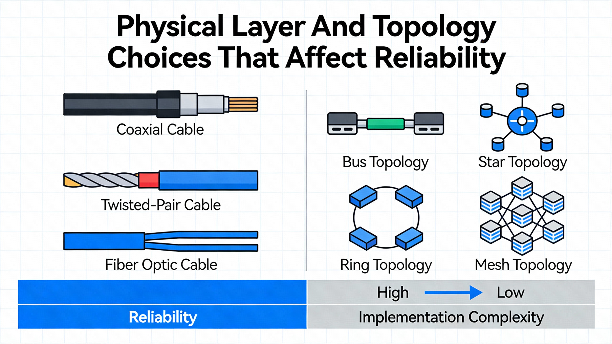
Fieldbus networks support a variety of topologies, and the choice has direct implications for fault behavior and maintainability. Reference materials and selection guides explain that classic bus topologies place devices along a single shared line. This wiring style is efficient in terms of cable usage but introduces single points of failure: a break in the main trunk can divide the network. Tree structures extend the bus with branches, helping match plant geography and isolating some failures to a branch.
Star topologies, where each node connects directly to a central hub or switch, simplify administration and fault isolation. Independent network design recommendations point out that if one star leg fails, the rest of the network continues operating, and it is easy to add or remove devices. This is one reason star-like arrangements are so common for Ethernet-based fieldbuses.
Ring topologies connect devices in a closed loop and are common in some fieldbus designs like INTERBUS, as well as in many Ethernet-based redundancy schemes. They can provide error resistance and continued operation despite a single cable break, as frames can travel in the opposite direction.
In real deployments, hybrid topologies are common. For example, you might have a trunk-and-branch bus for PROFIBUS segments feeding star-connected Ethernet switches. Or you may use EtherCAT, which supports combinations of line, star, tree, and ring, to form a topology that matches your machinery layout while still achieving deterministic performance.
Cables, Connectors, And Mechanical Design
Fieldbus cable and connector selection is not a cosmetic detail; it directly affects uptime. Technical guides on fieldbus cabling stress that users should analyze required data speeds, cable lengths, environmental conditions, and mechanical stress. For high-speed or long-distance runs, staying within protocol length limits is essential to preserve signal integrity. Shielding must be adequate to reject noise from drives, transformers, and switchgear.
Fieldbus connectors add another layer of design choice. Common families include M12 and M8 circular connectors, which are compact and robust, and RJ45 connectors for Ethernet-based fieldbus systems. Guidance from connector suppliers emphasizes matching connector type with cable type, ensuring that ingress protection (for example, IP67) suits the environment, and using secure locking mechanisms to prevent accidental disconnections. In harsh environments, IP67-rated modular I/O blocks mounted directly on machines can eliminate many control cabinets, saving floor space and reducing cabinet cooling loads, which in turn lowers stress on local power distribution.
When evaluating these components near UPS and power distribution areas, it is wise to select connectors with firm locking features and robust housings. Vibrations from large rotating equipment and thermal cycling around transformers can loosen marginally specified connectors; rugged industrial types are designed to tolerate these factors.
Diagnostic Features And Local Logic
Modern distributed I/O blocks and fieldbus modules often include deeper functionality than simple signal conversion. Some devices integrate field logic controller capabilities, meaning they can execute simple control logic locally. Others support advanced diagnostics such as per-channel short-circuit protection, voltage-status indication, and detailed fault codes.
Guidance from machine-automation solution providers notes that using wiring hubs or field device couplers with per-spur short-circuit protection prevents a single short from shutting down an entire Fieldbus segment. Voltage-status LEDs can help technicians immediately identify whether a trunk or spur has lost power. Some modules also support enhanced diagnostic protocols that allow monitoring systems to pinpoint which emergency stop device has actuated in networks containing thousands of safety devices.
In power-system terms, these features improve mean time to repair and reduce the likelihood that a minor wiring issue will escalate into a wide-area outage. They also allow maintenance teams to work more surgically during planned outages, minimizing the time systems have to run on backup power.
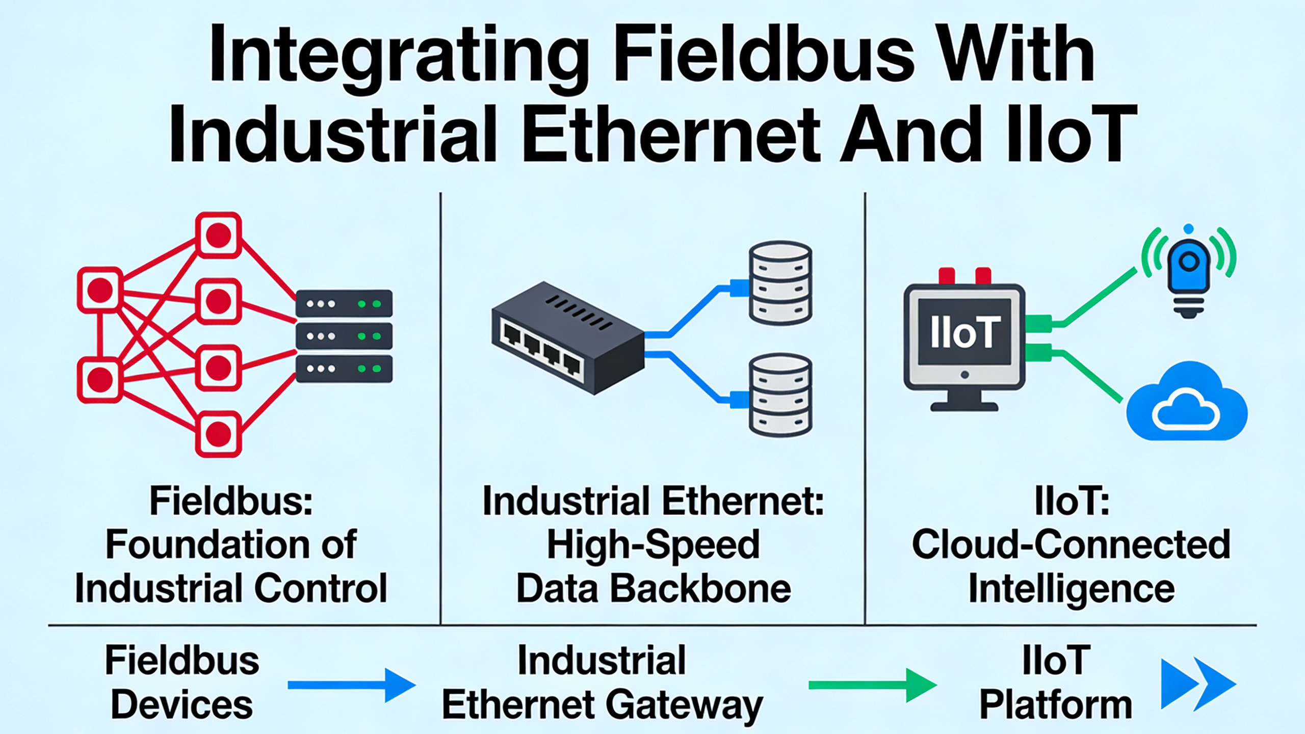
Integrating Fieldbus With Industrial Ethernet And IIoT
Fieldbus technology does not exist in isolation any more than a UPS does. Modern plants increasingly adopt architectures where fieldbuses handle device-level communication and Industrial Ethernet provides cell- and plant-level connectivity. Reference material on Industry 4.0 and Industrial Internet of Things (IIoT) emphasizes that fieldbuses remain critical for reliable, real-time device networking, while Ethernet and wireless links handle aggregation, analytics, and remote access.
Several sources describe this layering explicitly. Fieldbus networks connect field devicesŌĆösensors, actuators, and other control devicesŌĆöto central controllers. Industrial Ethernet refers to Ethernet protocols hardened for industrial environments, generally used for higher-level network communications. Technologies such as IO-Link Wireless fit at the device level as point-to-point or point-level interfaces that integrate into broader fieldbus or Ethernet architectures, enabling smart communication with individual devices without pulling additional cables.
Foundation Fieldbus provides a clear example of how traditional fieldbus is evolving to integrate with Ethernet. Its High Speed Ethernet (HSE) extension supports faster communication for complex, data-heavy applications while maintaining compatibility with slower H1 segments. Academic and industry analyses note that HSE and similar technologies help position fieldbus systems for IIoT use cases such as remote monitoring, predictive maintenance, and cloud-based analytics.
The practical takeaway for a factory integrating power systems is that you do not need to move every device to Ethernet to reap IIoT benefits. Instead, you can maintain robust, intrinsically safe fieldbus segments for instrumentation around generators, transformers, and UPS modules, and use gateways or Ethernet-based couplers to expose relevant data to higher layers. This approach limits the exposure of safety-critical networks to cyber risk while still enabling advanced monitoring and optimization.
Practical Design Guidance From A Reliability Perspective
Bringing the preceding concepts together, a reliability-focused approach to fieldbus in factory automation and power systems follows a sequence that mirrors good power-system design.
First, clarify the criticality and timing needs of each subsystem. Motion control on a high-speed packaging line, breaker interlocking in main switchgear, and UPS alarm monitoring each have different latency and determinism requirements. Use high-performance Real-time Ethernet where you truly need microsecond to millisecond control, but do not discount mature fieldbus protocols for slower, yet safety-critical, process variables.
Second, catalogue the installed base and vendor support. If your plant already runs thousands of PROFIBUS or DeviceNet nodes connected to drives and I/O, and your power protection devices speak Modbus or Foundation Fieldbus, build an architecture that integrates those segments rather than forcing them into a newly chosen protocol. This aligns with guidance from both system integrators and major automation vendors that urge leveraging existing networks and devices wherever possible.
Third, design physical layers with the same conservatism you apply to power circuits. Respect protocol limits on cable length and device count, and consider derating segment loads below theoretical maxima, as Foundation Fieldbus design rules suggest. Choose cables and connectors that match environmental and mechanical stresses, particularly around large electrical equipment rooms. Provide proper shielding, grounding, and cable routing to minimize electromagnetic interference.
Fourth, embed diagnostics and local intelligence. Select field devices and I/O modules that support rich diagnostics, standardized device descriptions, and local logic execution, whether through control-in-the-field features in Foundation Fieldbus or field logic controllers in modular I/O blocks. These capabilities make it easier to maintain a high-availability system under real operating conditions.
Finally, plan your migration path. Industry analyses of fieldbus standardization emphasize that Real-time Ethernet solutions have the potential to replace many traditional serial fieldbuses over time, but legacy installed bases will remain for decades. Architecting your system with gateways, multi-protocol modules, and clear network segment boundaries allows you to introduce new Ethernet-based layers as justified by new equipment, without destabilizing proven fieldbus segments that underpin critical protection and control.
From the reliability advisorŌĆÖs seat, the goal is not to chase the newest protocol. The goal is to create a communication network that lets your UPS, inverters, switchgear, drives, and process equipment exchange the right information, at the right time, with predictable behavior even during faults or partial outages.
Brief FAQ
Are classic fieldbuses like PROFIBUS and Modbus obsolete now that Industrial Ethernet is common?
Technical surveys of industrial networking consistently show that classic fieldbuses are still widely used, with large installed bases in manufacturing, process, and building automation. Industrial Ethernet is gaining share, especially for new discrete automation projects that need higher speeds and flexible topologies, but fieldbuses remain a simple, cost-effective way to connect many field devices. In practice, plants run mixed architectures where fieldbuses and Ethernet coexist.
How should I think about fieldbus choice for UPS and power distribution monitoring?
While individual product capabilities matter, guidance from automation suppliers and electrical integration notes suggests you start from the protocols that your power gear already supports, such as Modbus, PROFIBUS, EtherNet/IP, or IEC 61850-based solutions. Use those protocols at the device level and bridge them into your broader fieldbus and Ethernet architecture, choosing deterministic or intrinsically safe variants where required. This avoids forcing power equipment into unfamiliar communication schemes and respects its certification and safety assumptions.
What is the single most important design habit for a reliable fieldbus network?
Across academic, standards, and vendor guidance, one habit stands out: respect the physical layer. That means correct cable types, adherence to segment length and device-count limits, thoughtful topology selection, robust shielding and grounding, and conservative loading of power supplies and intrinsic safety barriers. When those basics are handled with the same rigor you apply to sizing a UPS or breaker, the logical aspects of protocol choice and addressing tend to fall into place far more smoothly.
In well-designed factories, fieldbus systems and Industrial Ethernet form the nervous system of automation, carrying the data that lets power systems do their work safely and reliably. Investing the time to design that nervous system properly is one of the most leveraged reliability decisions you can make.
References
- https://www.academia.edu/39203042/Fieldbus_Standard_for_Use_in_Industrial_Control_Systems_Part_2_Physical_Layer_Specification_and_Service_Definition
- https://en.wikipedia.org/wiki/Fieldbus
- https://ui.adsabs.harvard.edu/abs/2005IEEEP..93.1073T/abstract
- https://aichat.physics.ucla.edu/filedownload.ashx/virtual-library/kq9qEy/Configuration-Manual-For-Profibus-Pa-Fieldbus-Temperature.pdf
- https://etd.ohiolink.edu/acprod/odb_etd/ws/send_file/send?accession=osu1243606788&disposition=inline
- https://www.fieldcommgroup.org/technologies/foundation-fieldbus/foundation-technology-explained
- https://new.abb.com/control-systems/fieldbus-solutions
- https://www.amissiontech.com/news/a-comprehensive-guide-to-selecting-fieldbus-cables-and-connectors-for-industrial-automation.html
- https://www.automation.com/article/how-to-pick-the-right-fieldbus-protocol
- https://connectorsupplier.com/what-is-the-fieldbus-protocol/


 Videos
 News
News Applications


Leave Your Comment