Schneider ElectricŌĆÖs Modicon controllers sit at the heart of many powerŌĆæcritical systems where downtime translates directly to lost production, compliance exposure, or safety risk. In UPSŌĆæbacked switch rooms, data centers with dualŌĆæcorded loads, and mixed environments where VFDs and inverters share busbars with sensitive control electronics, every diagnostic second counts. This guide consolidates what matters most when you are face to face with a blinking CPU, a halted task, or a cryptic Modbus response. It reflects frontŌĆæline experience bringing Modicon M340, M580, Quantum, and compact controllers back from faults, and it aligns with Schneider documentation and community guidance for credibility and repeatability.
Why Error Codes Matter in PowerŌĆæCritical Automation
Fault codes are not just alarms; they are the systemŌĆÖs best attempt to explain what blocked execution, degraded performance, or broke communications. In a power reliability context where a UPS, inverter, or static transfer switch masks supply anomalies, a PLC may still flag a blocking application error, a module communication failure, or a fieldbus exception. The right reaction sequence prevents unnecessary power cycles, protects drives and process equipment, and preserves data integrity. The wrong reactionŌĆölike clearing a fault without understanding its causeŌĆöoften turns a recoverable blip into extended downtime.
How Schneider Classifies PLC Faults
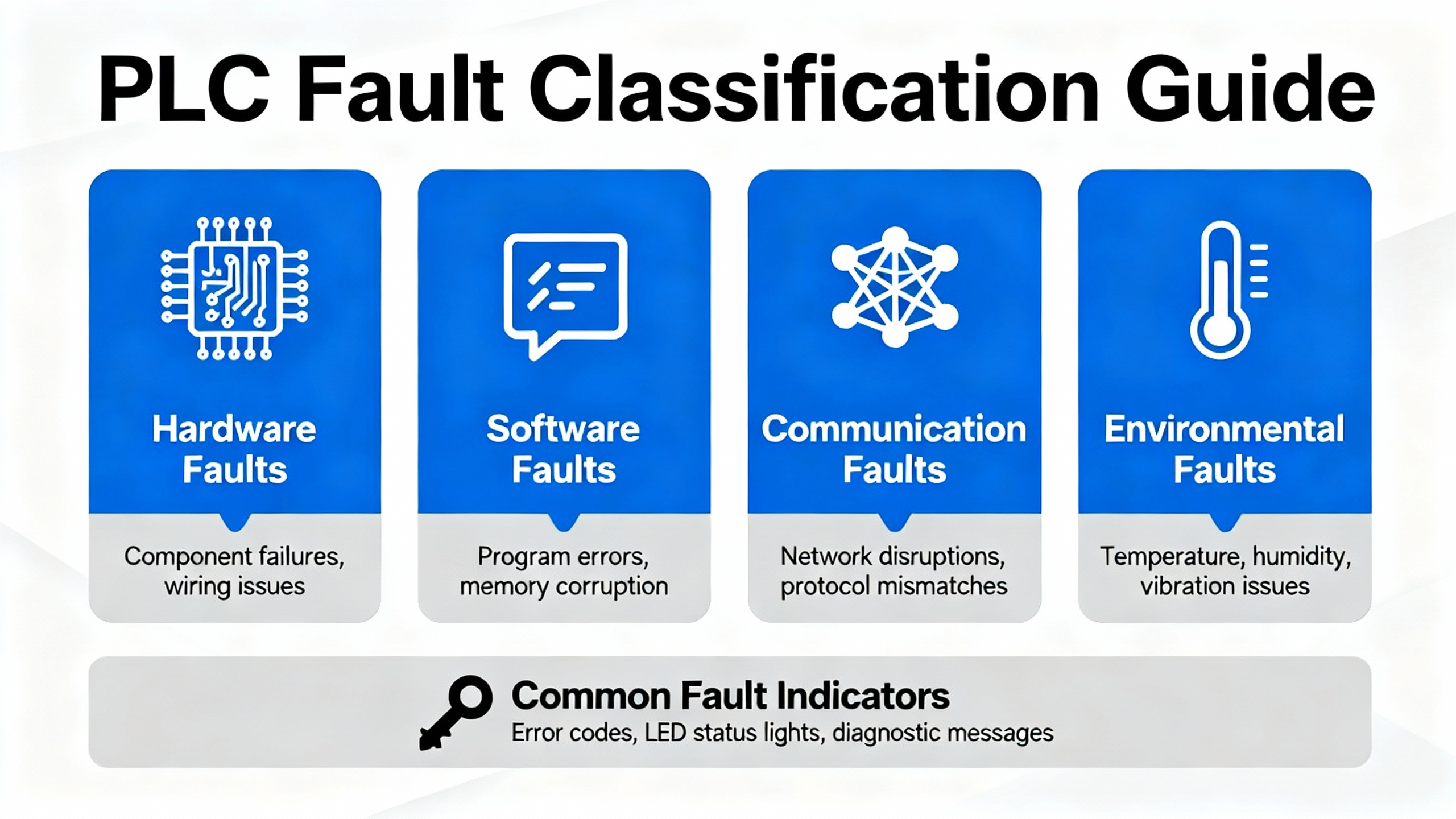
Schneider classifies PLC errors into nonŌĆæblocking, blocking, and processor or system errors. NonŌĆæblocking conditions may log events while logic continues. Blocking errors are applicationŌĆæcaused conditions that halt execution; the controller enters HALT and the ERR indicator flashes. Processor or system faults indicate deeper issues, for example memory integrity or executive firmware integrity on legacy platforms. On Modicon M340, Schneider defines this specifically through frontŌĆæpanel LEDs and system words, giving you a deterministic path from symptom to root cause rather than guesswork. That taxonomy should guide your first look at LEDs and your second look at diagnostics registers.
M340: Decoding LEDs, System Words, and HALT Recovery
The Modicon M340 provides a clear set of frontŌĆæpanel indicators for PLC state, memory card access, and network activity across Modbus Serial, CANopen, and Ethernet. Error detection occurs at startup and during runtime, and there are three levers every troubleshooter should internalize. First, a blocking error places the CPU in HALT with the ERR LED flashing. Second, the instruction address that caused the halt is published to system words %SW126 and %SW127, and the error nature is coded in %SW125. Third, recovery without a download is possible: initialize the PLC or set system bit %S0 to 1, which returns the application to its initial state where data values revert, the input image refreshes, outputs go to their fallback, and the application can be returned to RUN once safe. Use only SchneiderŌĆæapproved SD media on M340, as the memory system is validated for flash endurance of approximately 100,000 write and delete cycles and the access LED is behind the protective cover. When you support a site with strict change control, these indicators are often the cleanest way to confirm whether an event was environmental, applicationŌĆædriven, or a storage/media compatibility issue.
| M340 Indicator or Register | Meaning or Source | Where to Check | First Action |
| ERR flashing, HALT | Blocking error from application | Front panel LEDs | Initialize PLC or set %S0 to 1, then return to RUN after verifying safety |
| %SW125 | Encoded error nature | Controller diagnostics in Control Expert (Unity Pro) | Decode value to determine instruction or resource fault type |
| %SW126, %SW127 | Address of offending instruction | Controller diagnostics | Inspect that logic location online; correct bad parameters or illegal operations |
| SD access LED | Memory card activity and health prompt | Behind protective cover | Use only Schneider SD cards; avoid nonŌĆæqualified media to prevent integrity faults |
| CANopen and Ethernet LEDs | Network health per module | BMX NOM 0200 and BMX NOE 01x0 module LEDs | Use moduleŌĆælevel indicators to narrow bus or IP issues before rewriting code |
The immediate practical implication is straightforward. When the ERR LED flashes on M340, go to the system words before changing anything. If the fault traces to bad parameter ranges or an outŌĆæofŌĆæsequence instruction, fix that. If it points at communications resources, move downŌĆæstack into module LED states and network cabling before attempting to reload an application.
Quantum Run LED Blink Groups: Reading Crash Codes Without Guesswork
Legacy Modicon Quantum CPUs frequently appear in facilities where power system modernization is staged over years. These controllers expose a compact but powerful fault scheme using the Run LED blink count to identify a code group and a hexadecimal crash code to specify the condition. The method is consistent and fieldŌĆæfriendly: count the blinks to select the group, then read the hex to find the specific fault. Indicators like Ready, Run, Modbus/Modbus Plus, Mem Prt, Bat Low, and Error A further constrain your search.
| Run LED Blink Pattern | Domain Focus | Example Codes | Practical Cue |
| Continuous with 0000 | Kernel state | 0x0000 | Usually an intentional or requested kernel mode |
| Two blinks | RAM sizing and runtime stack | 0x80B, 0x80C, 0x82E | Review memory sizing and runtime handler stability |
| Three blinks | ASIC and backplane bus | 0x769, 0x72A, 0x72C, 0x730 | Focus on bus grants, DPM writes, and ASIC health |
| Four blinks | UPI and communications | 0x604, 0x607, 0x614, 0x616, 0x61EŌĆō0x631 | Check timeouts, buffer overflow, MBP interface, UART hardware |
| Five blinks | RAM and processor selfŌĆætests | 0x503, 0x52D | Investigate memory integrity and POST results |
| Six blinks | RAM data integrity | 0x402 | Validate module and board memory paths |
| Seven blinks | Executive firmware health | 0x300, 0x301 | Reload or verify executive; consider repair path |
| Eight blinks | PROM/flash integrity | 0x8001, 0x8002, 0x8003 | PROM checksum and flash program/erase issues demand firmware service |
When Error A is lit red, the fault relates to Modbus Plus communications. In practice, that steers you to termination, shielding, and interface health before deeper CPU service. For seven or eight blinks, escalate to executive reload and vendor service after capturing blink count and hex code. This approach has resolved more Quantum incidents on power and water plants than any speculative reprogramming effort.
Modbus Exceptions: What the PLC Is Telling You
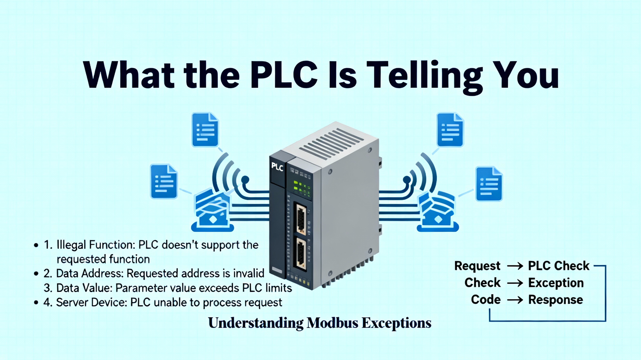
Modbus remains the lingua franca of industrial communications across Modicon families. When a slave device rejects a request, the reply echoes the function code with its high bit set and includes a oneŌĆæbyte exception code. The combination is intentionally minimal so you can diagnose deterministically, even over constrained links. Time invested in interpreting these codes pays back in hours saved chasing phantom wiring issues.
| Exception Code | Name | Typical Cause | First Fix |
| 01 | Illegal Function | Function not supported by the target | Confirm function support for the device profile; choose a valid function |
| 02 | Illegal Data Address | Invalid or unimplemented register/coil address | Verify register map and offsets; align Object Type and start addresses |
| 03 | Illegal Data Value | OutŌĆæofŌĆærange value or quantity | Correct value ranges and requested lengths; respect device limits |
| 04 | Slave Device Failure | Unrecoverable device error while acting | Log event and escalate; try again after device self diagnostics |
| 05 | Acknowledge | Long operation accepted, not complete | Poll again later; add backoff to request cycle |
| 06 | Slave Device Busy | Device occupied with other tasks | Retry with delay and schedule requests to avoid contention |
| 07 | Negative Acknowledge | Extended function disallowed in current state | Place device in an allowed state; review mode transitions |
| 08 | Memory Parity Error | Memory parity issue detected | Retry after diagnostics; consider device maintenance |
| 0A | Gateway Path Unavailable | Routing issue through gateway | Verify gateway routing and path configuration |
| 0B | Gateway Target Failed to Respond | No response from end device behind gateway | Check addressing, reachability, and timeouts across the hop |
On the PLC side, modular communication blocks surface their own statuses. Across Modicon families you will encounter Done, CommError, and OperError outputs or status words that encode faults. Error values often arrive in decimal, and decoding the bits in binary pinpoints which parameter or state transition failed. In my experience, failed multiŌĆæregister reads and outŌĆæofŌĆæwindow address ranges are the two most common culprits, especially when the engineering team swaps devices midŌĆæproject without updating register maps.
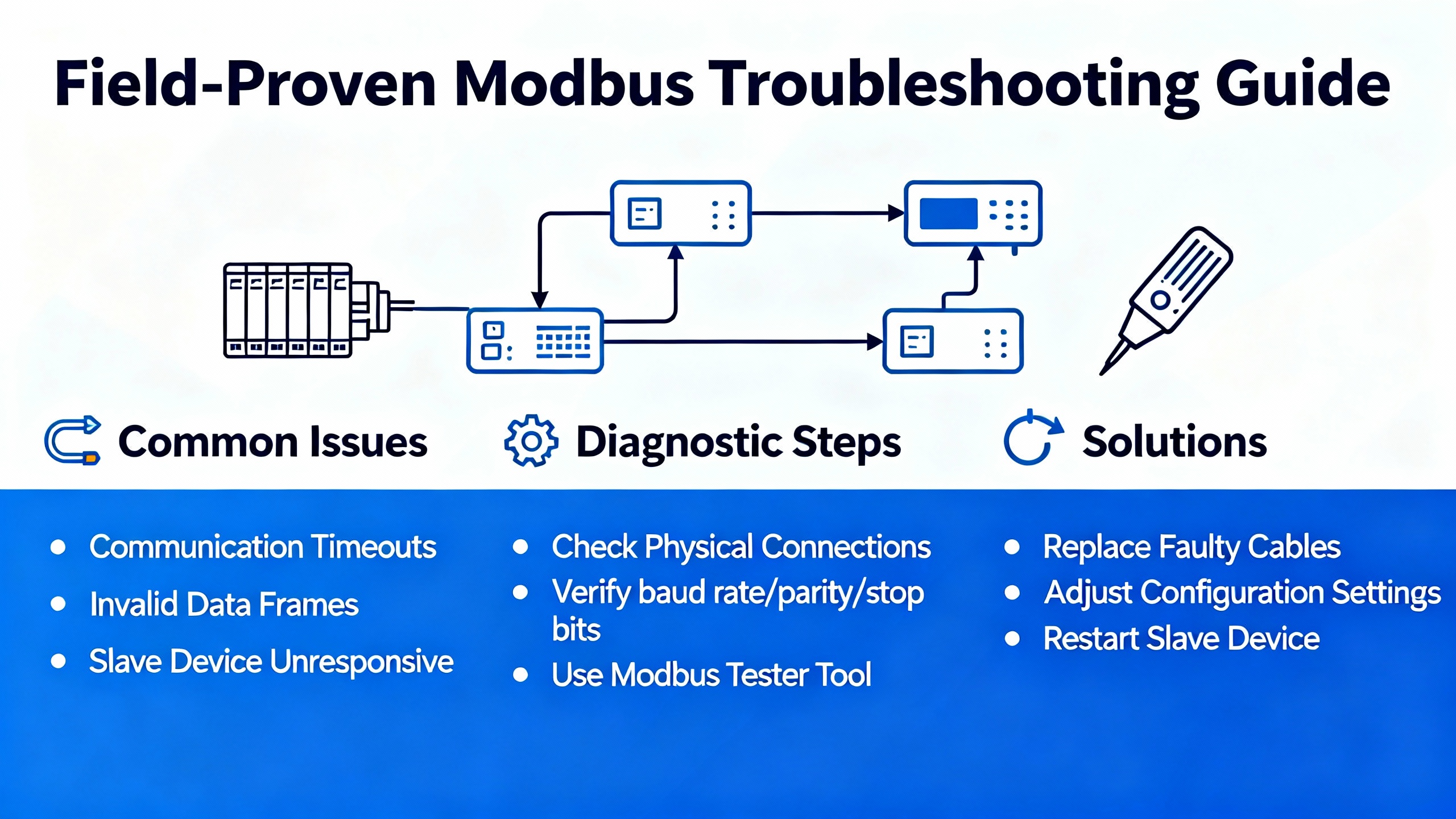
FieldŌĆæProven Modbus Troubleshooting on Modicon
SchneiderŌĆÖs environmentsŌĆöMachine Expert Basic for compact controllers, SoMachine legacy tooling, and Control Expert for M340, M580, Quantum, and PremiumŌĆöpromote a common discipline. Use read_var and write_var blocks to frame Modbus requests and verify every parameter. The health of Link, ID, Object Type, First Object, and Quantity determines whether you exchange data or you fill error lists. Mismatched lengths are a frequent root cause; for example, a device that only exposes three contiguous registers will fault if you request four. Modbus only processes one request at a time, so drive each block with a clean pulse and stagger the timing. Firing requests simultaneously invites busy responses and timeouts that are misdiagnosed as wiring errors.
Address hygiene matters. Do not reuse the same PLC memory address for multiple transactions or map overlapping ranges. Duplicates can block exchanges, corrupt buffers, or create race conditions that are almost impossible to reproduce on the bench. In Machine Expert Basic, confirm that a Write_Var mapping such as PLC %MW10 to device register 40001 actually saturates the intended field variable and not a neighboring holding register. In SoMachine, use ADDM to convert a port and slave string like 2.6 into a proper address structure, use single variables for singleŌĆæregister transactions, and arrays for multiŌĆæregister reads so you do not overflow buffers inadvertently. The device tree provides immediate visual feedback: green icons confirm communication and red flags require attention. In Control Expert, learn the channel address conventions early. For a BMX NOM 0200 serial module, a string like 1.5.1.2 means rack one, slot five, channel one on the dualŌĆæport interface, and slave ID two. SchneiderŌĆÖs management parameter array GEST or MNG_PARA5 includes a timeout element; for Modbus RTU, setting the third element to zero can trigger an automatic reinitialization after link recovery. On serial links this avoids full power cycles or project downloads after transient disruptions, something I have used repeatedly on generatorŌĆæbacked sites where serial noise appears during transfer events. For Modbus TCP, Control ExpertŌĆÖs IO Scanner is a productivity win because it eliminates bulk code and cyclically maps remote registers to local memory so long as you avoid overlapping ranges.
| Modbus Setup Field | What It Means | Common Pitfall | What to Confirm |
| Link | Port or channel selection | Wrong port on multiŌĆæchannel modules | Match physical channel to project topology |
| ID | Slave address | OffŌĆæbyŌĆæone on devices that number differently | Align numbering scheme across vendor docs |
| Object Type | Function code mapping | Choosing coils vs holding registers incorrectly | Confirm function code per device register map |
| First Object | Start register or coil | Offsets because of 0ŌĆæ vs 1ŌĆæbased addressing | Validate exact start address with a known good read |
| Quantity | Number of points | Requesting more than the device exposes | Reduce length to documented contiguous range |
| PLC Memory | First local word/bit | Overlapping or reused ranges | Reserve nonŌĆæoverlapping buffers with clear ownership |
Control Expert IO Scanner or Code Blocks?
There are two clean paths to Modbus TCP on M340 and M580. IO Scanner in Control Expert maps remote registers via the Ethernet module configuration. Code blocks like read_var or write_var give you programmatic control. One is not universally better; it depends on the architecture, change control posture, and the predictability of the remote device update rate.
| Approach | Strengths | Constraints | Best Use |
| IO Scanner (TCP/IP) | Simplifies configuration, cyclic mapping, fewer rungs | Not for serial RTU; avoid overlapping memory | Stable networks where point lists are known and steady |
| Code Blocks | FineŌĆægrained control of timing and retries | More code, greater maintenance | Dynamic or conditional polling, flexible retry logic |
Control ExpertŌĆÖs IO Scanner exists to avoid maintaining bulky communication rungs for Modbus TCP. For serial links you still need communication blocks, and you should tune timeouts and intervals carefully to avoid congesting the line or starving necessary transactions.
Power and Environment: The Hidden Variables Behind Many PLC Errors
A blocking error does not have to signify a poor program. In many troubleshooting engagements the root cause is in the power chain or ambient conditions. Confirm that the control power supply and its UPS maintain the correct voltage under load transients and that battery health is verified. Inspect fuses and breakers and do not ignore basic cabinet hygieneŌĆöventilation, fans, and dust removal are not cosmetic tasks in hot industrial summers. Loose terminations on I/O and communication modules are a recurring source of intermittent faults that masquerade as protocol errors. Firmware mismatches and overdue updates can manifest as inconsistent behavior, so maintain a controlled process for applying vendor updates and ensure version compatibility across the stack. These are bedrock principles of reliability that keep PLC diagnostics meaningful rather than noisy.

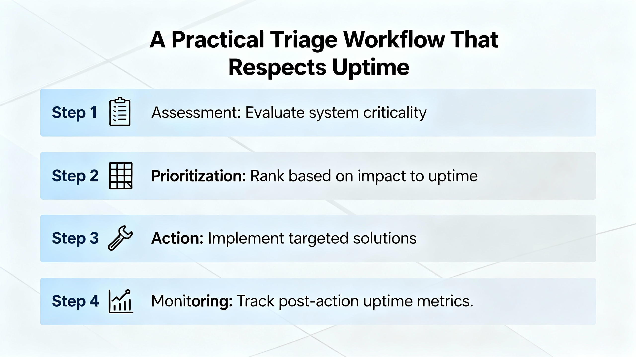
A Practical Triage Workflow That Respects Uptime
Begin with symptoms, not theories. Capture exactly what failed, when it began, and what preceded it. If a conveyor fails to start after a facility transfer to generator power, consider the power event part of the causal chain. Verify supply voltages with a meter and inspect LEDs on the CPU and communication modules. Decode LED patterns rather than clear them. Move to I/O status in software and verify that inputs and outputs reflect realŌĆæworld conditions. Inspect and test suspect sensors and actuators to isolate failing field devices. Review recent logic changes and watch online execution to confirm that enabling conditions are met; persistent watchdog or timer failures often trace to conditional logic that never becomes true. Where hardware suspicion remains, swap a module with a known good spare to observe whether the fault follows. Only then is it time to escalate to Schneider support, armed with error codes, LED patterns, and a coherent timeline. A stepwise approach keeps operations informed and reduces the trialŌĆæandŌĆæerror that burns time while systems remain down.
Two Quick Case Studies
A Modicon M340 at a water treatment site halted under load with ERR flashing. The diagnostics were conclusive. System words %SW126 and %SW127 pointed at a compute instruction receiving an outŌĆæofŌĆærange parameter, and %SW125 identified the fault type. Correcting the configuration prevented recurrence, and the system returned to service by setting %S0 to 1 and issuing RUN after confirming process safety. No power cycle was necessary, no media swap was required, and the controls team gained a specific lesson about validating ranges before commissioning.
A legacy Quantum CPU in a cement operation showed four Run LED blinks and communications instability. The hex code mapped to buffer and interface timeouts in the UPI and Modbus Plus domain. Rather than reloading the application, the team focused on the communication path. ReŌĆæterminating the bus, correcting shield bonds, confirming baud and node configs, and verifying UART hardware restored stability. Error A on the front panel corroborated the path and provided closure for root cause documentation.

Preventive Practices That Reduce Repeat Faults
The fastest way to resolve a future fault is to never see it. Keep clean reserve ranges for PLC memory used by communications and avoid overlap. Pulse and stagger Modbus request blocks and never fire multiple commands simultaneously. Treat register maps like controlled documents and ensure the program and field device models match precisely. Maintain backups of programs and module configurations with version control and enforce clear change control. Use SchneiderŌĆæapproved SD cards in controllers that support them and replace media proactively as part of lifecycle management. On serial Modbus links, tune timeouts and consider enabling automatic link reinitialization via management parameters so that transient disturbances do not demand a power cycle or download to recover. From a power chain perspective, verify that upstream UPS units and power supplies are sized correctly, the cabinet temperature stays within specification, and dust both outside and inside the enclosure is removed on a schedule. These disciplines keep your error logs limited to real issues rather than a river of avoidable noise.
Short FAQ
What is the difference between a nonŌĆæblocking and a blocking error on Modicon PLCs?
A nonŌĆæblocking error logs an issue while logic continues to run. A blocking error halts execution; the CPU enters HALT, ERR flashes, and on M340 the fault location and nature are published to system words. Recovery involves initializing the PLC or setting system bit %S0 to 1 and then returning to RUN once the underlying cause is corrected.
Should I choose Control Expert IO Scanner or communication blocks for Modbus TCP?
Use IO Scanner when you have a stable register list and want simple, cyclic mapping with minimal code. Use code blocks when you need conditional polling, custom retry logic, or dynamic sets of points. Avoid overlapping memory ranges in either approach. For Modbus RTU serial, use communication blocks and tune timeouts.
How do I triage Modbus exceptions like Illegal Data Address or Illegal Data Value?
Illegal Data Address means the requested register or coil does not exist at that location. Illegal Data Value means the supplied value or the quantity requested is outside of limits. Confirm the deviceŌĆÖs register map, align start addresses and function codes, and reduce requested lengths to documented contiguous ranges. For busy or acknowledge responses, add retry logic with backoff.
Credible Sources Behind This Guidance
The practices and code interpretations presented here align with Schneider ElectricŌĆÖs Control Expert and Knowledge Base guidance on M340 troubleshooting and communications, with Schneider Community explanations of Modbus exceptions and configuration, and with fieldŌĆæproven procedures summarized by Balaji Switchgears and Industrial Automation Co. The Quantum LED blink interpretations are consistent with service guidance from the MRO Electric technical team, and the Modbus diagnostic tables map directly to SchneiderŌĆÖs exception definitions.
Closing
Reliability starts with disciplined interpretation. When you treat every LED pattern, system word, and exception code as structured data rather than a nuisance, Schneider Modicon controllers become easier to support and your powerŌĆæcritical processes spend less time at risk. If you want help tailoring these diagnostics for a specific M340, M580, or Quantum architecture, I can translate this method into your plantŌĆÖs standards and point lists without adding operational complexity.
References
- https://do-server1.sfs.uwm.edu/upload/492782Z6S9/course/93451ZS/modicon_plc__programming-manual__tsx3708.pdf
- http://mcsprogram.org/libweb/u33A5B/244581/Schneider%20Plc%20Training%20Manual.pdf
- https://balajiswitchgears.com/plc-troubleshooting-and-diagnostics-common-problems-and-solutions/
- https://eltra-trade.com/blog/schneider-electric-altivar-71-fault-codes
- https://automizeindustry.blogspot.com/2020/12/troubleshooting-modbus-communication-in.html
- https://industrialautomationco.com/blogs/news/how-to-troubleshoot-plc-issues-step-by-step-solutions?srsltid=AfmBOopk1zUkqiXyb9eARy6JXJXaXp4P83wCN6SYrVSv0YKQj_3alYK0
- https://www.mroelectric.com/blog/schneider-140cpu11302-troubleshooting/
- https://www.plcdepartment.com/blogs/plcblog/tips-and-tricks-for-troubleshooting-plc-issues-in-the-field?srsltid=AfmBOorODfRkxbbn_ujSxy96PP3Tp7BsQEPgCjWBEdCuMM4G5coRrBak
- https://www.scribd.com/document/728381901/diagnostics-and-troubleshooting-schneider-electric
- https://cdn.automationdirect.com/static/manuals/ea9rhmim/appxa.pdf


 Videos
 News
News Applications


Leave Your Comment