Schneider contactors sit at the heart of motor control centers, UPS bypass panels, and inverter-fed switchboards, switching current thousands of times under real production conditions. When a contactor misbehaves, the consequences ripple across uptime, safety, and warranty exposure. In plants I support, production losses easily tally into hundreds or thousands of dollars per minute, which is consistent with industry guidance from DigiŌĆæKey TechForum. This article distills field-proven practice and reputable guidance to analyze and correct electrical contact failures in Schneider contactors. The goal is to help reliability and maintenance teams find root cause quickly, restore service safely, and prevent repeat events.
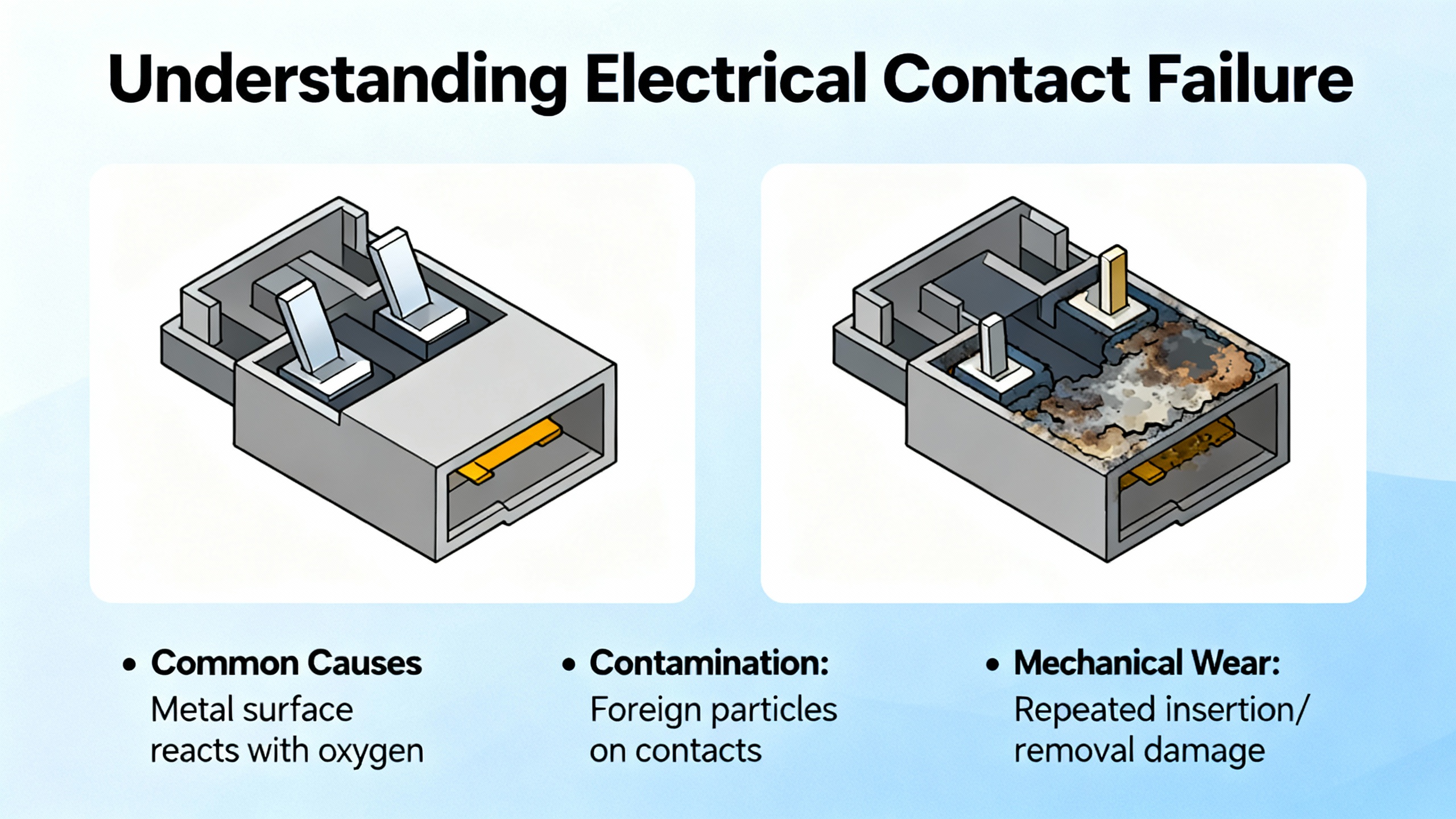
What ŌĆ£electrical contact failureŌĆØ really means
A contactor is an electromechanical power switch. A control coil creates a magnetic force that pulls an armature, which closes main contacts to carry load current, and opens them when deŌĆæenergized. Auxiliary contacts provide feedback to control and safety logic. In AC contactors, a shading coil in the pole face reduces vibration at waveform zero crossings. Definitions and test practices here align with Schneider Electric documentation, GEYAŌĆÖs testing guide, and maintenance tips summarized by Balaji Switchgears.
Electrical contact failure is a broad umbrella with several distinct end states. Eroded or pitted contacts from normal arcing raise resistance and heat. Uneven wear or contamination leads to hot spots and intermittent conduction. Fusion welding locks a pole closed. Misalignment or insufficient spring force reduces contact pressure. None of these should be brushed off as cosmetic. Each changes contact resistance, temperature rise, and the energy released during the next opening event, and each accelerates the march toward an unsafe failure.
Why Schneider contactor contacts fail in service
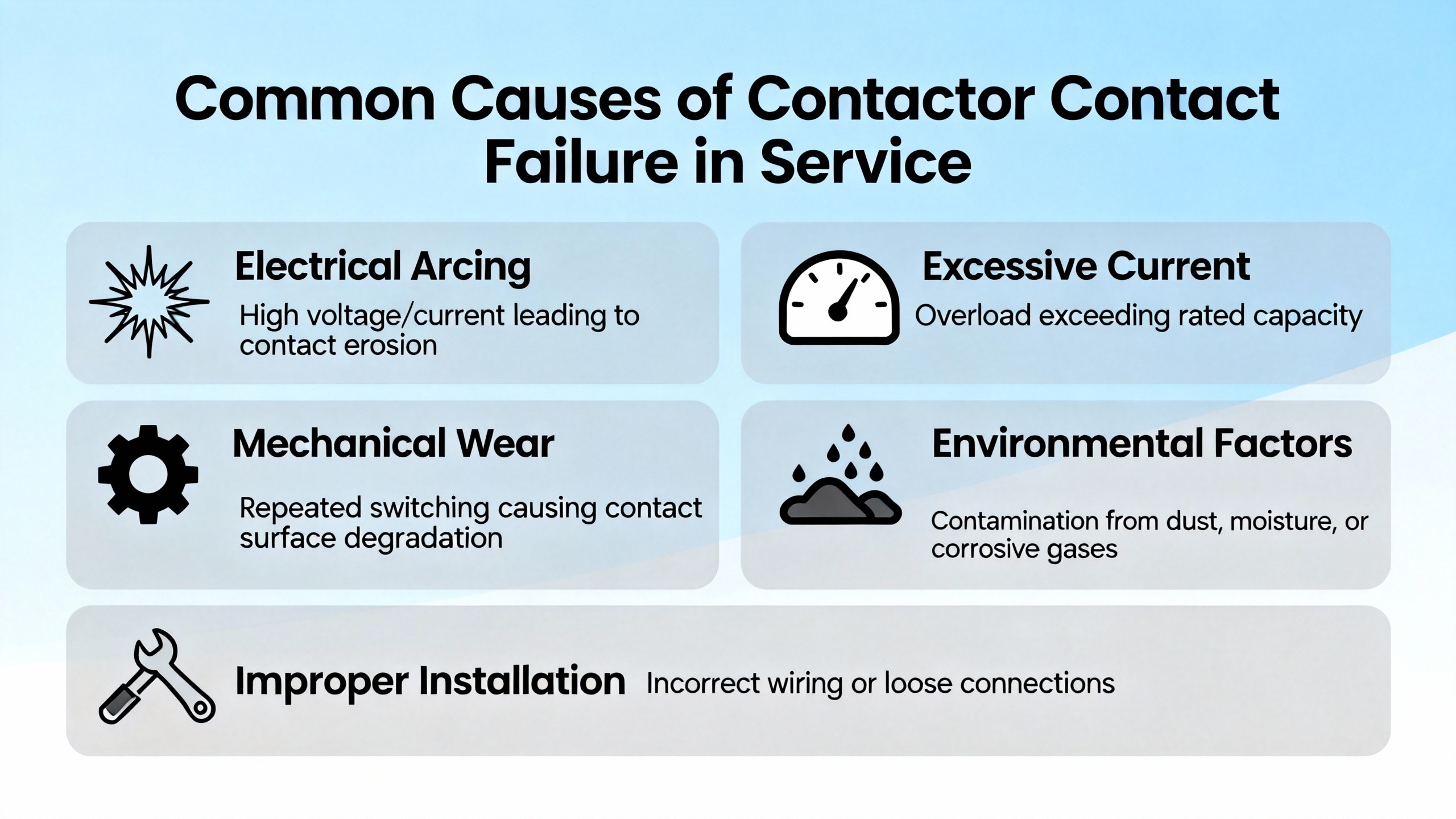
In real cabinets and MCCs, contact failures rarely have a single cause. The physics are straightforward: current, voltage, arc energy, and heat. The realities are messy: undervoltage chattering, terminal looseness from vibration, air-borne dust or oil film preventing a full magnetic seal, and short-circuit energy that overwhelms the contact system. ATOŌĆÖs troubleshooting guide and Schneider ElectricŌĆÖs coil guidance both highlight the compounding effect of undervoltage and poor sealing. When the armature cannot fully seat, the coil never reaches its higher sealed impedance, so it runs hotter and the contacts land with less force, which promotes chatter and burn marks. Schneider ElectricŌĆÖs FAQ explains this ŌĆ£sealedŌĆØ versus ŌĆ£unsealedŌĆØ distinction and warns that a coil can overheat at both too-low and too-high control voltage.
Short circuits and heavy overloads drive a different failure. ATO notes that a downstream short or debris on contact faces can weld contacts shut, and that low spring pressure or chatter from poor control loop design worsens the risk. On the opposite side, contamination on pole faces creates an air gap, reducing magnetic force and making noise and heating more likely; CHINTŌĆÖs engineering blog describes the characteristic hum and buzz of an AC armature losing holding force. Environmental and installation factors matter as well. Balaji Switchgears emphasizes dust, loose terminations, and thermal management in enclosures. Schneider Electric advises keeping the local air temperature around the contactor at or below roughly 140┬░F and watching for hotspots rather than quoting only overall cabinet temperature.
Protection and application choices influence the duty that contacts see. Digests from BIN95 and Mike Holt forum discussions remind us that the coordination of breakers, fuses, overload relays, and starters determines the letŌĆæthrough energy a contactor must survive. In particular, using the right type of upstream breaker and ensuring proper motor overload sensing through all legsŌĆöeven in singleŌĆæphase starters that require looping one leg so all three sensors see currentŌĆöprevents nuisance trips and unintended heating. Correct utilization category and duty (for example, ACŌĆæ3 versus ACŌĆæ4 under IEC practice, as raised in Schneider ElectricŌĆÖs community) also determine how much arcing energy contacts must handle per operation.
Symptoms, diagnostics, root causes, and corrective actions
Clear mapping between what you see, what you measure, and what you should fix speeds recovery and improves safety. The following table synthesizes failure signatures that recur in Schneider contactor work, paired with focused tests and the strongest drivers reported by Schneider Electric sources, ATO, GEYA, CHINT, Balaji Switchgears, and Control.com.
| Symptom observed | Focused checks | Likely root causes | Effective corrective actions |
| Dark discoloration, pitting, or uneven wear on main contacts; rising temperature under load | Measure contact resistance closed; compare poles; listen for chatter under control | Arc wear from utilization duty; repetitive chatter from undervoltage; misalignment or debris on faces | Replace worn contacts or the contactor; correct control voltage to nameplate; clean to OEM guidance; verify spring force only with OEM parts |
| Contacts welded closed; motor runs with no command | De-energize and test continuity; inspect for downstream short or fused metal droplets | Load-side short circuit; severe overload; debris and insufficient contact force | Clear downstream short; correct sizing/coordination of SCPD and overload; replace contactor; address debris and spring setting per OEM |
| Loud hum, buzzing, or chattering, especially at pull-in | Measure coil voltage under load; inspect pole faces; check shading coil on AC types | Undervoltage; phase imbalance; contaminated pole faces; degraded shading coil | Restore proper voltage; retorque and clean mating faces; replace coil or contactor if shading ring is compromised |
| Coil running hot or burning out repeatedly | Measure inrush and sealed voltage; inspect for mechanical obstruction; verify cabinet hotspots | Unsealed operation from poor seating; over- or undervoltage; high ambient air; obstruction preventing full travel | Keep local air around the device near 140┬░F or lower; correct supply voltage; ensure full mechanical travel; add ventilation as Schneider Electric advises |
| Failure to pull in on command; coil OK on bench | Verify PLC output voltage at coil; compare across outputs on the same card; check return/common | PLC output point failure; open conductor; incorrect control wiring | Reassign to spare output to confirm; repair field wiring; replace output module after field fault correction |
| Nuisance overload trips in singleŌĆæphase starter | Inspect overload wiring pattern; verify that all three sensing elements see current | Incorrect OL wiring that bypasses one or more sensors | Loop one phase through sensors as per starter instructions; follow manufacturer diagrams |
An additional note on temperature: do not rely on cabinet nameplate temperature alone. SpotŌĆæcheck where the air actually flows around the contactor frame. Schneider Electric indicates that air immediately adjacent to the device is what matters for coil life, and forced air circulation is recommended if passive cooling produces hotspots.
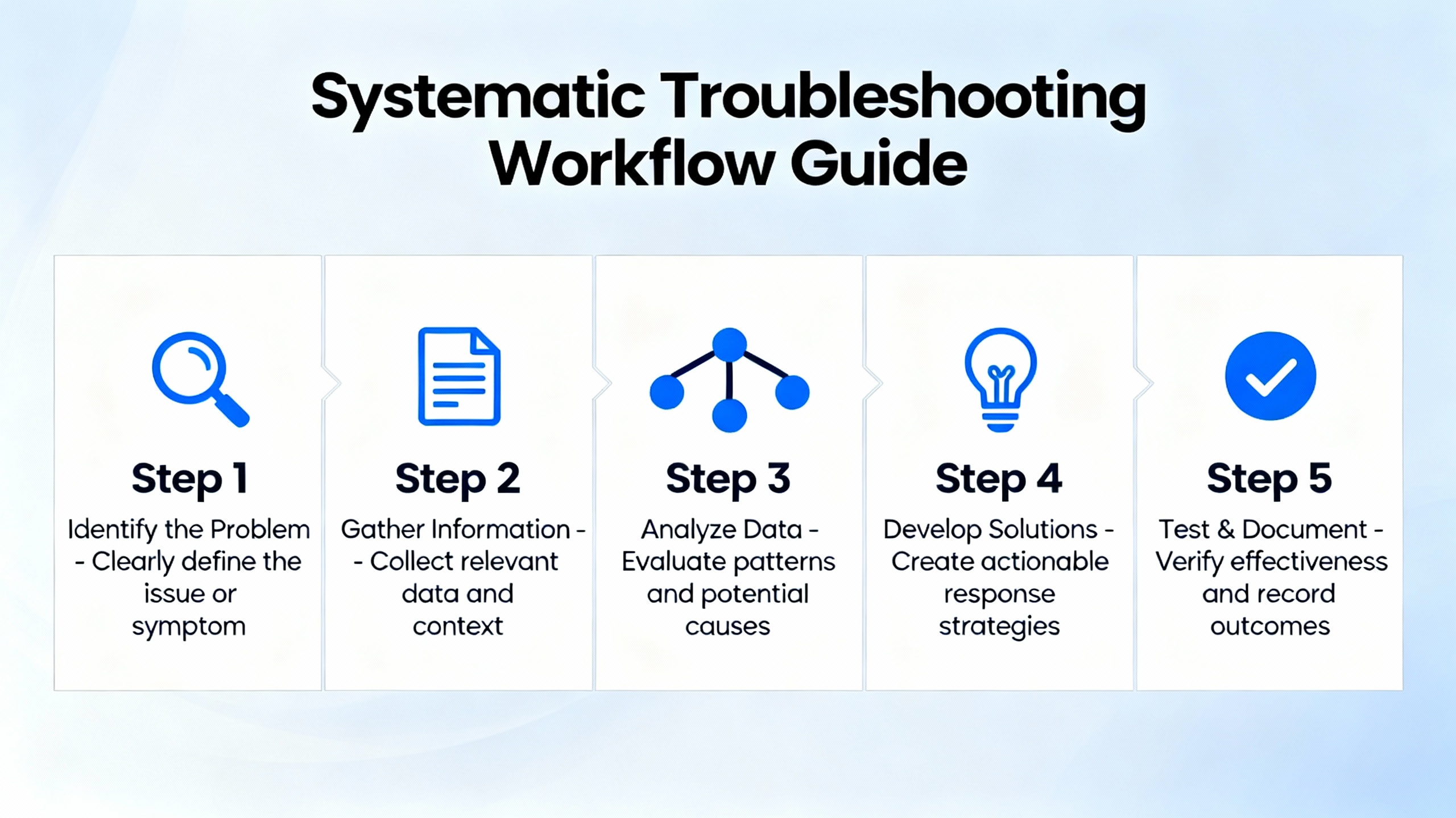
A systematic, stepŌĆæbyŌĆæstep troubleshooting workflow
High availability comes from discipline more than heroics. The best technicians follow a consistent path and record findings as they go.
Start with safety. Apply lockout/tagout, verify absence of energy, wear PPE, and use insulated tools. Elliot Services, NTT Training, and DigiŌĆæKey TechForum all emphasize that safe work practices, including twoŌĆæperson verification on highŌĆæenergy gear, are nonŌĆænegotiable.
Move next to a deliberate visual and tactile inspection. Look closely for heat tint on contacts and lugs, melted insulation, stray copper strands at terminals, dust and oil on pole faces, and mechanical damage or misalignment on the armature. Smell for burnt insulation. Gently move the armature by hand with the device deŌĆæenergized to feel for binding.
Verify the control path electrically. Measure coil voltage at pullŌĆæin and sealed. For common industrial systems this control level is often in the 24ŌĆō30 V range for DC or AC control, but confirm the Schneider nameplate and the actual design. If voltage sags below nameplate under load, find the drop by checking the supply, outputs, and wiring terminations. If a PLC is in the loop, trace the inputŌĆætoŌĆæoutput logic, watch the PLC input and output LEDs, and confirm that the output channelŌĆÖs voltage appears at the contactor coil. BIN95 and DigiŌĆæKey TechForum provide helpful sequences for confirming power at disconnects, branch protection, transformer secondaries, and the DC power supply that feeds PLC and control devices. If a single PLC output channel is suspect, bench tests and reassignment to a spare channel are a quick way to isolate a failed point without buying a new card prematurely, as practitioners have described in ElectricianTalk discussions.
Test the coil and contacts directly. With the coil isolated, measure resistance; an open or zero reading typically indicates a failed coil, and GEYAŌĆÖs guide recommends comparing to manufacturer expectations. Close the contactor under safe conditions and measure across each pole; significantly elevated milliohm values relative to peers indicate wear or contamination. Operate the device and time closing and opening; sluggish motion often points to low control voltage or mechanical drag.
Differentiate contactor versus downstream load problems. If the contactor looks healthy by electrical tests yet the motor or load behaves abnormally, step into the motor branch. BIN95ŌĆÖs motor workflow suggests megging windings to ground, comparing phase resistances within a tight band, and inspecting current symmetry. Low insulation resistance to ground or imbalanced winding resistances are motor-side issues, not contactor issues. Do not keep replacing contactors when a grounded motor is the real root cause.
Validate the protective coordination and wiring. Confirm that shortŌĆæcircuit protective devices and overload relays are sized and set to the motor fullŌĆæload amps, that instantaneous settings are appropriate, and that the combination is listed to work together. In singleŌĆæphase starters, ensure the overload relay senses current through all elements; missing the loop is a classic recipe for nuisance trips and hot components. Practitioners on Mike HoltŌĆÖs forum also remind that the upstream device type matters; follow the controller manufacturerŌĆÖs listing and instructions and the applicable electrical code.
Close with functional verification and documentation. ReŌĆæenergize, observe pullŌĆæin behavior, listen for abnormal hum or chatter, and scan for hotspots with a thermal camera. Then, document findings, adjustments, and replacements in a maintenance log. Balaji SwitchgearsŌĆÖ ŌĆ£pro tipŌĆØ about disciplined logs is spotŌĆæon; trend data transforms guesswork into predictive maintenance.
Noise and vibration as early warning signals
Humming is not always a defect in AC coils, but sudden, loud, or persistent noise is a diagnostic gift. As CHINTŌĆÖs engineering note explains, coil undervoltage weakens magnetic force, the armature vibrates at line frequency, and a degraded shading ring multiplies the resonance. When you hear chatter or a new buzz at pullŌĆæin, measure the coil voltage right then rather than after it has sealed. If voltage is healthy, open the cabinet and clean pole faces and the mating surfaces. If noise persists, suspect a mechanical bind or a damaged shading coil, and plan for replacement.
Coil burnout is a symptom, not a fate
Schneider Electric states plainly that its coils are designed for continuous duty; repeated coil failures point to adverse application conditions rather than an expected lifespan. The distinction between ŌĆ£sealedŌĆØ and ŌĆ£unsealedŌĆØ operation is the key. When the armature is fully closed, the coilŌĆÖs impedance rises and current falls. If anything prevents full closure, current stays high and heat wins. ContinuousŌĆæenergization applications such as lighting contactors are especially sensitive to enclosure temperature and supply stability. Schneider Electric guidance indicates that modest overvoltage can be tolerated if temperature limits are respected, but that the worst case is a combination of elevated ambient air, voltage outside tolerance, and contamination on mating faces. This is why air temperature immediately around the contactor should be kept at roughly 140┬░F or lower, and why adding circulation fans inside enclosures is often a simple, effective fix.

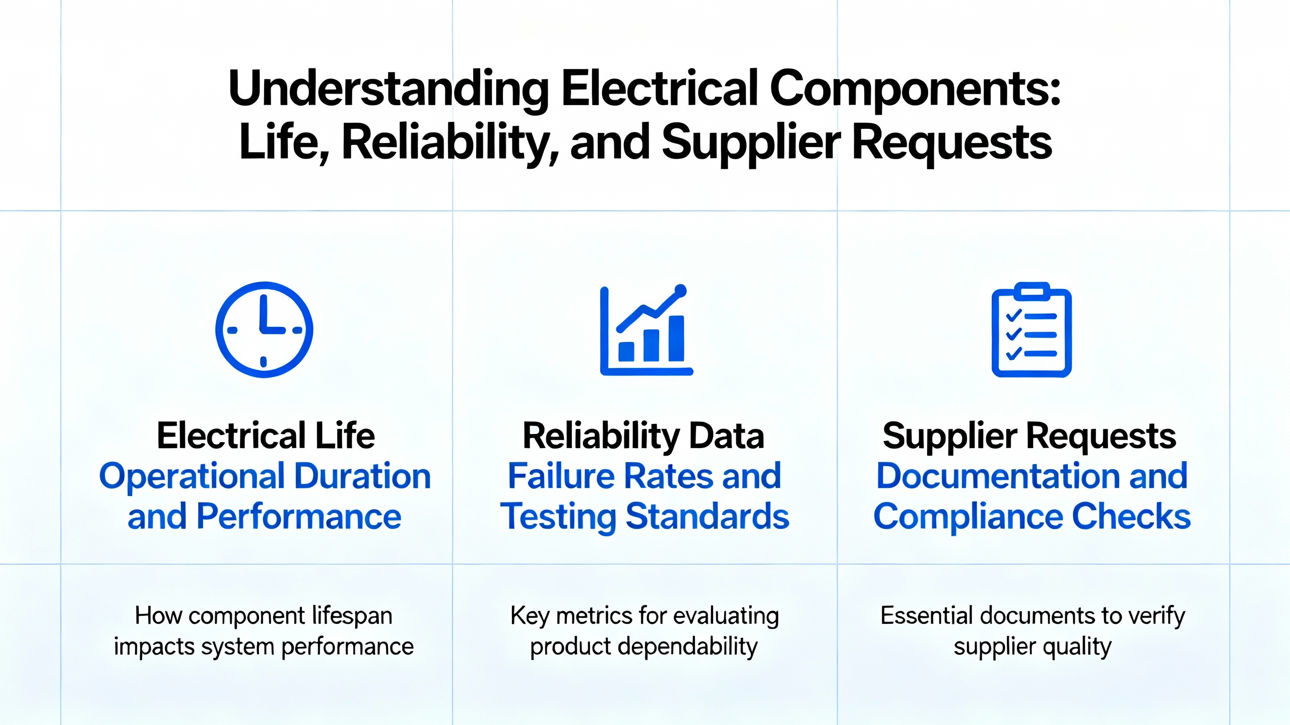
Electrical life, reliability data, and what to request from your supplier
When a failure triggers a reliability deep dive, asking the right questions helps Schneider and authorized suppliers support you quickly. The Schneider Electric Community has discussed the types of evidence buyers and safety engineers should request. There is value in typeŌĆætest reports to IEC 60947ŌĆæ4ŌĆæ1, endurance test data, and the functionalŌĆæsafety metrics that many organizations use, including FMEDA, B10d, and MTBF figures. Reliability engineers should also confirm application derating limits for ambient temperature and altitude and check that the utilization category aligns with the duty. For shortŌĆæcircuit performance, request details about prospective fault level, the backŌĆæup protection used in testing, and whether the published rating reflects worstŌĆæcase across a frame size or only the maximum frame.
Academic work on contactor electrical life supports practical modeling. An analysis available through Academia.edu reports that electrical life under controlled dispersion tends to follow a Weibull distribution, consistent with IEC practice, while high manufacturing dispersion can push behavior toward a normal distribution. For reliability calculations, this implies that you should validate the assumed life distribution with supplier data and account for manufacturing variability across batches rather than assuming a oneŌĆæsizeŌĆæfitsŌĆæall shape parameter.
Authorized supplier choice matters. Balaji Switchgears emphasizes that authorized Schneider providers deliver genuine parts, application guidance, afterŌĆæsales support, training, and warranty alignment with SchneiderŌĆÖs global standards. In my experience, that also translates into faster access to typeŌĆætest reports and clear guidance on coordination and derating.
Preventive maintenance and care for contact longevity
Effective preventive maintenance of Schneider contactors is not glamorous, but it is remarkably costŌĆæeffective. Regular inspections should look for burn marks and discoloration, retorque terminals that loosen under vibration and thermal cycling, and clear dust or debris using OEMŌĆæapproved methods. Balaji Switchgears specifically advises avoiding abrasives on contacts, and that matches my inŌĆæhouse policy; aggressive abrasion removes plating and accelerates wear. Measure coil resistance during scheduled outages and trend results, because subtle shifts foreshadow degradation. Watch temperatures; if a cabinet cannot hold the local air near the contactor at the recommended limit, add circulation fans or ventilation and confirm improvement. Operate the device under actual load during PM, listen for unusual noise or delay in pullŌĆæin, and investigate anomalies rather than normalizing them. Finish every maintenance window by updating the log; over time, patterns reveal bearings starting to drag or control supplies drifting out of tolerance.
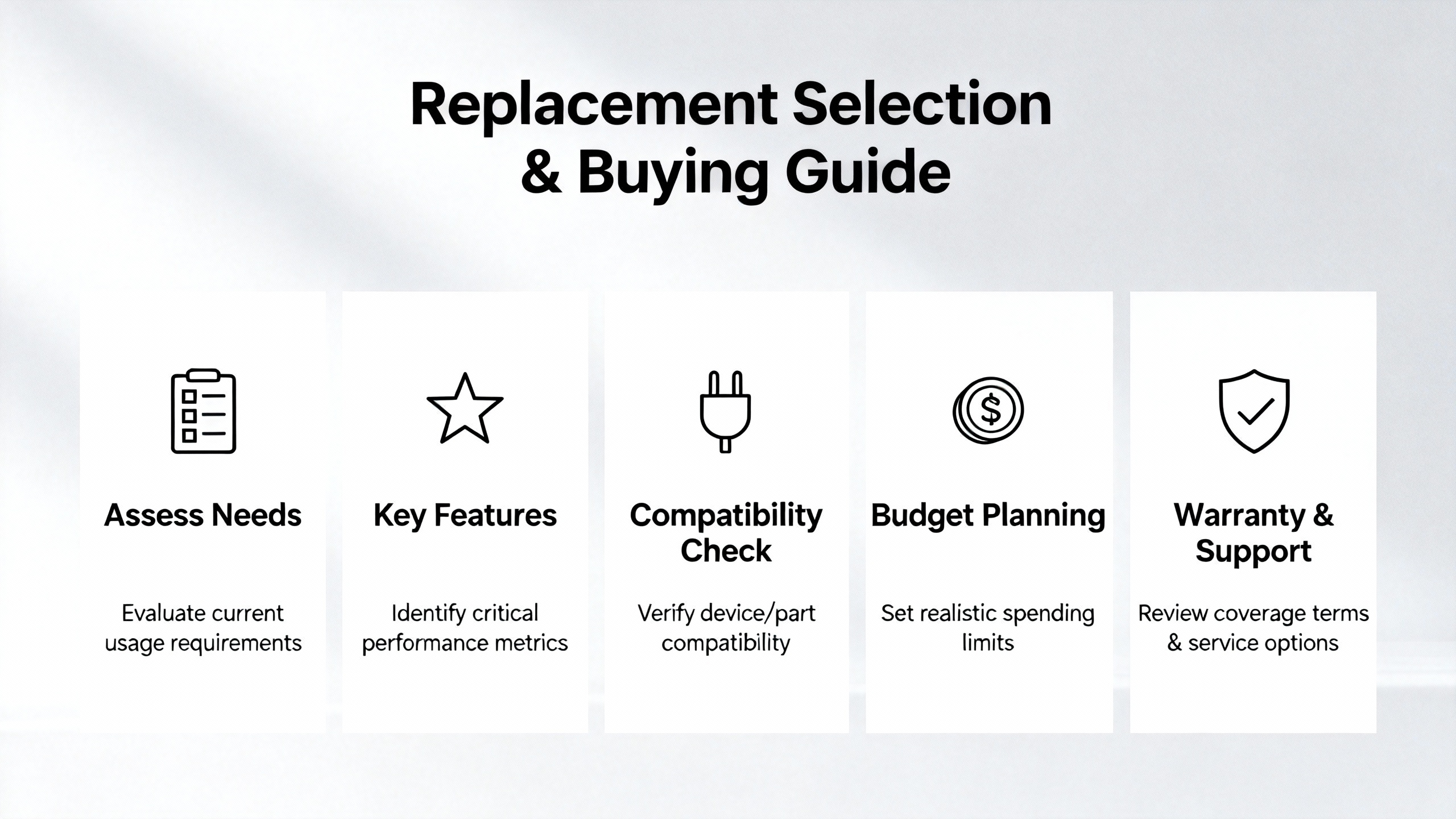
Selection and buying guidance when replacement is necessary
Most emergency replacements succeed, but many miss opportunities to improve resilience. A concise checklist, verified with your Schneider distributor, avoids repeat failures and compliance headaches.
| Buying consideration | Why it matters | How to verify before purchase |
| Utilization category and duty (for example, ACŌĆæ3 versus ACŌĆæ4) | Arcing energy per operation varies by duty; misapplication erodes contacts early | Match duty to the actual load profile using Schneider data and the controller manual |
| Coil voltage and tolerance | Control undervoltage or overvoltage accelerates coil and contact damage; regional mains matter | Read the nameplate; confirm supply stability; consider coil selection matched to local supply as Schneider Electric advises in regional FAQs |
| Ambient temperature inside enclosure | Coil life depends on air adjacent to the device, not cabinet nameplate | Measure hotspots; ensure air local to the contactor stays near 140┬░F or lower; plan for fans if needed |
| ShortŌĆæcircuit and overload coordination | Limiting letŌĆæthrough energy protects contacts and motors | Confirm IEC 60947ŌĆæ4ŌĆæ1 coordination type and the approved breaker/fuse pairings in Schneider documentation |
| Auxiliary contact requirements | Control and safety feedback correctness relies on proper aux logic | Specify needed NO/NC combinations and mechanical interlocks; verify in schematics |
| Authorized source and documentation | Genuine parts, warranty, and application support reduce risk | Buy from authorized Schneider partners; request typeŌĆætest and endurance data when needed |
A final wiring and protection note improves outcomes disproportionately. In singleŌĆæphase starters, ensure the overload relay sees current through all three sensors by looping the appropriate phase. Practitioners repeatedly discover this omission during nuisance trips. Also scrutinize the upstream breaker type and listing for the controller; follow the starter manufacturerŌĆÖs instructions and applicable code requirements, as highlighted in professional forum case studies.
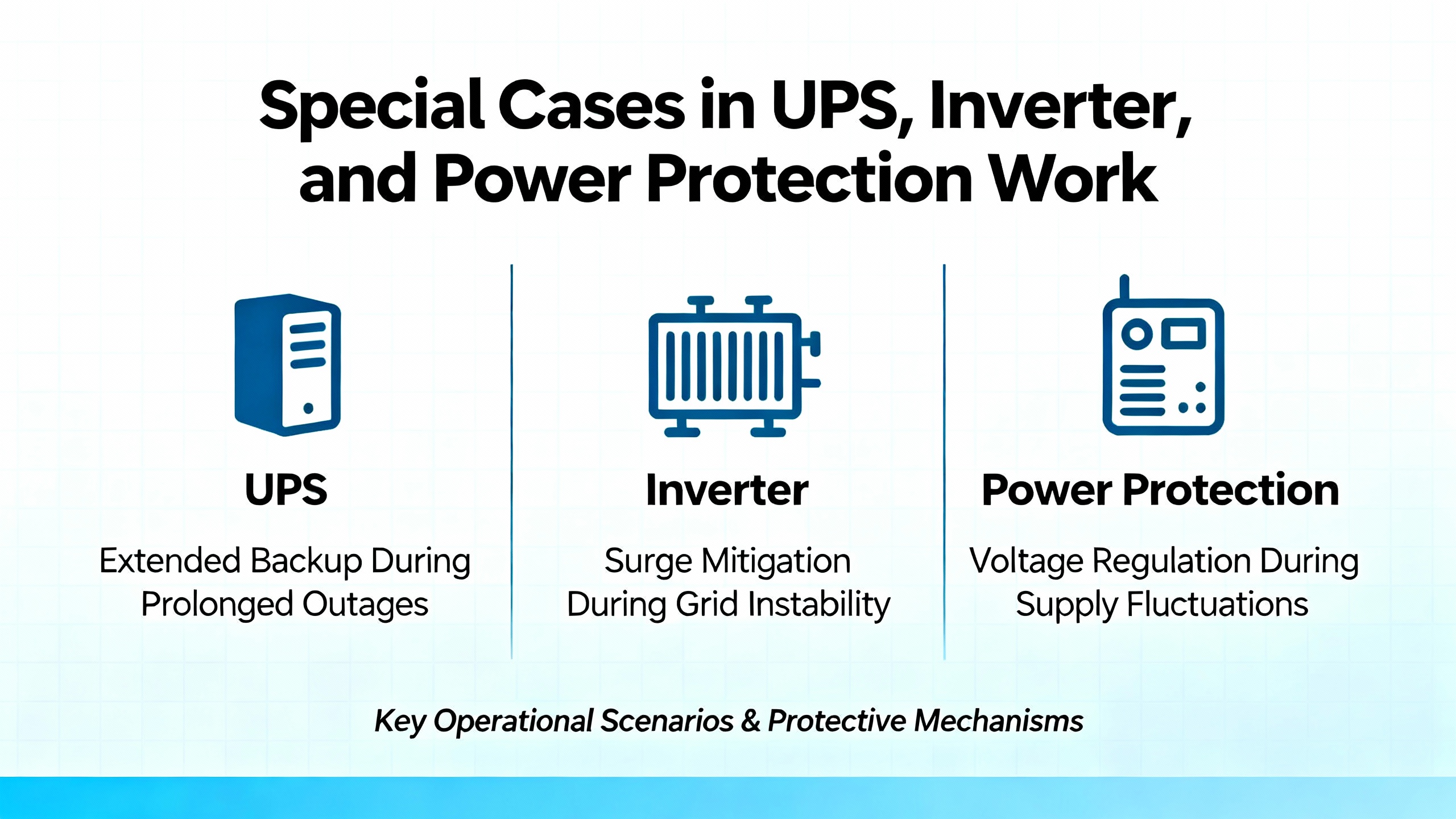
Special cases in UPS, inverter, and power protection work
In UPS static bypass cabinets and inverter output switchboards, seemingly minor contactor imperfections amplify into significant events. Frequent switching during transfers and synchronizations magnifies arc wear. Control supplies for coils sometimes come from the UPS auxiliary bus or a DC/DC converter, which can run close to their limits under heat, creating undervoltage at exactly the wrong moment. In these contexts, ensure control wiring has generous margins and that coil selections match the actual auxiliary supply. When UPS or inverter vendors recommend specific Schneider contactor part numbers with defined coordination and coil ratings, follow them exactly, and ask for the associated typeŌĆætest references if reliability verification is on your scope.
Takeaway
Electrical contact failure in Schneider contactors is solvable, predictable, and preventable when you treat symptoms as signals rather than outcomes. The fastest route to stable operation starts with safe, methodical diagnosis; verifies control voltage and sealing behavior; confirms protection and duty; and addresses the environment the device actually lives in. Supplier data makes decisions easier when you request the right artifacts, and disciplined preventive maintenance locks in the gains.
FAQ
Why do coils keep burning out if they are ŌĆ£continuous dutyŌĆØ coils?
Coils are designed for continuous service, but only when the armature seals fully and air temperature near the device stays within limits. Undervoltage, contamination on mating faces, and mechanical obstruction prevent sealing, so the coil draws higher current and overheats. Schneider Electric guidance emphasizes keeping local air near the contactor around 140┬░F and ensuring the armature seats cleanly; even modest overvoltage can become destructive if temperature is already high.
Is contactor humming always a sign of failure?
Some hum in AC contactors is normal, but a loud or new buzz indicates a weak magnetic hold or resonance. Undervoltage, phase imbalance, contaminated pole faces, or a degraded shading coil are common culprits. Measure coil voltage during pullŌĆæin, clean and inspect mating faces, and replace the coil or contactor if the shading ring is damaged, as described in manufacturer notes and independent engineering articles.
Can I sand or file burnt contacts to extend life?
It is not recommended to abrade contact faces. OEMs and maintenance advisors such as Balaji Switchgears advise against abrasives because they remove protective plating and can embed debris, which increases resistance and accelerates wear. Clean gently with approved methods and replace worn or pitted contacts or the entire contactor as specified by Schneider.
How do I tell if the contactor or the motor is at fault?
Test both the control and power sides. If coil voltage and resistance are correct and contact resistance is reasonable yet the motor still misbehaves, inspect the motor branch. A grounded motor or imbalanced windings will draw abnormal current and can weld contacts or trip protection. BIN95ŌĆÖs workflow of megging to ground, comparing phase resistances, and checking current symmetry cleanly separates motor faults from switching faults.
What reliability data should I ask for if a failure prompts a review?
Request IEC 60947ŌĆæ4ŌĆæ1 typeŌĆætest documentation, endurance data, and if your process requires it, FMEDA, B10d, and MTBF figures. Clarify derating limits for ambient temperature and altitude and verify utilization category against the real duty. On shortŌĆæcircuit performance, ask how ratings were established and with which backŌĆæup protective devices, as discussed in Schneider ElectricŌĆÖs community forums.
How often should I retorque terminals and inspect contacts?
Intervals depend on duty and environment, but the principle is consistent across sources like Balaji Switchgears, Control.com, and NTT Training: schedule regular inspections, retorque as per Schneider recommendations to counteract vibration and thermal cycling, and trend coil and contact resistance. Logs are your friend; they reveal drift before it becomes downtime.
References
- https://www.academia.edu/118989297/Analysis_of_Electrical_Life_Distribution_Characteristics_of_AC_Contactor_Based_on_Performance_Degradation
- https://dspace.mit.edu/bitstream/handle/1721.1/117970/1051237892-MIT.pdf?sequence=1&isAllowed=y
- https://eng.najah.edu/media/filer_public/d7/95/d795b1d9-e4de-41d2-9b84-2bd3c3ed4ca0/control_lab_manual.pdf
- https://www.geya.net/contactor-testing-guide/
- https://www.ato.com/contactor-troubleshooting-guide?srsltid=AfmBOoraxyyRKkaqhK7QH-pFjXQMsN9QMsP4vGy72C2sZVXB2IgCVc5G
- https://balajiswitchgears.com/maintenance-tips-for-schneider-contactors/
- https://forum.allaboutcircuits.com/threads/problems-with-contactors-burning-out.131687/
- https://bin95.com/articles/electrical/electrical-industrial-troubleshooting.htm
- https://control.com/technical-articles/tricks-of-the-trade-troubleshooting-industrial-control-cabinets/
- https://www.delair.com/blog/signs-ac-contactor-failure/


 Videos
 News
News Applications


Leave Your Comment