When a Schneider Altivar variable frequency drive refuses to start, operations stall, checks multiply, and pressure mounts. As a power system specialist who has commissioned, troubleshot, and lifeŌĆæcycled hundreds of drives across manufacturing, water, and building systems, IŌĆÖve learned that most ŌĆ£wonŌĆÖt startŌĆØ events fall into a handful of recurring patterns. The good news is that these patterns are diagnosable and solvable if you understand what the display is telling you, how Altivar control modes behave, and where environment and power quality quietly sabotage startups. This guide distills field experience with Altivar families such as ATV12, ATV21/212, ATV31/312/320, and ATV58/61/71, reinforced by best practice from reputable sources including ACS Industrial, Tommy Car Wash Systems, EEPower, Control Engineering, Schneider Electric FAQs, and peerŌĆæreviewed troubleshooting frameworks.
What ŌĆ£Startup FailureŌĆØ Means on Altivar Drives
Not every nonŌĆærunning drive is in a fault state. Altivar front panels distinguish three states that feel like ŌĆ£wonŌĆÖt startŌĆØ to operators. The first is dead, where the display is blank because input or control power is missing. The second is disabled, where the drive is healthy but not permitted to run because of its status or interlock logic. The third is faulted, where the drive latched a protective trip.
A frequent confusion point on the ATV310 is the panel showing ŌĆ£--06.ŌĆØ That code is a status, not a fault. It means freewheel stop, sometimes called freeŌĆærun stop, where output is inhibited by design and the motor is allowed to coast. Until the freewheel condition is cleared, the drive will ignore run and speed commands. I have seen this status repeatedly after a control logic change or miswired start circuit. The most common root cause is a digital input mapped to freewheel that is still asserted, although a missing analog reference or a host that does not send a valid run bit over Modbus can create the same effect. In normal conditions, a ready status will appear as ŌĆ£--00ŌĆØ or ŌĆ£rdY,ŌĆØ and the drive will accept a run command and generate frequency.
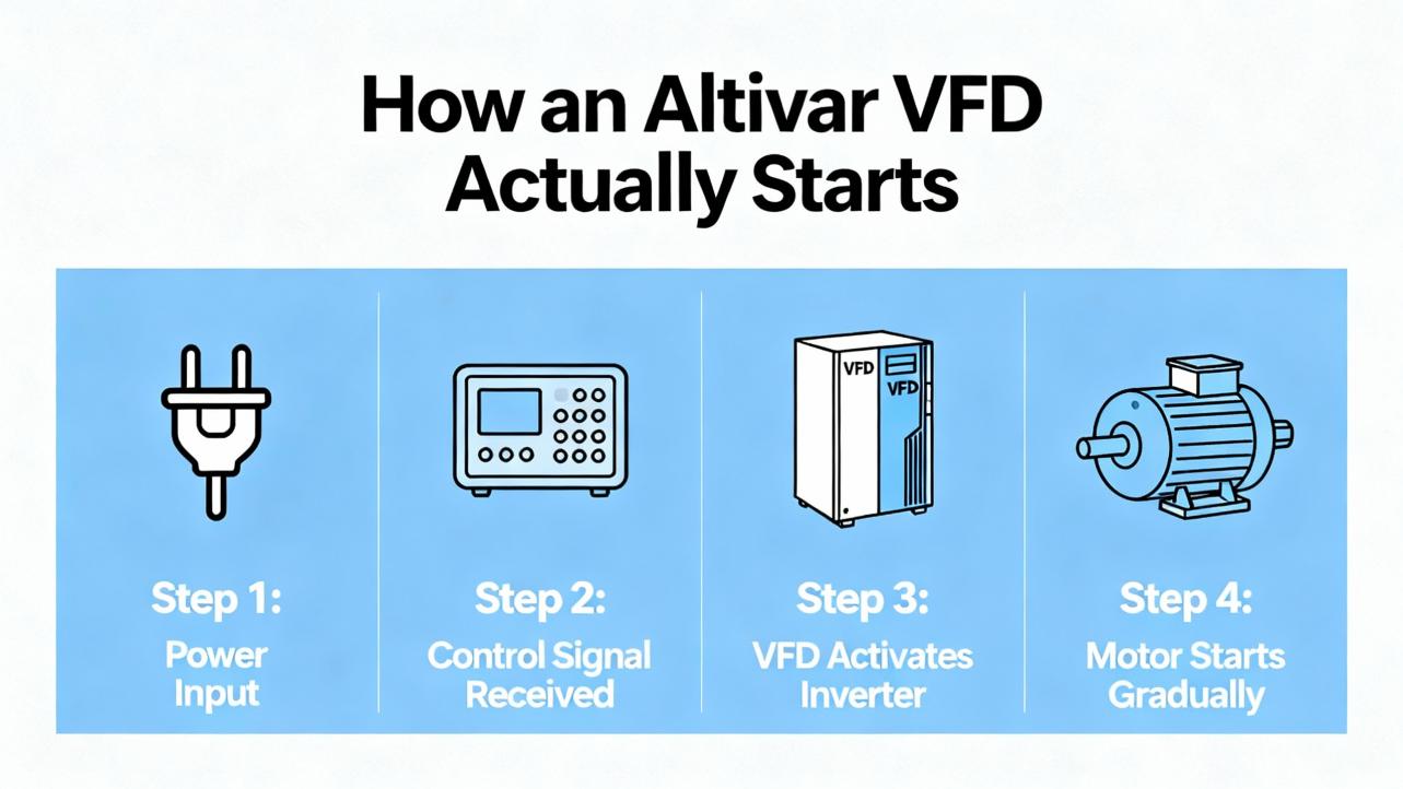
How an Altivar VFD Actually Starts
A quick primer helps avoid chasing the wrong thing. A VFD rectifies AC line power to a DC bus on large electrolytic capacitors and then inverts that bus into a variableŌĆæfrequency, variableŌĆævoltage AC waveform using IGBTs. The control section needs two things to start the motor: a run command and a speed reference. On Altivar, the command can come from digital inputs, a keypad, or a fieldbus; the speed can come from the keypad, an analog input such as 4ŌĆō20 mA, or a network register. Control methods range from basic voltsŌĆæperŌĆæhertz to selfŌĆæsensing vector and closedŌĆæloop vector with an encoder. The driveŌĆÖs thermal model relies on a correct motor fullŌĆæload amp value and appropriate acceleration and deceleration times. Most Altivars are rated for ambient operation up to about 104┬░F; above that, derating applies, and enclosure cooling becomes mission critical. The interplay of command source, speed source, and environment explains why ŌĆ£nothing happensŌĆØ is often a configuration or conditions issue, not a failed power section.
Fast Triage: Dead, Disabled, or Faulted
The fastest path to recovery is to decide which bucket you are in. If the panel is off, verify incoming AC and any separate control power supplies first, then remain disciplined with lockout/tagout and capacitor discharge waiting periods before opening covers. ReŌĆæenergizing repeatedly into a suspected shorted rectifier is dangerous and can escalate damage. A few minutes spent with a true RMS meter at the line terminals and a nonŌĆæpowered diode test across the rectifier prevents explosive resets that blow fuses and buckets; this practice matches the practical advice shared by veteran troubleshooters on the Mike Holt Forum.
If the panel is on and shows ŌĆ£rdYŌĆØ or ŌĆ£--06ŌĆØ but the motor is not responding, concentrate on the command chain. On ATV310 and related models, the control mode determines whether the run signal must be maintained level (twoŌĆæwire) or pulsed (threeŌĆæwire). I often see twoŌĆæwire mode configured while a PLC issues a oneŌĆæshot, which leaves the drive permanently stopped. It is also common for a freewheel function to be mapped to a digital input that someone tied high during commissioning and never released. The fix is usually to confirm the control mode, reassign unused inputs to ŌĆ£No Function,ŌĆØ and watch the live I/O status on the HMI monitor pages to see whether the drive is actually seeing the run, stop, and speed signals.
If the drive is faulted, treat the trip code as a clue and not a verdict. Codes such as SLF/SLF1, OBF, OPF/OPF1/OPF2/EPHO, and OCF/OCA/EF2 show up frequently at or near startup in Altivar fleets documented by Tommy Car Wash Systems, and every one of those codes maps to a short, actionable set of causes and corrections when interpreted in context.

Common Altivar Startup Failure Patterns and Fixes
Communication and control path issues are commonplace in networked installations. SLF or SLF1 indicates a communication error that often clears with a controlled power cycle. If it returns, verify the physical layer first, including the RJ45 lead, termination, and the Modbus router or switch. In my experience, you want to confirm that the host PLC is truly enabling the run bit and writing a nonzero speed reference, because a healthy bus and a silent host look the same as a broken cable to the drive. That observation lines up with field notes from Tommy Car Wash Systems and typical VFD troubleshooting flowcharts from Do Supply.
DC bus overvoltage on deceleration, identified by OBF, can appear at first run when a stopped process is commanded to halt aggressively after a quick test jog. The energy pumped back from a high inertia load elevates the DC bus faster than the chopper can sink it. Increasing deceleration time is the primary correction, and on processes that genuinely require fast stops, the remedy is to add a dynamic braking resistor or a regenerative unit sized to the inertia. If OBF persists even with conservative decel, verify that the incoming line voltage is within tolerance because a high utility line elevates the bus from the start; ACS Industrial and EEPower both emphasize that ŌĆ£high busŌĆØ faults result from either supply spikes or overhauling loads.
Output phase not connected appears as OPF, OPF1, OPF2, or EPHO depending on the family. At startup this usually means a downstream disconnect is open or a motor lead is loose enough to arc under load. When it shows up in a carŌĆæwash conveyor or a pump skid, I read it as a wiring problem until proven otherwise. Corrective action is straightforward: close the disconnect and torque the terminals to specification. Do not ignore the risk of damaged insulation from repeated arcing, and inspect the motor junction box for carbon tracks and debris.
Overcurrent and ground faults such as OCF, OCA, and EF2 are the most common trips right as motion begins. Pumps that start with clogged nozzles or air bound piping pull surges well above the programmed limits, and conveyors with a stalled section or foreign material behave the same way. The fix begins mechanically by clearing the load, and electrically by easing acceleration, checking for low input voltage, and confirming the motorŌĆÖs fullŌĆæload amp value in the parameters. If the fault returns, separate the system into the drive, the motor cable, and the motor. With power removed and properly discharged, megger the motor and cable, but never megger the VFD power section; this is a proven best practice taught by Precision Electric and echoed by Do SupplyŌĆÖs troubleshooting guidance.
FrontŌĆæend rectifier failure is a special case. Two clues converge: a drive that takes out its input fuses and even the upstream breaker, and a loud bang on reŌĆæenergization. At that point, assume the input diodes or transistors are shorted. Do not attempt to ŌĆ£testŌĆØ by energizing again; instead, confirm with a nonŌĆæpowered diode test and replace the unit or send it for repair. Surge protective devices are valuable but not omnipotent on large industrial buses. On drives that live in harsh switching environments, adding a line reactor to slow di/dt transients is a reliable mitigation, a practice recommended by seasoned electricians dissecting these failures in Mike HoltŌĆÖs community.
Environment and Power Quality Root Causes that Block a Clean Start
The ŌĆ£electronic axis of evilŌĆØ for drives is dirt, heat, and moisture. That phrase, used by ACS Industrial, summarizes what I see in the field. Dust mixed with oil becomes conductive, blocks vents, and creates stray current paths on boards. Moisture condenses and accelerates corrosion, particularly in water and wastewater facilities, because cooling fans draw humid air across the printed circuit assemblies. Heat shortens component life, especially electrolytic capacitors on the DC bus that are the first to bulge and leak in an overheated panel. The fix is not heroic. Keep the cabinet clean and dry; blow out heatsinks and fans using dry, nonŌĆæstatic air; maintain filters; and match the enclosure to the environment, up to NEMA 4 or 4X for washŌĆædown areas or NEMA 12 for dusty indoor spaces. In very humid sites, I have seen 24/7 operation keep internals dry by maintaining cabinet temperature, a pragmatic trick noted by ACS Industrial and CM Industry Supply, but do not let that become an excuse to ignore dehumidification and seal integrity.
Power quality is the silent killer. Line dips and spikes, a weak phase on the supply, or neighboring equipment that slams large loads on and off all degrade startup stability. Simple checks with a true RMS meter and a portable logger can reveal undervoltage during acceleration or repeated DC bus spikes. When your plant has a history of surges, consider a combination of surge protective devices and line reactors. The SPD clamps the worst energy while the reactor limits the rate of rise that defeats suppressors. This layered approach resonates with the realŌĆæworld mitigation strategies shared by practitioners and is consistent with CM Industry SupplyŌĆÖs guidance on power quality.
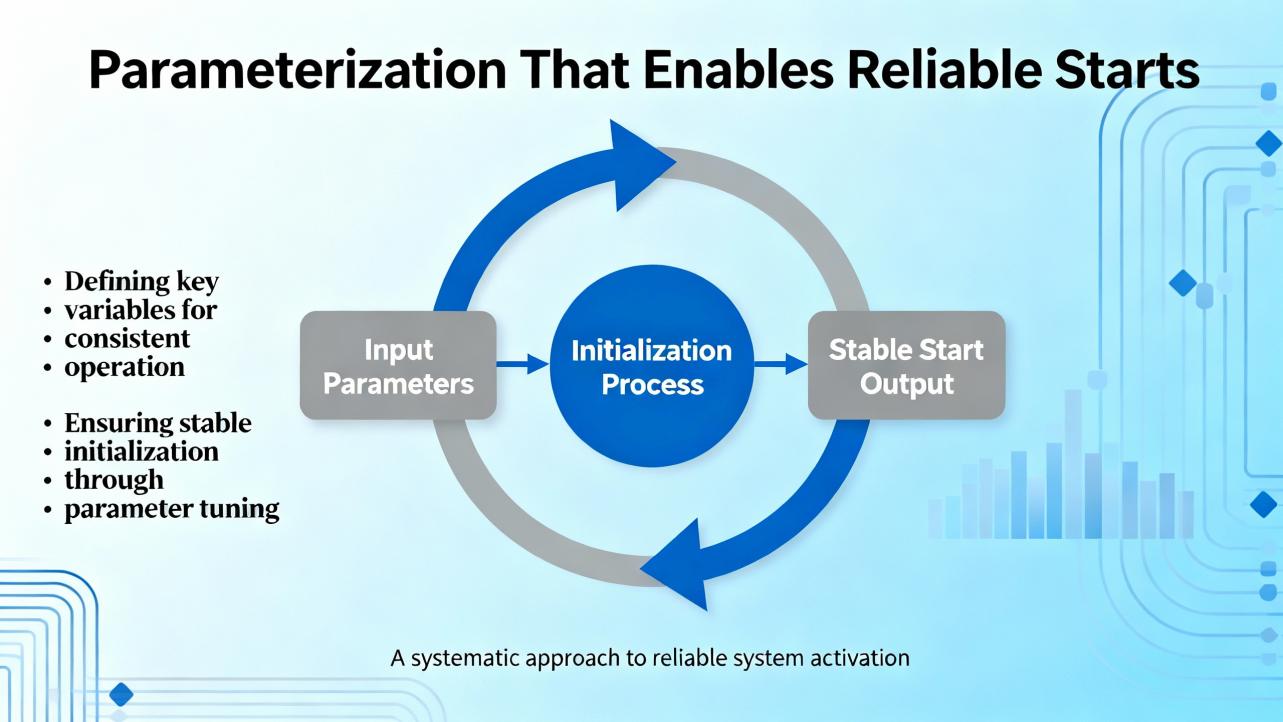
Parameterization That Enables Reliable Starts
Most applications need only a handful of settings to start predictably. Start by choosing the control method appropriate to the load, whether voltsŌĆæperŌĆæhertz for simple fans and pumps, selfŌĆæsensing vector for tighter torque control, or closedŌĆæloop vector for precision. Then program the motor fullŌĆæload amps straight from the nameplate so the electronic thermal model can do its job, an approach emphasized by Control Engineering for both safety and performance. Choose acceleration and deceleration times that respect the loadŌĆÖs inertia and the powertrainŌĆÖs current limits, and consider SŌĆæcurve ramps to soften mechanical shocks. Finally, confirm where the run and speed commands come from and test the actual signals using the live monitoring pages on the HMI. None of these steps is exotic, but aligning them prevents most nuisance nonŌĆæstarts that look like electronics but are simply misparameterized control chains.
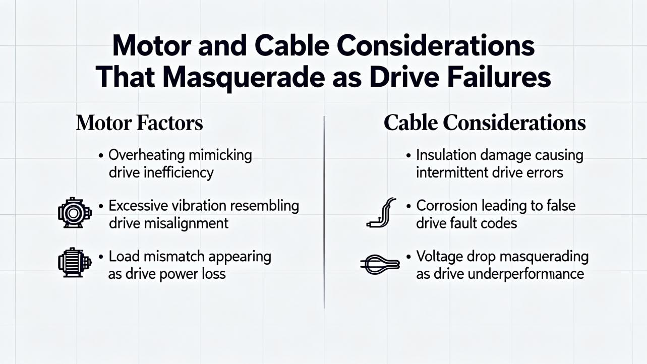
Motor and Cable Considerations That Masquerade as Drive Failures
A VFDŌĆÖs harsh PWM output creates high dv/dt at the motor terminals, especially with long leads. That reality makes cable selection and grounding matter. Use VFDŌĆærated shielded motor cable with low capacitance and 360ŌĆædegree shield terminations at both ends. Keep runs as short as practical, and if you must run long, add a dv/dt or sineŌĆæwave filter. On older motors not rated for inverter service, reflections can elevate terminal voltage to damaging levels, and poor grounding lets commonŌĆæmode currents find bearing paths. Schneider ElectricŌĆÖs own guidance on motor bearing failures points to shaft voltage discharges as a root cause of fluting; shaft grounding rings at the drive end combined with an insulated bearing at the nonŌĆædrive end form an effective protection scheme. You can also lower the carrier frequency when the process tolerates it to reduce highŌĆæfrequency stress. In my experience, addressing cables, filters, grounding, and bearing paths transforms ŌĆ£mystery tripsŌĆØ at start into a wellŌĆæbehaved system without touching the drive power section.
Preventive Maintenance and Documentation Habits
Preventive care is not glamorous, but it is cheaper than downtime. Keep a maintenance log of terminal torques, fan condition, and filter changes. Trend ambient and heatsink temperatures; when you see a rise with no load change, plan a cleaning shutdown. Replace fans that chirp or stall, and treat capacitors as wear items that age faster with heat and frequent cycling. Keep firmware current per manufacturer guidance, but change only one thing at a time and record it, a discipline recommended by CM Industry Supply and Joliet Technologies. Before removing a drive for analysis, export the fault and event logs and save the parameter set. Those records become evidence in a rootŌĆæcause analysis and shorten the path to a permanent fix.
Quick Reference: Typical Altivar Codes Seen at Startup
The following table summarizes codes that appear commonly when an Altivar refuses to run and ties them to the first checks that resolve most cases quickly. The ŌĆ£Status vs FaultŌĆØ column clarifies whether the code is a permissive state or a protective trip.
| Code or Status | Status vs Fault | What It Means at Startup | Likely Cause | First Actions |
| --06 | Status (no fault) | Freewheel stop; output inhibited | Digital input mapped to freewheel asserted; wrong twoŌĆæwire vs threeŌĆæwire mode; missing analog reference; host not sending run | Confirm control mode; watch live I/O; unmap or release freewheel input; verify run bit and speed reference |
| SLF / SLF1 | Fault | Communication error; no valid commands | Power cycle left bus in error; bad RJ45 or router; silent PLC | Power cycle once; inspect cable and router; confirm host writes run and speed |
| OBF | Fault | DC bus overvoltage on decel | Decel set too aggressive; high line voltage; high inertia with no braking path | Lengthen decel; measure line volts; add braking resistor or regen unit |
| OPF / OPF1 / OPF2 / EPHO | Fault | Output phase open | Downstream disconnect open; loose or damaged motor leads | Close disconnect; torque terminals; inspect junction box and cable |
| OCF / OCA / EF2 | Fault | Overcurrent or ground fault | Mechanical jam; airŌĆæbound or clogged pump; failing motor; shorted lead | Clear load; ease accel; verify motor FLA; megger motor and cable with drive isolated; never megger the VFD |
This mapping aligns with field documentation from Tommy Car Wash Systems and broad VFD troubleshooting practice taught by Do Supply and EEPower.
Sizing, Accessories, and Buying Tips for Fresh Installations
If your Altivar repeatedly refuses to start a demanding load, you may be trying to do the right job with the wrong rating or accessories. Drives carry dual duty ratings for variable torque and heavy duty. A unit that easily starts a fan may overload on a press or mixer that needs higher starting torque or longer accel. Match the driveŌĆÖs continuous amp rating to the motor nameplate and the duty profile, and allow current headroom for the actual process, not just horsepower. Size enclosure cooling realistically; a drive sheds a few percent of output power as heat, so a 30 hp class unit can add roughly 500 W to a sealed panel. For outdoor or washŌĆædown applications, choose NEMA 4/4X enclosures and plan for sun shielding.
Power quality and cable lengths dictate accessories at purchase. Where utility quality is poor or large contactors switch nearby, add a line reactor. For long motor leads, plan a dv/dt or sine filter and use true VFDŌĆærated cable to limit reflected wave stress. When you must stop quickly or hold a setpoint on a highŌĆæinertia system, include a braking chopper and resistor or a regen package. Budget for shaft grounding rings on motors that do not ship with them, and specify inverterŌĆæduty motors that meet modern standards to protect against insulation and bearing damage. These purchases are insurance against the very startup headaches that interrupt commissioning week.
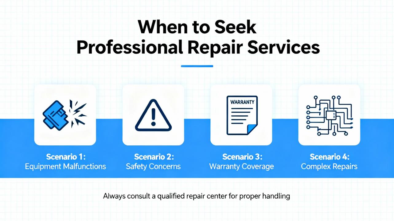
When to Involve Schneider Electric or a Qualified Repair Center
There is a point where field diagnosis should give way to a formal failure analysis. If the drive blew its input fuses and the breaker together, if a diode test shows a shorted rectifier, or if the unit trips on a hardware fault with no external cause, contact Schneider Electric support, collect the model and serial number, capture event logs and parameters, photograph the wiring and environment, and request an RMA. In warranty cases, the OEM route is usually fastest to a definitive root cause. In outŌĆæofŌĆæwarranty cases, reputable repair houses such as those profiled by ACS Industrial can provide a free evaluation and a partsŌĆæandŌĆælabor warranty on repairs. When production is at risk, a Schneider field service visit in parallel with a factory analysis keeps momentum while the lab work proceeds.
Safety Notes You Should Never Skip
Basic safety discipline prevents injuries and secondary damage. Always deŌĆæenergize, lock out, wait for DC bus capacitors to discharge, and verify absence of voltage before touching terminals. Never megger a VFD power section; perform insulation tests on the motor and cables only with the drive disconnected. Do not ŌĆ£proveŌĆØ a suspected frontŌĆæend short by cycling power; that approach can turn a repairable unit into shrapnel and a recordable incident. Use an infrared thermometer or pyrometer for hotŌĆæspot checks on lugs rather than blanket reŌĆætorquing; the latter can mask the real issue. These messages are consistent with Schneider ElectricŌĆÖs safety communications and the practical experience shared by UpFix and Do Supply.

Takeaway
Altivar startup failures almost always reduce to a few themes. Drives that are healthy but disabled display statuses like ŌĆ£--06ŌĆØ because their control logic is not aligned with how the system is wired. Drives that trip at start are often reacting to mechanical binding, aggressive ramps, or wiring faults, not a failed inverter stack. True power stage failures leave distinct fingerprints in fuses, breakers, and diode tests and call for structured analysis or replacement. Before swapping boxes, read the code, trace the command and speed path, clean and cool the enclosure, and stabilize the supply. Then correct the parameters, add the accessories that the application truly needs, and document the whole chain. That systematic approach is faster than guesswork, safer than trialŌĆæandŌĆæerror resets, and more reliable than treating symptoms.
FAQ
How do I clear ŌĆ£--06ŌĆØ on an ATV310 when the motor wonŌĆÖt start?
ŌĆ£--06ŌĆØ is a freewheel stop status that holds output off until the condition is cleared. Confirm whether the drive is configured for twoŌĆæwire or threeŌĆæwire control and verify that the correct run signal is present for that mode. Check whether any digital input is mapped to freewheel and still asserted, and look at the HMI I/O monitor to confirm what the drive is actually seeing. If control is via Modbus, make sure the host is sending a valid run bit and a nonzero speed reference. If in doubt, reassign unused inputs to ŌĆ£No Function,ŌĆØ release the freewheel signal, and return the status to ŌĆ£rdY.ŌĆØ
Why does my Altivar trip OBF as soon as I try to stop after a test run?
OBF indicates the DC bus rose too high during deceleration. The usual culprit is a decel time that is too short for the load inertia, especially on fans, conveyors, and centrifuges. Increase the decel time and test again. If the process needs quick stops, add a braking resistor and chopper or a regen unit. Also verify that the incoming line voltage is within specifications; a high supply reduces bus headroom and makes OBF more likely.
What should I check first for OCF or EF2 right at startup?
Start with the mechanics and the wiring. Clear any obstructions in pumps, fans, or conveyors and verify that bearings turn freely. Ease the acceleration ramp and confirm that the motor fullŌĆæload amps are programmed correctly. Then isolate the segments to test. With power removed, megger the motor and cable separately and check for low insulation resistance, but never megger the VFD. If the fault persists with the motor disconnected, suspect the drive. If it clears, suspect the motor or cable.
The drive blew fuses and tripped the breaker when I energized it. Can I try again?
Do not. A shorted frontŌĆæend rectifier often exhibits exactly that behavior. ReŌĆæenergizing into a solid short risks further damage and personal injury. Instead, deŌĆæenergize, verify absence of voltage, and use a nonŌĆæpowered diode test across the input rectifier to confirm. Replace the drive or send it for repair and consider adding a line reactor and surge protection if your site has transient events.
How do I prevent bearing failures on VFD motors running from Altivar drives?
PulseŌĆæwidth modulation introduces commonŌĆæmode voltage that can discharge through bearings, causing pitting and fluting. Use VFDŌĆærated, shielded motor cables with proper 360ŌĆædegree terminations and robust grounding. For additional protection, install a shaft grounding ring at the drive end and an insulated or ceramic bearing at the nonŌĆædrive end. Where possible, reduce the carrier frequency and keep motor leads short, or add a dv/dt or sineŌĆæwave filter on long runs. These mitigations align with Schneider ElectricŌĆÖs motor bearing guidance.
When should I call Schneider Electric for failure analysis?
If you suspect a hardware failure, especially after a severe trip or a power event, or if repeated corrective actions do not resolve trips, contact Schneider Electric support. Gather the model and serial number, export the fault and event logs, save the parameter set, and document the environment, wiring, and recent changes. In warranty, factory analysis accelerates a clean resolution. Out of warranty, reputable repair centers can provide evidenceŌĆæbased repairs and warranties.
By recognizing the difference between status and fault, aligning command logic with control modes, cleaning and cooling the environment, and addressing power quality and cabling, you turn ŌĆ£Schneider VFD not workingŌĆØ from a crisis into a routine recovery. For persistent or safetyŌĆæcritical cases, escalate with proper data to Schneider and lean on fieldŌĆætested practices from experienced technicians and reputable technical publishers.
References
- https://www.longi.net/troubleshooting-schneider-atv310-drive-displaying-06-and-failing-to-start-or-run/?srsltid=AfmBOopQ5HBWED3Jusq-FG2kcYuu6J3nSh1nk2kck9rrQJLTCgiMGRMJ
- https://www.researchgate.net/publication/265206532_Analysis_of_Electrical_and_Non-electrical_Causes_of_Variable_Frequency_Drive_Failures
- https://www.gohz.com/the-most-common-causes-of-vfd-failure?srsltid=AfmBOoo26WsOIJpNOx7JRbZ7OaS9uoN8gcPRyoR5ezyitRmiRNQbwl2p
- https://www.proxxi.co/case-study-schneider
- https://blog.upfix.com/what-causes-a-vfd-inverter-to-fail-expert-tips
- https://cmindustrysupply.com/blogs/preventing-vfd-faults-and-failures-a-comprehensive-guide
- https://www.controleng.com/top-5-vfd-parameter-changes-explained/
- https://drivefixelectronics.com/blog/the-impact-of-vfd-failures-on-industrial-operations-and-how-to-prevent-them
- https://blog.acsindustrial.com/variable-frequency-drive-repair/top-6-reasons-for-vfd-failure-and-how-to-prevent-them/
- https://eepower.com/technical-articles/motor-starters-part-8-variable-frequency-drive-failures/


 Videos
 News
News Applications


Leave Your Comment