Why Ethernet Failures Matter in Power-Critical Plants
When an AllenŌĆæBradley EtherNet/IP network goes dark, it is rarely ŌĆ£justŌĆØ a networking nuisance. In plants where PLCs coordinate UPS systems, inverters, switchgear, and power protection equipment, a lost Ethernet link can leave you blind to alarms, unable to transfer load, or stuck in manual mode on highŌĆævalue assets. I routinely see downtime events where the physical power system is healthy, but a failed Ethernet path between a ControlLogix or CompactLogix controller and its I/O or HMI brings production to a halt.
Public guidance from Rockwell Automation, RealPars, PLC Department, Industrial Automation Co., and others all converge on the same theme: most ŌĆ£Allen Bradley Ethernet not workingŌĆØ cases are traceable to fundamentals. Power, cabling, IP addressing, communication drivers, and firmware compatibility account for the vast majority of outages. Once those are under control, higherŌĆælevel issues like network overload, multicast flooding, or device limitations become easier to isolate.
This article lays out a practical restoration workflow grounded in those sources and in field experience with industrial and commercial power systems. The emphasis is on getting communications back quickly, then hardening the network so that the next utility dip, UPS switchover, or maintenance shutdown does not trigger another Ethernet surprise.
How AllenŌĆæBradley Ethernet Networks Are Built
Core components in a Logix Ethernet network
Across ControlLogix, CompactLogix, and other AllenŌĆæBradley families, the Ethernet side of the control system typically includes a processor, I/O modules, communication modules, and the supporting network infrastructure.
The processor, or CPU, executes the control logic written in tools such as RSLogix 5000 or Studio 5000 and coordinates communications with I/O, HMIs, and supervisory systems. Digital and analog I/O modules connect the controller to the real world: breaker position switches, voltage and current transducers, inverter status words, and trip contacts. Communication modules such as ENBT and EN2T provide the EtherNet/IP interface, often as plugŌĆæin modules within a Logix chassis.
Around this core, there are Ethernet switches and routers, HMIs, SCADA or MES servers, and sometimes OPC servers such as IgnitionŌĆÖs OPC UA server. As described by CT Robotics and by academic treatments of industrial networks, EtherNet/IP is one of several Common Industrial Protocol (CIP) networks alongside ControlNet and DeviceNet. EtherNet/IP gives you highŌĆæspeed Ethernet connectivity, while fieldbuses and backplane buses handle local, deterministic control where needed.
Where things go wrong
Ethernet problems hit at different levels. Industrial Automation Co. and PLC Department note that controllers may report I/O not responding, process HMIs may lose communication with the PLC, or engineering workstations simply cannot ŌĆ£go onlineŌĆØ with a controller over Ethernet. RealPars shows tools such as FactoryTalk Linx or RSLinx Classic failing to discover PLCs that are clearly powered up.
Rockwell Automation documentation and thirdŌĆæparty training guides also highlight how physical layer problems, misconfigured IP addresses, driver misŌĆæselection, firmware mismatches, and corrupted modules can each be enough to break the EtherNet/IP path. Network specialists on technical forums add another layer: misŌĆænegotiated duplex, Ethernet ŌĆ£spamming,ŌĆØ and poor multicast control can overload communication modules and cause intermittent or cascading failures.
Understanding which symptom you are facing usually points directly at the part of the stack that needs attention.
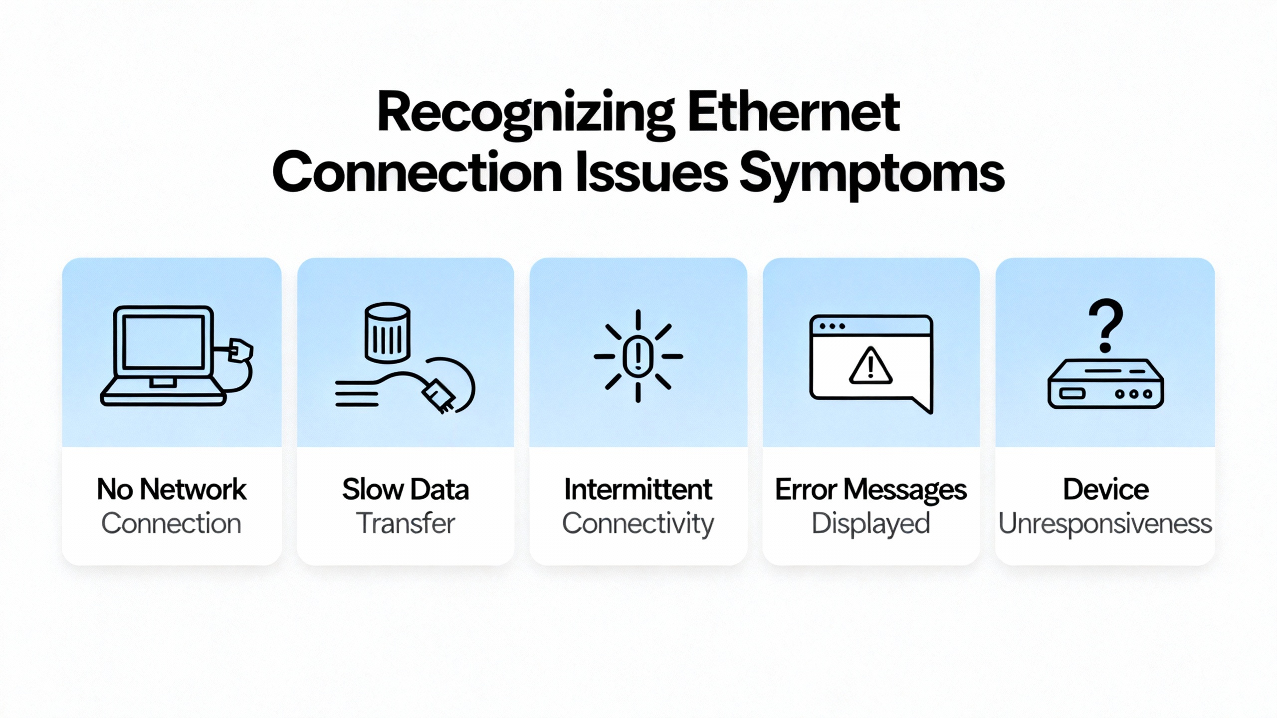
Recognizing ŌĆ£Allen Bradley Ethernet Not WorkingŌĆØ Symptoms
Top issue lists from Industrial Automation Co., PLC Department, and others consistently mention a few recurring signs.
One is the ŌĆ£I/O Not RespondingŌĆØ condition. This typically indicates that the controller has lost its EtherNet/IP I/O connection to one or more remote modules. Recommendations include checking wiring and module seating, confirming that the configured I/O matches the installed hardware, and power cycling the affected I/O or chassis.
Another is ŌĆ£No Communication with HMI or SCADA.ŌĆØ PLC Department reports that this is most often a network configuration issue: wrong IP address, subnet mask, or gateway, damaged Ethernet cables, or misconfigured communication drivers in software such as RSLinx.
RealPars highlights a common scenario in which FactoryTalk Linx or RSLinx cannot find the PLC over the EtherNet/IP driver. In their examples, the ŌĆ£Who ActiveŌĆØ or browse window shows stale entries with red X icons for devices that used to be reachable, and new devices never appear because discovery is not running on the correct network adapter or subnet.
Industrial Automation Co. and ACS Industrial also point to visible clues on the hardware. Flashing red LEDs on a communication or I/O module often indicate hardware faults or communication loss, while a power supply fault can show up as controller LEDs that never reach a solid healthy state. In ACS IndustrialŌĆÖs ControlLogix troubleshooting tips, a faulty Ethernet module is one of the root causes discovered after physical checks and diagnostic tool use.
A controller ŌĆ£Major FaultŌĆØ is another symptom often tied to communication or configuration errors. Industrial Automation Co. advises using RSLogix or Studio 5000 to read the fault code, clear it, reŌĆædownload a knownŌĆægood program, and ensure firmware compatibility between controller and modules.
These symptoms map to specific layers in the system, and treating them as such keeps troubleshooting organized rather than reactive.
A Structured Restoration Workflow
The fastest recoveries I see follow a repeatable pattern. Rather than jumping straight into program edits or swapping hardware at random, the effort moves from power and physical layer, to addressing, to driver configuration, to device health, and finally to networkŌĆæwide behavior.
Step 1: Verify power and the physical layer
Guides from RT Automation and Ethernet specialists emphasize that physical checks are the starting point. If the devices are not powered correctly or there is no valid Ethernet link, no amount of software tweaking will bring the network back.
Begin by confirming that all PLC chassis, Ethernet modules, switches, and industrial devices are powered and that their power supply indicators show normal status. Industrial Automation Co. notes that a ŌĆ£Power Supply FaultŌĆØ can destabilize PLC behavior and cause module resets and communication failures. They recommend checking for excessive load, fluctuating input voltage, aging or damaged supplies, and proper grounding and noise isolation. PLC Department similarly calls for verifying incoming supply voltage and inspecting UPS or battery backups as part of basic power troubleshooting.
This is where a powerŌĆæsystems mindset pays off. Verify that the UPS supplying the PLC rack and Ethernet switches is not overloaded, that its input source is stable, and that any recent transfer events did not leave downstream devices in an underŌĆævoltage or brownout state. Checking terminals and grounding against manufacturer guidance helps eliminate intermittent dips that can reboot Ethernet modules.
Once power is confirmed, focus on the Ethernet links. RT AutomationŌĆÖs Ethernet troubleshooting guide suggests examining Link and Activity LEDs on each port. A dark Link LED usually indicates no physical connection or a cable or connector fault. A Link LED that is on but with no Activity often points to dead traffic or a device that is not negotiating properly.
Check that the correct type of copper Ethernet cable is used and that terminations are sound. RT Automation distinguishes between straightŌĆæthrough cables for deviceŌĆætoŌĆæswitch connections and crossover cables for certain deviceŌĆætoŌĆædevice connections. Damaged conductors, bent RJŌĆæ45 pins, and untwisted pair terminations are common culprits in harsh environments.
For fiber connections, they advise verifying that the transmit and receive pairs are correctly crossed between devices and recognizing that older fiber runs can degrade over time. In older plants, I have found fibers that have simply aged out in terms of attenuation, making marginal links fail when environmental conditions change.
Physical distance also matters. Standard copper Ethernet runs are rated for about 330 ft. RT Automation notes that exceeding recommended distances can create intermittent performance and connectivity problems, especially when combined with electrical noise from large drives, transformers, or switchgear.
In electrically noisy environments, both RT Automation and contributors on MRPLC describe how automatic speed and duplex negotiation can fail. A device locked at 100 Mbps half duplex talking to a switch expecting full duplex can see high collision or error rates and very poor throughput. In some situations, deliberately forcing devices to a lower speed such as 10 Mbps with correct duplex has improved stability on marginal cabling, at the cost of peak throughput.
At the end of this step, you want solid Link/Activity LEDs on all critical connections, no obvious physical damage, and verified power quality feeding the PLC and networking devices.
Step 2: Confirm IP addressing and subnet configuration
With the physical layer stable, the next major source of ŌĆ£Ethernet not workingŌĆØ problems is IP configuration. Industrial Automation Co., My PLC Training, PLC Department, and RealPars all stress that PC and PLC must be on compatible IP addresses and subnets, and that duplicate IPs must be avoided.
Industrial Automation Co. explains that Windows PCs are often configured for DHCP by default, but to connect directly to AllenŌĆæBradley or CompactLogix EthernetŌĆæenabled controllers you typically configure a static IP address on the PCŌĆÖs network adapter. Their examples use Windows versions such as Windows 7 or XP, but the same principles apply in more recent systems.
My PLC Training walks through this in a Windows 10 context, describing how to set a static IP in the adapter properties so that the PC is in the same subnet as the PLC. They note that for a controller at an address ending in a particular octet, the PC can be given a different final octet within the same network segment, provided no two devices share the exact same address.
On the controller side, Industrial Automation Co. points out that CompactLogix and similar AllenŌĆæBradley controllers can obtain IP addresses via the Rockwell BootP utility or via manual configuration using rotary switches, local HMIs, or USB ports depending on the model. They emphasize disabling BootP or DHCP on the controller after assigning an IP address so that it stops requesting new addresses on every power cycle, which could disrupt stable communications.
RT Automation adds that devices relying on DHCP will not join the network if there is no functioning DHCP server, and they recommend checking that devices receive valid TCP/IP addresses before and after power cycling. In plants where a PLC, switch, or embedded device was originally installed with DHCP enabled, the disappearance of a small unmanaged router or relay device can silently break the addressing scheme.
From a network shape perspective, industrial network literature and Ethernet troubleshooting guides remind us that devices communicate directly only when they share the same subnet. Access to devices on other subnets requires correctly configured routers or layerŌĆæ3 switches.
At this point, use tools such as ipconfig on the engineering PC and the web or HMI interfaces of switches and controllers to verify that everything that needs to talk on EtherNet/IP is on the expected subnet and that no address conflicts exist. Catching a duplicate PLC IP or a laptop still parked on an old range is often all it takes to bring communication back.
Step 3: Validate RSLinx / FactoryTalk Linx and other drivers
Assuming links and addresses are correct, attention shifts to communication drivers in software like RSLinx Classic and FactoryTalk Linx, as well as OPC drivers in thirdŌĆæparty systems.
My PLC Training breaks PCŌĆætoŌĆæPLC communication into four main tasks: choosing and connecting the cable, configuring the PC network, configuring the PLC for communications, and configuring a communication driver in RSLinx Classic. PLC DepartmentŌĆÖs connectivity guides describe similar steps, emphasizing the need to select Ethernet as the device type in the driver configuration and to enter the PLCŌĆÖs IP address correctly.
For Logix controllers, RSLinx offers EtherNet/IP drivers that can automatically discover devices on the same subnet and Ethernet Devices drivers that rely on manually entered IP addresses. My PLC Training and PLC Department both show examples where, after configuring the correct driver, the PLC appears in the RSWho browser window by IP address and model, confirming successful communication.
RealPars dives more deeply into FactoryTalk Linx behavior. They show that the EtherNet/IP driver discovers devices only when Auto browse is enabled and when the driver node itself is selected in the navigation tree. If you click on a child device, discovery halts and the list of devices stops updating. They also explain that FactoryTalk Linx will only find PLCs on the same IP subnet as the PC and the chosen network adapter.
If PLCs fail to appear even with correct addressing, RealPars demonstrates checking which physical network adapter the driver is bound to. Through the driverŌĆÖs advanced settings, you can select the proper Ethernet or WiŌĆæFi adapter that has the static IP configured for the PLC network. Choosing the wrong adapter is surprisingly easy in laptops with multiple NICs or VPN software.
RealPars also interprets device status icons: a red X on a node indicates a device that was previously reachable but is now offline, while a yellow question mark signifies a discovered device without a known definition. Cleaning up stale devices with the ŌĆ£Remove Offline DevicesŌĆØ option helps align the browse view with reality.
The yellow question mark case often relates to EDS, or Electronic Data Sheet, files. RealPars notes that FactoryTalk Linx uses EDS files to understand how to communicate with each device. In many cases, you can rightŌĆæclick a device and upload the EDS directly; in others, such as some IOŌĆæLink masters, you must obtain the EDS from the vendor and install it manually before the driver can fully interpret the device.
Beyond Rockwell tools, IgnitionŌĆÖs documentation on AllenŌĆæBradley Ethernet device connections provides insight into more complex routed paths. IgnitionŌĆÖs drivers expose a Connection Path property that describes how to reach a processor through Ethernet modules and bridges. It is built by logically following the physical route: move to the backplane, select slots, exit ports or channels, and specify the address of the next module until you arrive at the target processor. The documentation notes that connection paths always have an even number of entries, because each hop consists of an exit step and an entry step. While this is specific to IgnitionŌĆÖs syntax, the principle of matching logical paths to physical wiring applies equally to multiŌĆæchassis or gatewayŌĆæheavy Rockwell systems.
In practice, once you have the right driver type, the correct network adapter selected, Auto browse running (where applicable), and required EDS files installed, the odds of a basic ŌĆ£cannot see the PLCŌĆØ problem drop dramatically.
Step 4: Check device, module, and firmware health
If your network is intact and drivers are correct, the remaining causes of EtherNet/IP failure often sit inside the PLC chassis or at the firmware level.
ACS IndustrialŌĆÖs troubleshooting guidance for ControlLogix systems starts with confirming physical connections and then leveraging RSLogix 5000 diagnostic tools such as Find All, Histogram, Data Tables, Trend chart, Custom data monitors, and Program Compare. They describe how these tools can expose deeper issues, such as a defective Ethernet module that needs repair or replacement.
Firmware mismatches are another recurring problem. ACS Industrial notes that erratic system behavior, including unresponsive modules and unexpected reboots, is frequently tied to incompatible firmware across system components. Their recommendation, echoed by PLC Department and device vendors, is to keep firmware at the latest compatible versions and ensure that controllers, I/O modules, and communication modules are all within supported firmware ranges.
When incompatibilities are discovered, ACS Industrial suggests using the ControlFLASH tool or firmware management features within RSLogix 500 and RSLogix 5000 to update or, when necessary, roll back firmware to versions known to work with the installed program and hardware.
Industrial Automation Co.ŌĆÖs list of common AllenŌĆæBradley PLC errors also includes ŌĆ£Unrecognized Module in Chassis.ŌĆØ They attribute this to missing EDS files or unsupported module firmware. Their advice is to install the correct EDS for the module and, if needed, update controller firmware so it recognizes newer hardware modules.
From the controllerŌĆÖs perspective, PLC Department explains that unexpected controller faults, including watchdog timeouts and major faults, can be caused by hardware issues, logic errors, or power quality problems. Reviewing fault logs, checking I/O module health and wiring, verifying grounding, and updating processor firmware as appropriate are all part of their recommended sequence.
Finally, modules themselves can fail independently of the rest of the system. ACS Industrial includes unresponsive I/O modules with flashing red status indicators among their top issues, recommending module resets, wiring verification, and then repair or replacement when a module appears defective. In power systems, I often see Ethernet modules that have suffered from years of heat and vibration inside motor control centers or UPS rooms; replacing them after proper diagnosis is usually more efficient than repeatedly power cycling a marginal board.
Step 5: Look for networkŌĆæwide issues: congestion, collisions, and multicast
Once you have eliminated local issues, it is time to step back and look at the network as a whole. Experienced engineers on MRPLC forums describe how modern Ethernet switches have essentially eliminated collisions when configured correctly, but how misŌĆænegotiated settings or pathological devices can still bring down a control network.
Historically, sharedŌĆæmedium Ethernet relied on collision handling, and real throughput on a 10 Mbps network was significantly less than the nominal rate. With fullŌĆæduplex switched Ethernet, collisions disappear, but a device locked into half duplex on a fullŌĆæduplex network can still exhibit high error rates and retransmissions. MRPLC contributors explain that mismatched speed or duplex settings remain a source of poor performance in industrial environments, especially when devices or switches are forced into specific modes.
A more severe failure mode they describe is ŌĆ£spamming,ŌĆØ where a faulty node sends large volumes of broadcast or multicast packets. MRPLC participants estimate that a 100 Mbps switch may be capable of forwarding on the order of tens of thousands of packets per second, while communication modules such as AENT and ENBT handle on the order of several thousand packets per second and many drive Ethernet cards are limited to hundreds of packets per second. In such scenarios, a single bad device can overload less capable nodes, leading to dropped packets, retransmissions, and even module resets or crashes that ripple through the network.
To harden EtherNet/IP networks against this, MRPLC discussions and RT Automation guidance recommend using managed switches with perŌĆæport rate limiting, using VLANs and quality of service to separate critical I/O traffic from less critical office or diagnostic traffic, and completely eliminating hubs. A repeated theme is to replace any remaining hubs with switches and even physically discard the hubs to prevent them from reappearing on the network, since hubs propagate collisions and undermine fullŌĆæduplex operation.
Multicast traffic is another concern in EtherNet/IP networks that use produced/consumed tags or multicast I/O connections. MRPLC case studies show that enabling IGMP query functionality resolved periodic multiŌĆæPLC I/O dropouts in a plant, and that replacing a switch that did not properly snoop IGMP traffic with a higherŌĆæquality managed switch fixed a siteŌĆæwide overload issue.
These insights, while more advanced than basic cabling checks, are crucial in plants where UPSs, drives, PLCs, and HMIs share the same Ethernet infrastructure. Properly configured managed switches act like the selective breakers in your power system: they prevent one fault from cascading across the entire network.
Integrating Power Quality and Ethernet Reliability
From a power system specialistŌĆÖs perspective, it is important to remember that power and communications failures are often intertwined. Industrial Automation Co. notes that power supply faults can produce module resets and communication failures. PLC Department recommends inspecting UPS and battery backups as part of power troubleshooting for PLCs and I/O.
In real plants, I have seen EtherNet/IP networks appear unstable after a utility disturbance not because the PLC logic changed, but because aging UPS units could no longer hold up switch and controller power long enough during transfer events. In other cases, sagged supply voltage to a rack power supply caused intermittent controller reboots that operators initially described as ŌĆ£random Ethernet dropouts.ŌĆØ
The practical response is to align power and network design. Ensure that PLC racks, Ethernet switches, and critical communication modules share appropriately sized, wellŌĆæmaintained UPS protection with proper grounding and surge suppression. Verify that the UPS installation follows manufacturer limits for loading, runtime, and wiring. Periodic power quality checks and inspection of UPS logs can reveal patterns that correlate to communication incidents.
When the network troubleshooting steps described earlier reveal no obvious cause, revisiting the power side often exposes the underlying issue and provides an opportunity to improve both electrical and communication robustness at the same time.

When to Call for Repair or Replacement
There is a point where continued tweaking becomes more expensive than a module repair or replacement. ACS Industrial explains that if stepŌĆæbyŌĆæstep troubleshooting still leaves a system unstable or nonŌĆæfunctional, specialized repair services with deep experience in AllenŌĆæBradley ControlLogix hardware can be the best option. They highlight their own practice of diagnosing and repairing a wide range of industrial electronics and note that they back completed repairs with a twoŌĆæyear warranty, underscoring confidence in restored modules.
Whether you work with a vendor such as ACS Industrial or with your own corporate repair center, having clear test results from RSLogix or Studio 5000, driver diagnostics, and network captures shortens the repair cycle. That, in turn, reduces downtime and improves the reliability of powerŌĆæcritical control systems.
FAQ: Practical Questions on Restoring AllenŌĆæBradley Ethernet
Why can I ping the PLC but RSLogix or Studio 5000 cannot go online?
Industrial Automation Co. and PLC Department both describe situations where basic IP tools such as a ping succeed, yet RSLogix or Studio 5000 cannot establish an online session with the PLC. In many of those cases, the problem is that the programming software is not using the correct driver or network path. RSLinx Classic may be configured for the wrong driver type, such as having only a serial driver defined, or the Ethernet Devices driver may be pointing at an old IP address. In FactoryTalk Linx, RealPars shows that the EtherNet/IP driver must be configured on the correct PC network adapter and that Auto browse must be active at the driver level. Once the driver is corrected and the PLC appears in the browse window, online programming connections follow quickly.
Do I really need managed switches for a small EtherNet/IP network?
Technical discussions in the MRPLC community and guidance from RT Automation suggest that even relatively small networks benefit from managed switches in industrial environments. While unmanaged switches can work for a handful of nodes under ideal conditions, managed switches provide features such as perŌĆæport rate limiting, VLAN separation, duplex and speed control, and IGMP snooping for multicast. These features become essential when one misbehaving device can otherwise flood the network with broadcasts or when EtherNet/IP multicast traffic must be controlled. In powerŌĆæcritical systems where PLCs coordinate UPSs, drives, and protection equipment, the modest extra investment in managed infrastructure is a common best practice.
How often should firmware be updated on controllers and Ethernet modules?
Sources such as ACS Industrial and PLC Department emphasize that firmware mismatches or outdated firmware are frequent causes of erratic behavior and communication issues, but they do not prescribe a fixed calendar schedule. Instead, they recommend updating firmware to the latest compatible versions when addressing known problems, when adding new modules that require certain firmware levels, or when implementing significant program changes. Rockwell tools such as ControlFLASH and RSLogix or Studio 5000 include mechanisms to manage these updates. In safetyŌĆæ and powerŌĆæcritical systems, the key is to plan firmware updates as controlled maintenance activities with full backups and rollback plans rather than adŌĆæhoc changes during a fault.
Closing Thoughts
Restoring AllenŌĆæBradley Ethernet communication is not about chasing mysterious ghosts on the wire; it is about systematically working from power and cabling, through IP configuration and drivers, into firmware and network design. The public guidance from Rockwell Automation, Industrial Automation Co., PLC Department, RealPars, RT Automation, ACS Industrial, and others, combined with field experience in UPS and power protection environments, points to the same conclusion: when you respect both the electrical and the communication sides of the system, you can turn ŌĆ£Allen Bradley Ethernet not workingŌĆØ from a recurring fire drill into a wellŌĆæmanaged, lowŌĆærisk maintenance task.

References
- https://www.academia.edu/8865431/Industrial_Networks
- https://static.tti.tamu.edu/tti.tamu.edu/documents/0-4768-1.pdf
- https://www.macomb.edu/resources/workforce-development/attachments/GM-CD-Networks-EtherNet-IP.pdf
- https://esic.wsu.edu/documents/2023/10/western-protective-relay-conference-2020-application-of-ethernet-networking-devices-used-for-protection-and-control-applications-in-electric-power-substations.pdf/
- https://www.plctalk.net/forums/threads/allen-bradley-plc-5-ethernet-controller-question.2805/
- https://ctorobotics.com/configuring-and-optimizing-allen-bradley-plc-networks/
- https://www.justanswer.com/computer-networking/rucs1-plc-network-troubles-shooting-little.html
- https://www.myplctraining.com/blog/connecting-to-allen-bradley-plcs-ethernet
- https://www.realpars.com/blog/allen-bradley-plc-troubleshooting
- https://blog.acsindustrial.com/allen-bradley-repairs/3-tips-for-troubleshooting-common-issues-in-allen-bradley-controllogix/


 Videos
 News
News Applications


Leave Your Comment