Modern Altivar drives are built to protect themselves, the motor, and the process. When something falls outside safe operating limits, the drive trips and reports a coded diagnosis. Those codes are not nuisances; they are a structured language the drive uses to tell you what it saw, when it saw it, and where to look first. As a power system specialist who has commissioned, upgraded, and nursed critical systems back to life in factories and facilities across the U.S., IŌĆÖve learned that understanding these codes translates directly into less downtime and fewer expensive parts thrown at the wrong problem. This article compiles Schneider Altivar fault families youŌĆÖll encounter most often, explains what they mean in practice, shows how to verify root causes, and highlights model nuances that matter during troubleshooting.
How Altivar Codes Behave and Why They Matter
A trip indicates the drive detected a condition that could harm the power stage, the motor, or people. In most Altivar families, the drive removes torque immediately and posts the code on the keypad or HMI. The codeŌĆÖs label can vary by series, but the family of faults is consistent: short circuits, overcurrent, DC bus overvoltage during braking, ground faults, thermal issues, supply anomalies, I/O and communication problems, and configuration or memory errors.
Resets should follow root-cause removal, not precede it. Schneider documentation describes several reset paths that are worth knowing before you head to the panel. You can remove and reapply power to fully cycle the electronics until the display blanks. You can issue a fault reset via a digital input or control word mapped to the reset function. You can use the terminal keypad STOP/RESET. On some models, a device reset parameter clears all faults without a power cycle, gated by an expert-level access setting. Auto-restart functions can attempt sequential restarts once a trip clears and conditions are safe. The convenience is real, but enable auto-restart only when your machineŌĆÖs risk assessment says it is acceptable, because an uncommanded restart is still a restart.
A Quick Directory of Common Altivar Fault Families
The table below maps the fault families you will most often see on Schneider Altivar drives to what they mean, what usually causes them, and what to check first. Model-specific letter or number suffixes appear differently by series; focus first on the family. The entries reflect patterns across Altivar literature and hands-on field diagnostics, with corroboration from Schneider Electric knowledge articles, Schneider-focused training and service sources, and independent technical briefs such as those from Tommy Car Wash Systems, Click2Electro, Eltra Trade, Drive Outlet Megastore, and Do Supply.
| Code family | Meaning | Typical triggers | First diagnostic moves |
| SCF (SCF1ŌĆōSCF5), HdF | Short circuit or ground/earth fault detected in the motor circuit or IGBT module | Cable damage, phase-to-phase or phase-to-ground faults, motor insulation breakdown, terminal whiskers or debris | De-energize, inspect and torque output terminals, megger motor and cable to ground, confirm no continuity between U/V/W, try a known-good motor to isolate drive vs. motor |
| OCF, OLF | Overcurrent at the converter or sustained motor overload | Too-fast acceleration, jammed load, wrong motor data, under-sized drive, mechanical binding | Run motor uncoupled or with load disconnected, lengthen acceleration ramps, verify nameplate parameters and thermal model, check supply stability |
| OSF, USF, PHF | Overvoltage, undervoltage, or phase loss/imbalance at supply | Utility sag or surge, blown fuses, loose lugs, missing phase or long cable runs | Measure incoming line under load, verify fuses and breakers, confirm phase sequence and all phases present |
| OBF, BrF, bOF, bUF, ObF | Braking circuit fault or DC bus overvoltage during deceleration | High inertia with aggressive decel, missing or undersized brake resistor, braking feedback anomaly, supply spikes | Increase decel time, install or right-size braking resistor, verify brake resistor wiring, evaluate line surge protection |
| OHF, tJF, OtF1/2/OtFL | Overtemperature at the drive or IGBT, PTC-triggered overheat | Dirty heatsink, blocked airflow, high ambient, sustained overload, aging fan | Clean and clear airflow path, check fan operation, reduce load, verify enclosure cooling and ambient within spec in ┬░F |
| OPF1, OPF2, EPHO | Output phase not connected or lost output path | Downstream disconnect open, loose terminal, burned lead | Confirm the motor disconnect is on, re-torque and inspect wiring, replace damaged conductors |
| SLF, SLF1, CNF | Communication error or network fault | Power loss to network equipment, bad RJ45, protocol mismatch, timeouts, lack of termination | Power cycle the drive after address changes, verify protocol and addressing, check termination where required, ground the comm cable at the controller side, keep comm cable away from power |
| EPF1, EPF2 | External fault via dry contact or network | Interlocks, safety chain open, PLC-alarmed conditions | Find and clear the originating fault, verify safety and interlock circuits before resetting |
| AI2F, LFF2ŌĆōLFF4 | Analog input loss or missing 4ŌĆō20 mA signal | Loop power missing, open sensor, broken wire, wrong scaling | Confirm loop supply and sensor integrity, verify wiring, scale and filtering settings |
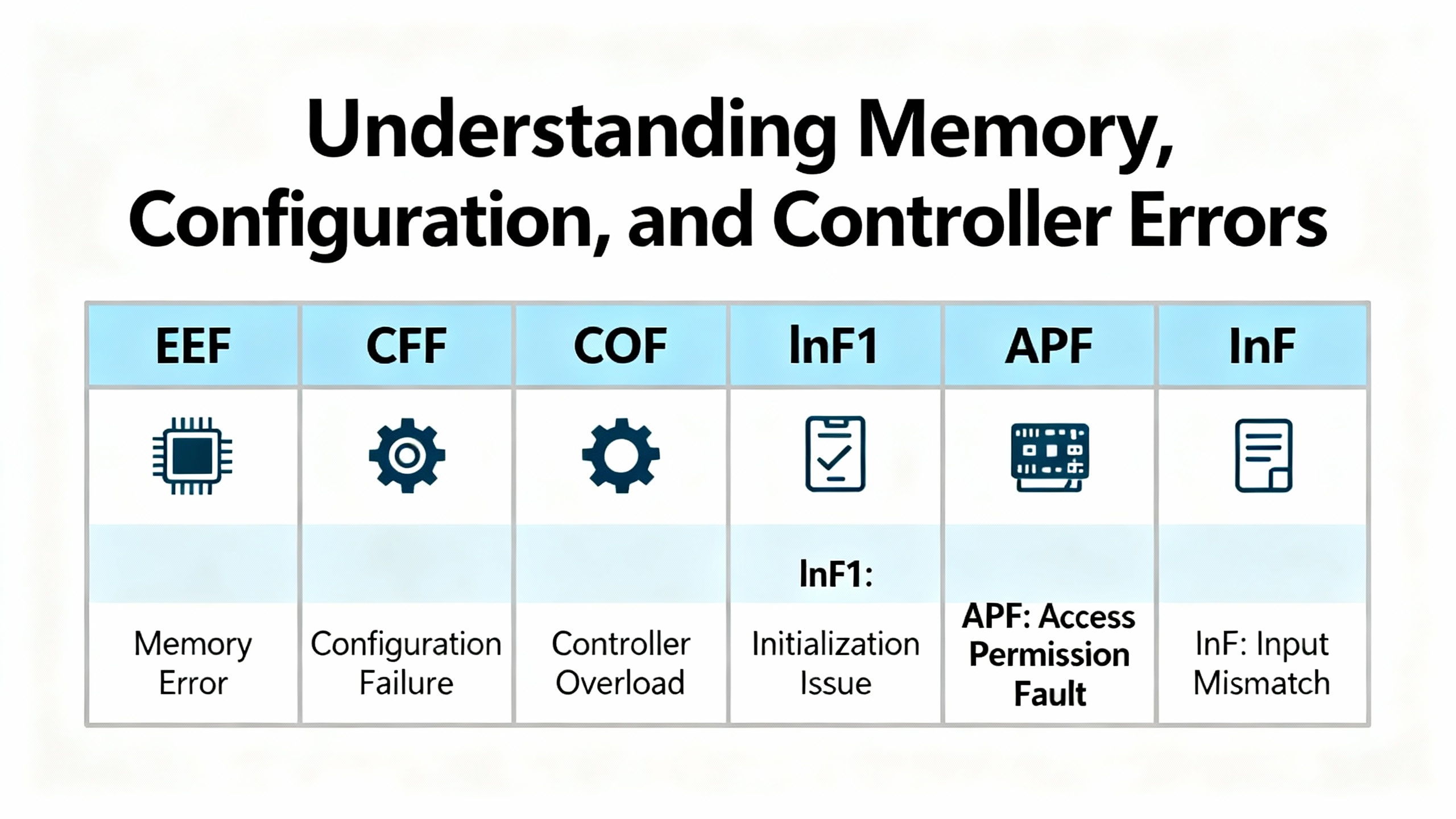
| EEF1, EEF2, CFF, COF, lnF1 | EEPROM, configuration, or power board mismatch | Corrupted parameter store, incompatible board set, incorrect file load | Restore factory defaults and reapply parameters, check hardware compatibility, replace hardware if persistent |
| CrF1, CrF2 | Charge/inrush circuit fault | Precharge components or contactor issue | Inspect the charge circuit and upstream breaker, evaluate inrush components |
| FCF1, LCF | Output switching or input power circuit fault | Internal power circuit problem or upstream feed | Check input contactors and drive power stage health |
| APF, InF | Application or internal device error | Firmware or environment-related faults | Verify installation environment, wiring, grounding, and consider firmware updates or device evaluation |
Model naming matters because the label can shift by family. For example, several Altivar sources summarize that OPF appears as base ŌĆ£OPFŌĆØ in earlier compact lines and as OPF1 or OPF2 in newer process models, while the HVAC-centric ATV212 flags a related output issue as EPHO. Overcurrent appears broadly as OCF across many Schneider series. These correspondences are well documented by Tommy Car Wash Systems, Eltra Trade, and Click2Electro summaries, and they match what I routinely see on plant floors.
Safety Stops and STO: What They Do and How to Prove They Are Healthy
Safe Torque Off (STO) removes the driveŌĆÖs ability to generate torque while the mains and DC bus remain energized. On an Altivar 320, loss of the required 24 VDC at the STO input forces the drive to post STO on the HMI and decouple torque. New drives often ship with a factory jumper from the internal P24 source to the STO input. In real projects, integrators remove that jumper and route a supervised 24 V loop through estops, pull cords, and safety relays so the machine can drop torque safely. When multiple VFDs share a daisy-chained STO circuit, a single broken connection can disable all of them at once. The diagnostic is straightforward: measure at the drive between STO and common and expect approximately 24 VDC when the safety chain is healthy, then tighten terminals, trace upstream through safety devices, and verify the 120 VAC feed to the 24 V supply if that rail is sagging. Schneider ElectricŌĆÖs own guidance matches this proven field workflow, and my experience echoes it: nine times out of ten, it is a loose ferrule or a tired relay contact, not a bad drive.
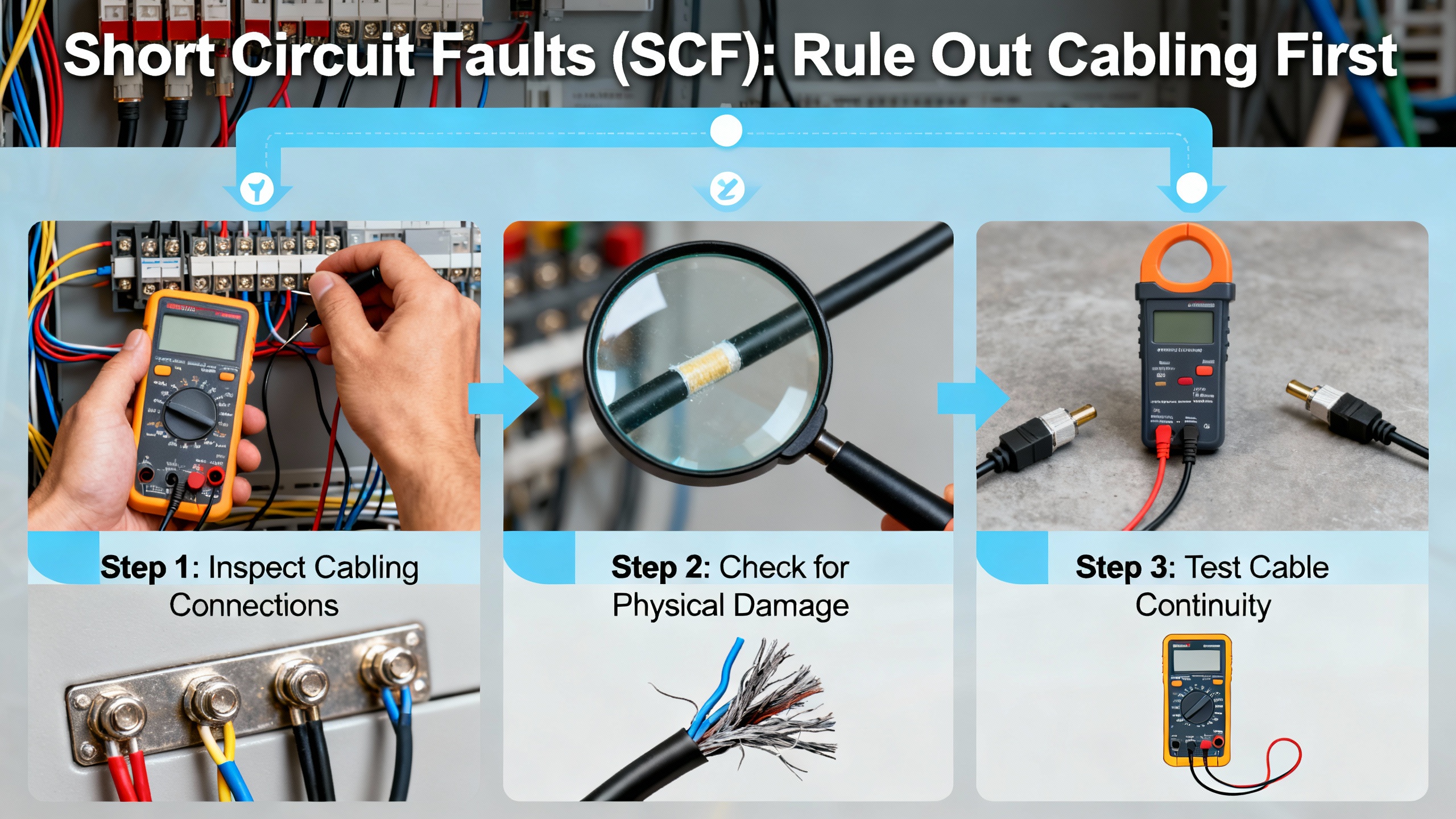
Short Circuit Faults (SCF): Rule Out Cabling First
SCF trips protect the power stage and motor from high fault currents. The most common root causes are cable damage, a pinched motor lead, a mis-terminated shield whisker touching a phase stud, or insulation breakdown in the motor. Click2ElectroŌĆÖs service notes align with best practice: de-energize and inspect the motor power cable for rubs and burns; use a megger to verify phase-to-ground insulation; confirm with a multimeter that no continuity exists between any pair of U, V, and W phases, and none exists from any phase to ground; double-check that the driveŌĆÖs motor parameters match the nameplate; inspect the drive output terminals; and, when in doubt, test the drive on a known-good motor. I have rarely had to swap a drive in the first hour of an SCF call; most failures trace to wiring or the motor.
Overcurrent and Overload (OCF, OLF): Mechanics, Parameters, and Ramps
Overcurrent can be a symptom of mechanical stress as much as electrical. Jams, seized bearings, conveyor snags, or a pump suddenly pushing ice-cold fluid can all spike torque. A too-aggressive acceleration ramp provokes the same outcome, and incorrectly entered nameplate data can make the thermal model and current limit misjudge what is normal. A smart sequence is to decouple or unload the drive, start with a slow acceleration, and observe the current. If no-load current is still high, suspect wiring or the motor windings. If no-load current is normal and load current soars, the problem is likely mechanical. Drive Outlet MegastoreŌĆÖs guidance tracks these steps and adds that extending ramp times and confirming motor data are high-yield fixes. That mirrors my field notes: do not chase parameters until you spin the shaft by hand and feel what the gearbox and bearings are doing.
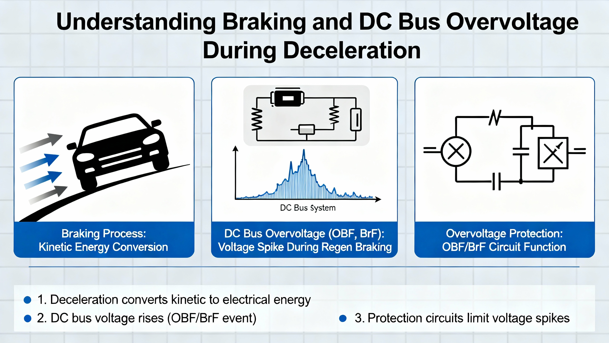
Braking and DC Bus Overvoltage (OBF, BrF) During Deceleration
During a stop, overhauling loads push energy back into the DC bus. Without a place to dump that energy, the bus rises and the drive trips on braking or DC bus overvoltage faults. If your decel time is very short or the loadŌĆÖs inertia is high, use a properly sized braking resistor and confirm the wiring into the braking terminals. When processes can tolerate it, lengthen the decel time to spread out the energy. If trips persist in spite of a correct resistor, look for incoming line surges and add upstream surge protection. This advice is consistent across Tommy Car Wash SystemsŌĆÖ quick references and the troubleshooting flow patterns summarized by Drive Outlet Megastore, and it lines up with process tuning IŌĆÖve done on high-inertia fans and flywheel-fed machines.
Supply Problems (OSF, USF, PHF): Verify What the Drive Sees Under Load
Overvoltage, undervoltage, and phase imbalance are often intermittent, which is why they linger in plants. Loose lugs get warm, then cool, and slowly loosen more. Blown fuses on only one leg leave odd symptoms. Long cable runs drop voltage more than you expect, especially through older disconnects. The right move is to measure line-to-line at the driveŌĆÖs input while the process attempts to run. If the voltage sags, address the upstream cause. PleserviceŌĆÖs overview of Altivar fault families pins the same suspects and calls out phase loss explicitly, and it aligns with general electrical maintenance practice: fix the power path first.

Thermal Trips (OHF, tJF, OtF): Airflow, Ambient, and Workload
Thermal trips speak to heat that cannot escape. Dirty heatsinks and clogged filters, cabinets with poor airflow, a fan that is near the end of its life, or a duty cycle that pushes a drive beyond its intended rating will all present as overtemperature faults. The most reliable cure is not a parameter change; it is cleaning the heat path, strengthening cabinet cooling, and, if necessary, selecting a drive with a thermal design appropriate to the workload. Do SupplyŌĆÖs flowchart reminds teams to treat contamination, humidity, and enclosure temperature as first-class fault causes, and that advice is spot on. Keeping a drive cool extends the life of its electrolytic capacitors and prevents nuisance thermal trips.

Output Phase and Wiring Faults (OPF1, OPF2, EPHO)
When the drive detects a missing output phase, donŌĆÖt overlook the obvious. If a downstream motor disconnect is off, the drive will not see a phase. If a lug was not torqued properly during a motor swap, heat and vibration will expose it. Tommy Car Wash SystemsŌĆÖ Altivar cheat sheet pairs this family of faults with simple corrections: close the disconnect, re-terminate and torque, and inspect for heat damage. In my logs, OPF investigations end happily within a single maintenance window when a technician starts with these basics.
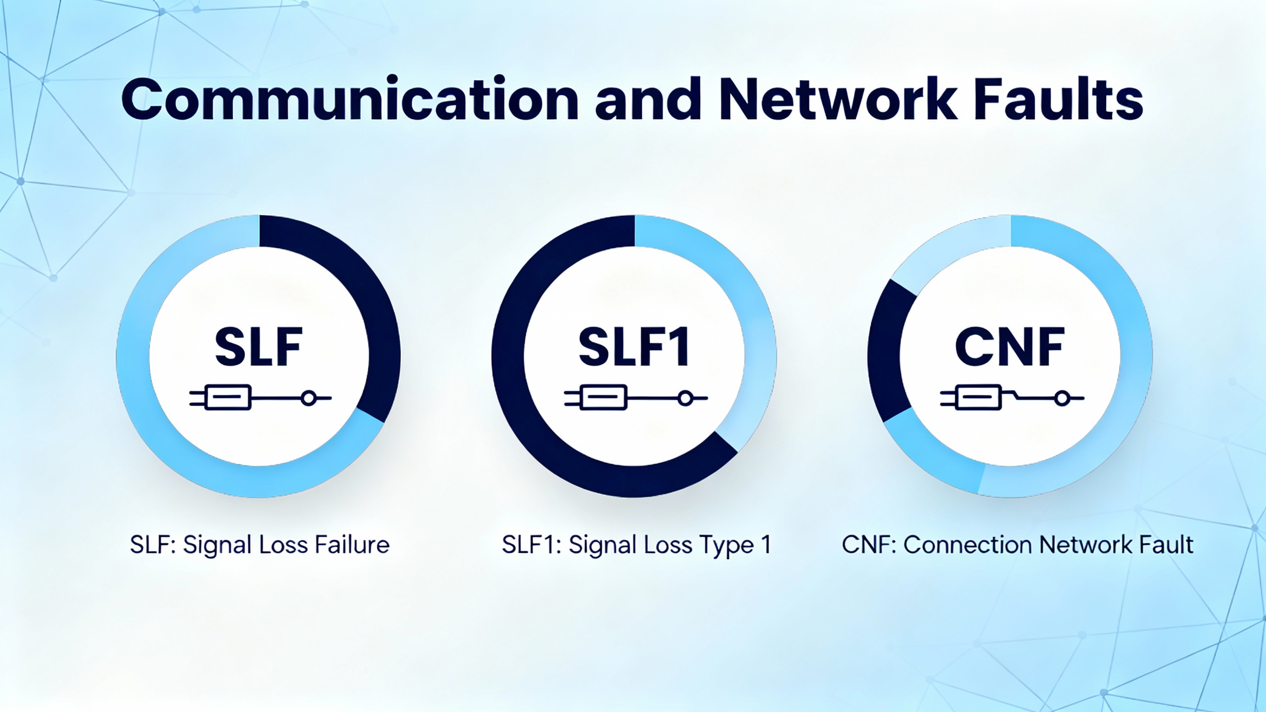
Communication and Network Faults (SLF, SLF1, CNF)
Communication faults have clear patterns and fixes that Schneider Electric documents repeatedly. If a drive cannot be seen on the network, confirm the protocol is the one you selected in the controller, verify the cable and pinout, check addressing and baud or data rate, and remember a drive must be power-cycled for an address change to take effect. For Ethernet, the controller and drive must share the same IP network and subnet mask. If the drive intermittently trips on a communication fault, add or verify end-of-line termination where the standard requires it, ground the communication cable at the controller side to avoid ground loops, increase the network timeout, and route the comms run away from high-voltage conductors. If plugging in a drive crashes the network, check for duplicate addresses and reversed terminal polarity on serial runs. Schneider ElectricŌĆÖs support notes detail exactly these points, and they are the checklist I use on every RSŌĆæ485, CANopen, and Ethernet integration. Tommy Car Wash SystemsŌĆÖ service sheet highlights a common field fix for SLF alarms on compact series too: power cycle first to clear a transient loss of communication, then swap the RJ45 or check the Modbus router if errors persist.
| Symptom | Likely cause | Verification | Correction |
| Drive not visible on network | Wrong protocol, bad cable, wrong address or baud, address changed without power cycle | Confirm protocol in controller and drive, inspect cable, read drive address, verify baud settings | Select the correct protocol, fix cabling, set address and baud correctly, power cycle the drive |
| Intermittent communication fault | Missing termination, noise pickup, timeouts too short, excessive device count | Check termination resistors, inspect cable routing, review timeout settings, count nodes | Install termination, reroute or shield, ground comm cable at controller side, increase timeout |
| Network crash when drive plugs in | Duplicate address, reversed terminals | Scan addresses, verify A/B polarity | Assign unique addresses, correct polarity |
| Fault at run command tied to network | Ground path or switching frequency coupling, supply topology | Verify motor ground to the drive, review switching frequency, identify corner-grounded or high-leg systems | Bond motor ground to drive, reduce switching frequency, isolate or adapt the input filter, test run with motor disconnected |
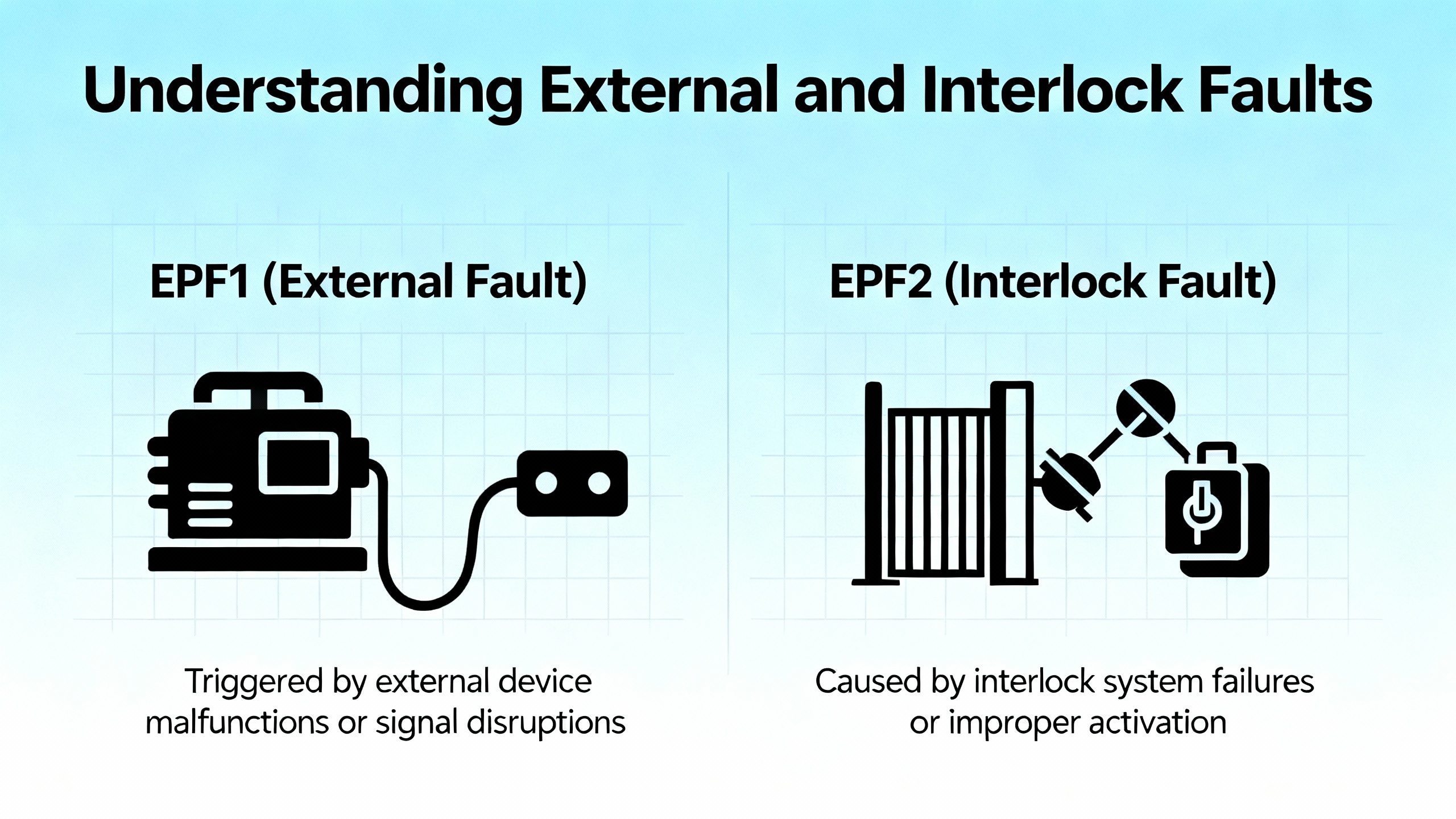
External and Interlock Faults (EPF1, EPF2)
An EPF code reports that an external device has requested a trip, either as a simple dry contact wired into the drive or through the network. These are not cleared at the drive until the external source returns to normal. The right approach is to find the external fault, solve that root cause, and then reset. Attempting to override or bypass these is poor practice and undermines the systemŌĆÖs safety posture.
Analog Input Loss (AI2F, LFF2ŌĆōLFF4)
When an Altivar relies on a 4ŌĆō20 mA reference for speed or torque and the loop opens, the drive flags a missing signal. Across Altivar documentation and service briefs, the same checks apply: verify loop power, confirm continuity end to end, check the transmitter or process sensor, and validate scaling or loss-of-signal fallback parameters. A missing loop is not a drive problem until you prove the loop is healthy.
Memory, Configuration, and Controller Errors (EEF, CFF, COF, lnF1, APF, InF)
These codes point to data integrity or incompatible combinations of hardware and configuration. Eltra TradeŌĆÖs overview outlines power cycling, restoring factory defaults, reloading correct parameters, and in the case of persistent EEPROM faults, replacing the device. Always confirm the power board and control board match the drive model and that configuration files correspond to the exact version. If you capture these events in your maintenance log along with the corrective actions, repeat episodes are far faster to resolve.
A Focus Case: ATV340 ŌĆ£Load Movement ErrorŌĆØ (nLdCF or MDCF)
One Altivar 340 pattern that merits special attention is the load movement trip. The drive detects motion when none is commanded and posts a load movement fault, often labeled nLdCF or as hexadecimal 0050 on some screen variants. In hoisting and vertical axis applications, this is a serious condition because unintended drift risks injured people and dropped loads. Analysis guidance compiled by Longi highlights five causes and the associated corrections.
Brake systems come first. If the brake command circuit has loose wiring or a failing relay, the brake will not hold; if the brake is worn or misadjusted, holding torque is insufficient. Parameters also matter. The driveŌĆÖs load movement detection must be enabled, the torque threshold reference must be set to match the load and mechanics, the motor control type must match the motor (field-oriented settings differ for synchronous and asynchronous machines), and the load holding time after power restoration must be long enough for the application. Loose couplings, gears, or belts can allow drift even with a stopped motor, as can an unstable center of gravity or inadequate fixtures. Electrical and external influences such as voltage fluctuations and strong electromagnetic interference can perturb control. External forces such as wind on a hoist load produce the same symptoms in the field.
| ATV340 item | What to verify | Practical note |
| Brake command circuit and brake health | Test continuity through the brake relay path; manually check the brakeŌĆÖs hold and release | Replace or re-adjust worn brakes; many drift calls end here |
| Load movement detection | Ensure the detection feature is enabled | This function is disabled by default on some configurations |
| Torque threshold reference | Set to a value appropriate for your loadŌĆÖs behavior | Too low triggers nuisance trips, too high misses real drift |
| Motor control type | Select settings that match the motor type | Field-oriented control modes differ for synchronous vs. asynchronous |
| Load holding time after power restore | Lengthen within the supported range to match your application | The default is short; extending helps prevent false trips |
| Mechanical fixity | Tighten or replace couplings, belts, and gears | Look for witness marks and slippage |
| Electrical environment | Maintain stable supply and reduce interference | Add shielding or rearrange cabling where needed |
Once you remove the root cause, clear the code by issuing a reset command or by cycling power if your operating practice requires a cold start. Automatic restart can be enabled to help a system recover, but use it thoughtfully on vertical axes. If your process involves cranes, lifts, or elevators, build a structured acceptance test that proves the brake, the parameterization, and the detection work together before releasing the system back to production.
Model Variations: Same Ideas, Different Labels
SchneiderŌĆÖs Altivar families have evolved through the 11/12/21/31/32/58/61/66/71/212/312/320/630/640/340 series and more. Fault labels vary slightly by series, but the underlying categories are consistent. Tommy Car Wash Systems catalogs patterns like SLF or SLF1 for communication errors in compact lines, OBF for braking faults in compact and process lines, OPF1 and OPF2 for output phase issues in process variants, and EPHO for the HVAC-focused Altivar 212. Click2ElectroŌĆÖs Altivar 71 references group encoder errors, braking issues, charge circuit faults, power circuit faults, ground faults, overheating, overloads, analog input losses, memory and controller errors, and external interlocks in a way that aligns with later series as well. Eltra TradeŌĆÖs aggregation for the Altivar 71 also describes practical reset tools such as a device reset parameter and auto-restart sequences, which echo the same operational philosophy in newer hardware. The point is not to memorize each label but to recognize the family and then consult the specific series manual for code matching and detailed corrective steps.

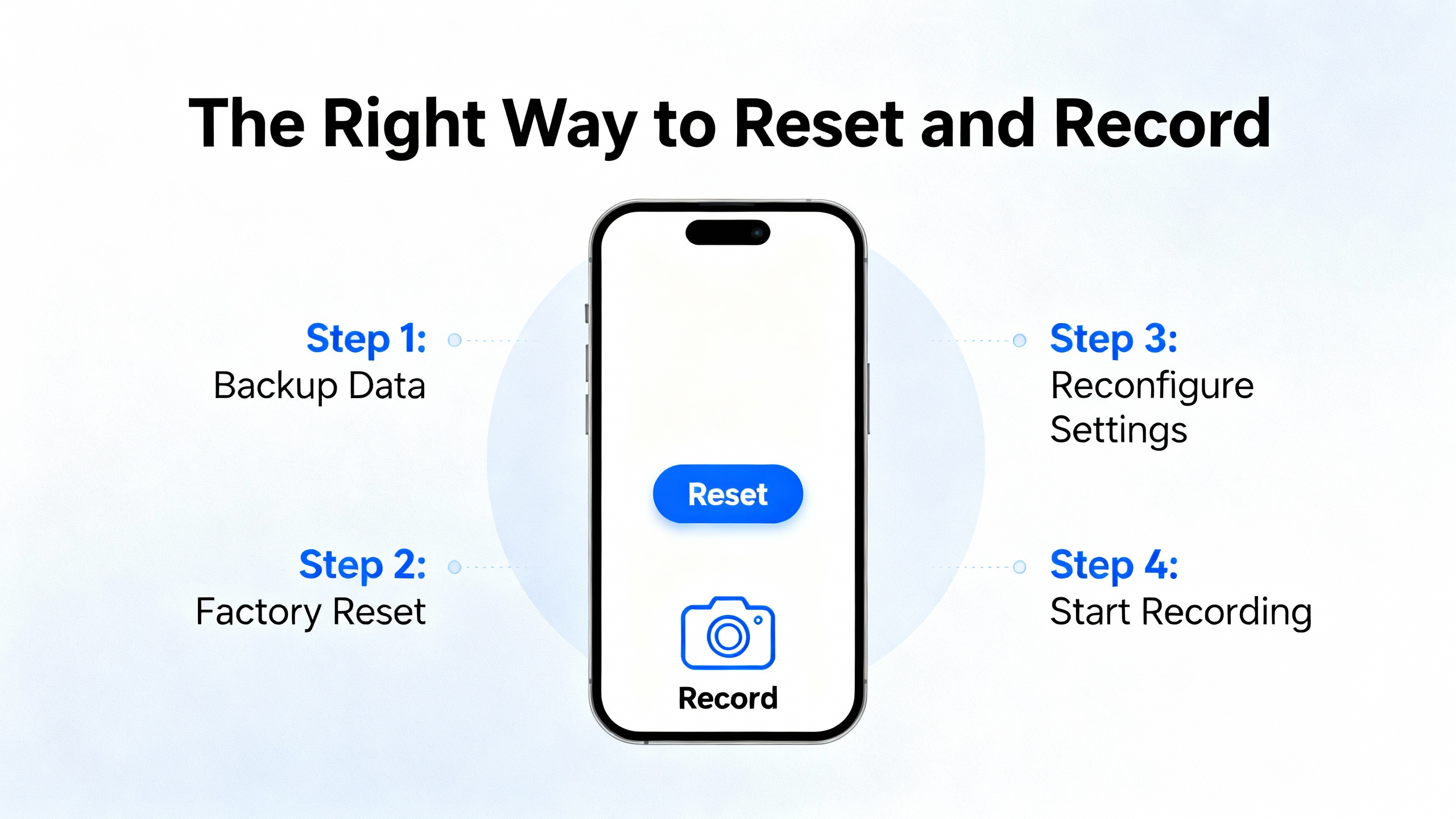
The Right Way to Reset and Record
After a corrective action, reset the trip through the keypad, a mapped digital input, or the control word. Power cycling is useful when you need to be certain everything reinitializes cleanly. Auto-restart can reduce manual intervention, yet it must be restricted to applications where it is safe to resume automatically. Most importantly, keep a short fault log with the code, timestamp, root cause, and fix. Click2Electro and Eltra Trade both recommend this habit, and it pays off. If a nuisance code becomes a trend, you will see it in the logs before it becomes a true failure.
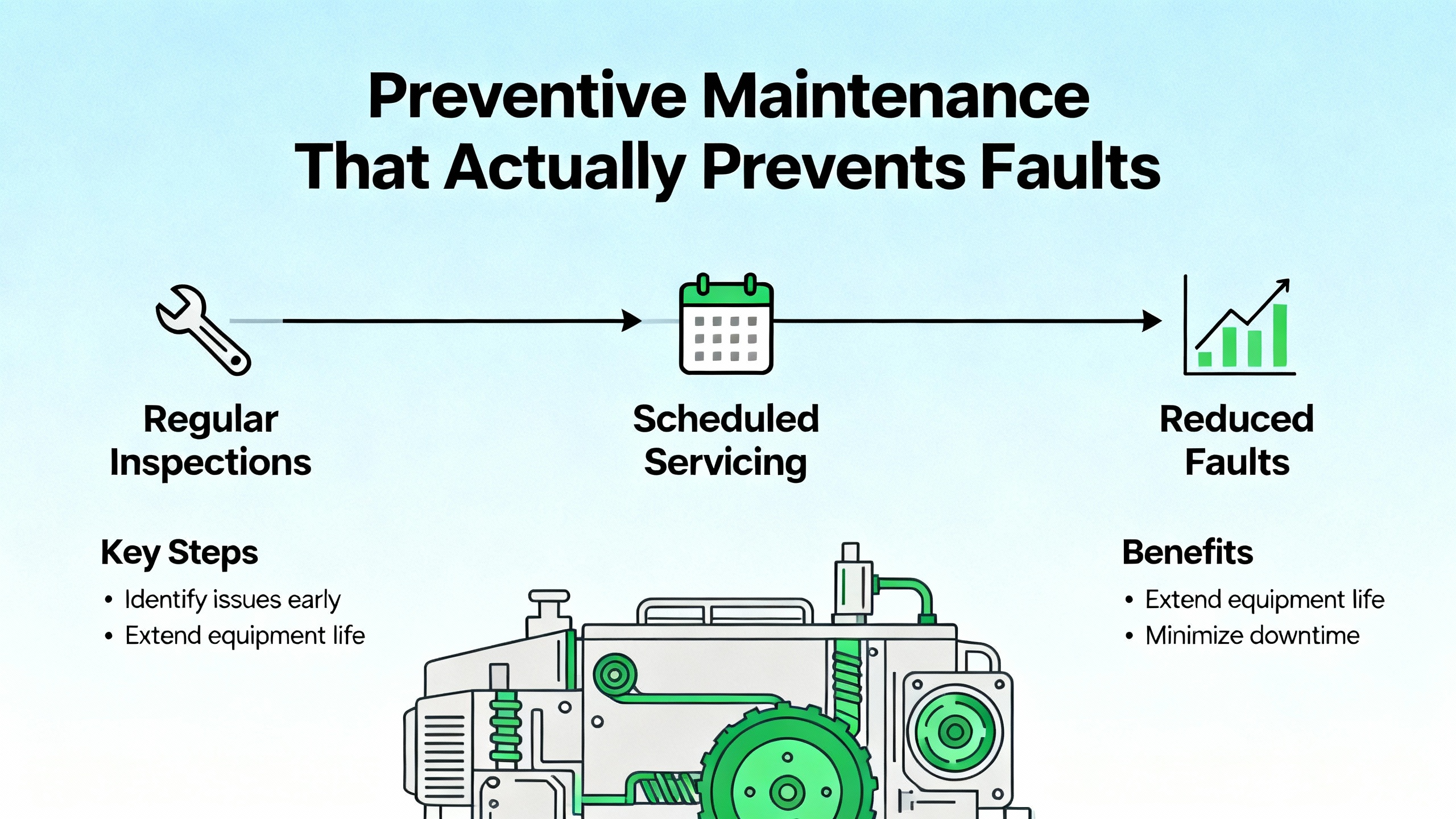
Preventive Maintenance That Actually Prevents Faults
Clean the driveŌĆÖs intake and heatsink surfaces to maintain cooling. Keep humidity in check to avoid condensation and PCB corrosion. Verify tightness and condition of power lugs as part of a seasonal or semiannual PM round. Use a pyrometer or temperature probe to spot hot connections that indicate loosening. Treat DC bus health as a consumable; electrolytic capacitors age faster at higher temperatures, so keeping the enclosure cool extends life and reliability. These habits reflect Do SupplyŌĆÖs troubleshooting guidance and mirror the simplest wins I see across facilities: cleanliness, airflow, tight terminations, and documented observations.
Pros and Cons of Common Settings and Strategies
Auto-restart improves uptime in lightly loaded, nonhazardous applications and cuts nuisance human intervention, but on hoists or where unexpected motion is unsafe, it should remain off. Higher PWM switching frequency can help with audible noise and smooth torque in some applications, yet it increases IGBT and drive thermal stress; use it only when needed and when enclosure cooling is robust. Ground fault sensitivity set very tight catches more issues early, yet on long motor leads or with high EMI, it can produce nuisance trips; use proper VFD-rated cable, terminate shields thoughtfully, and consider output filters for long runs rather than desensitizing protection. Daisy-chained STO circuits simplify safety wiring across multiple drives, yet a single bad device can disable all; segment where appropriate and provide clear diagnostics at each drive to localize a safety chain break fast. These are tradeoffs I advise on frequently; the smart choice balances uptime and safety within the process hazard analysis.
Short FAQ
Does a power cycle clear every Altivar fault?
Power cycling resets most conditions, but it does not fix the underlying cause. Some configuration and memory errors persist until you restore defaults and reload parameters. External faults and STO remain until the external chain is healthy. Use a fault reset or device reset where supported if a cold start is not desirable, but pair resets with a measured fix.
When should I suspect a bad drive rather than the motor or wiring?
Short circuit faults that persist with a known-good motor and verified cables, or internal power circuit faults reported as switching or input power circuit failures, are candidates for drive evaluation or replacement. Before condemning a drive, rerun the motor uncoupled, megger the cable and motor, confirm nameplate parameters, and check supply quality under load. My field failure rate for power stages is far lower than the rate for cable and motor insulation problems.
Do I need a braking resistor for every deceleration fault?
Not always. Many decel trips resolve by lengthening the ramp to spread the energy in time. A braking resistor becomes necessary when the loadŌĆÖs inertia and required stop time combine to produce more regenerative energy than the DC bus can tolerate. When you install one, size it using the driveŌĆÖs data and the loadŌĆÖs kinetic energy, and confirm wiring and resistor placement for heat dissipation.
Closing
Altivar fault codes are a precise diagnostic language. Learn the families, follow a disciplined workflow, and you will turn trips into quick, safe recoveries. Start with power, wiring, and mechanics; confirm parameters; prove safety loops; and record what you did. When you treat the driveŌĆÖs messages as actionable data, you trade guesswork for reliability. That is how I keep plants running, and it is how you can make your next Altivar fault a short chapter rather than a long story.
References
- https://epubl.ktu.edu/object/elaba:124681442/124681442.pdf
- https://www.energy.wsu.edu/Portals/0/Documents/PNNL_WSU_RCM_Webinar%202017-05-31_Final.pdf
- http://docs.eao.hawaii.edu/UKIRT/mech/workstation/02_altivar_28/altivar28_rs485.pdf
- https://www.longi.net/schneider-atv340-load-movement-error-analysis-and-solutions/?srsltid=AfmBOooPUl47d2qC852LTMJraFAco9fWNYGpqRMJ0BwSC3rSmnIJJXXr
- https://anadiautomation.com/blog-details/vfd-fault-codes
- https://driveoutletmegastore.com/understanding-vfd-fault-codes/?srsltid=AfmBOooI7l0rcVZ3IX-REnJ1RHK9tvWQ_zLzRfCPmuMRe8XKQuG_V78D
- https://eltra-trade.com/blog/schneider-electric-altivar-71-fault-codes
- https://dashboard.intelligrated.com/knowledgebase/PrintArticle.aspx?article=c6e12058-f510-45fd-9d09-6ae9576adb08
- https://forums.mikeholt.com/threads/altivar-630-ground-motor-short-circuit-faults-motor-trouble-too.2575587/
- https://www.scribd.com/document/412765060/MMC-Card


 Videos
 News
News Applications


Leave Your Comment