Invensys Triconex safety systems sit in the same category as your UPS-backed switchgear and inverter-fed control power: they exist so that when everything else goes wrong, people and equipment stay safe. In many plants, Triconex racks protect highŌĆæhazard processes while UPS systems and rectifier banks keep those racks energized through grid disturbances. When any of the safety system components age out, go obsolete, or suffer degraded performance, your overall risk profile changes immediately.
This guide walks through how to think about Triconex replacement parts from a safety, power, and reliability perspective. It pulls together guidance from Triconex safety documentation, fieldŌĆæproven rectifier and maintenance practices, and reliability research from organizations such as the University of TennesseeŌĆÖs Reliability and Maintainability Center. The goal is practical: help you choose, qualify, and maintain replacement parts so that your safety system continues to perform as designed, even as hardware generations change around it.
Why Triconex Replacement Parts Matter in PowerŌĆæCritical Facilities
Triconex is a safety instrumented system (SIS) platform widely deployed in oil and gas, petrochemicals, and other highŌĆæhazard industries. As summarized by Moore Process Controls, it uses triple modular redundancy (TMR) and is certified to high Safety Integrity Levels (SIL 3 and SIL 4) for emergency shutdowns, burner management systems, fire and gas protection, and highŌĆæintegrity pressure protection. That means every module in the rack participates in risk reduction that regulators and insurers assume will be there when demanded.
The reliability and maintainability literature makes the stakes very clear. The University of TennesseeŌĆÖs Reliability and Maintainability Center cites Aberdeen Research data putting the average cost of unplanned downtime at about $260,000 per hour. The same article notes that improving equipment reliability can increase production output by up to 20 percent and that strong maintainability can cut equipment replacement costs by as much as 25 percent according to McKinsey & Company. For safety systems, those economics sit on top of an even more basic obligation: preventing accidents that could injure people or damage the environment.
In practice, safety systems are tightly coupled to your power infrastructure. Rectifier modules and UPS systems feed the DC buses that keep Triconex racks and field I/O alive. Modern rectifier modules, as described in rectifierŌĆæmaintenance guidance for telecom and data environments, can reach around 97.1 percent efficiency initially and about 98.5 percent with upgrades, reducing conversion losses and cooling energy by roughly 22 percent versus older designs. When you replace power or logic modules in a Triconex architecture without the same rigor you apply to your main power train, you risk creating weak links that may only show up during a trip demand or power disturbance.
That is why replacement parts for Triconex systems cannot be treated as commodity spares. They are safetyŌĆæcritical components in a certified architecture, and each decision about sourcing and installation has implications for power reliability, safety integrity, and longŌĆæterm maintainability.
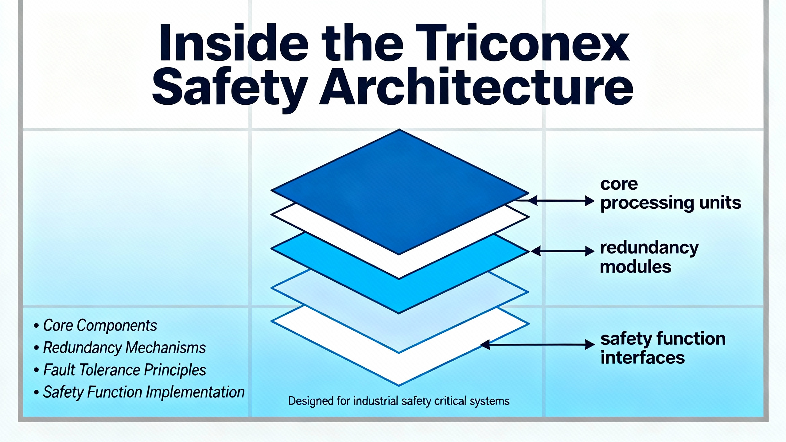
Inside the Triconex Safety Architecture
Triconex platforms are built around a TMR architecture. Three parallel processors execute the same safety logic, and a voting mechanism selects the majority result. If one channel deviates because of a hardware or logic fault, the other two can outŌĆævote it so the system continues running safely. This is what Moore Process Controls describes as fault tolerance and ŌĆ£safe failureŌĆØ behavior, and it is a major reason Triconex is used for SIL 3 and SIL 4 safety instrumented functions.
These systems are separate from the basic process control system. Burner management guidance from industry safety sources emphasizes that safetyŌĆæcritical burner logic should be implemented on an independent, certified safety controller rather than embedded in the DCS. Triconex systems embody that philosophy by providing a dedicated SIS layer that integrates with DCS, HMIs, and historians but maintains its own certified logic, communication, and diagnostics.
Triconex architectures typically include:
Controllers and processors that execute safety logic and manage diagnostics.
Input and output modules that interface to field devices such as pressure switches, transmitters, valves, and burner igniters.
Communication and expansion modules that connect multiple racks, remote I/O drops, or other systems.
Power, control integration, and maintenance modules that manage energy distribution, module health, and diagnostics.
EcoStruxure Triconex product information from Schneider Electric highlights how newer Tricon CX generations blend features from previous Tricon, Trident, and earlier Tricon CX systems into a unified, modern platform for safety and critical control. That evolution matters when you plan replacements: many facilities run mixed fleets of legacy and newer modules, and replacement strategies must respect the certified combinations and firmware baselines across generations.
Triconex Component Families and Replacement Roles
Triconex replacement parts span several functional families. A recent component guide from NewGen Automation describes a range of module types used across Triconex installations, from controllers to I/O, communications, and maintenance modules. While specific part numbers vary, the replacement logic tends to follow the functional category.
A simplified way to view the component families and their replacement implications is summarized below.
| Component family | Example modules mentioned in literature | Primary role in the system | Replacement focus |
| Master controllers and CPUs | 4409, 3805H, 3007, 3381 | RealŌĆætime execution of safety logic, diagnostics, and sequencing | Ensure firmware compatibility, maintain TMR integrity, and follow OEM migration paths when upgrading generations. |
| I/O and feedback modules | 4354, 3603T, AO3481 S2, 3481 S2, 3806E, 2211, 4200, 4353 | Interfacing with field sensors and final elements, providing accurate measurement and actuation | Match signal type and range exactly, validate channel diagnostics, and reŌĆæperform proof tests after replacement. |
| Communication and expansion modules | 3603B, 3625A, 3706, 4352B | Linking racks, remote I/O, and other control systems | Preserve network topology and protocol settings; reŌĆæverify peerŌĆætoŌĆæpeer links and diagnostics. |
| Power and control integration modules | 4329G, 3505E, 3664, 8111 | DC power distribution, redundancy, and logic interfacing | Coordinate with rectifiers and UPS systems, verify load sharing and redundancy, and monitor temperatures. |
| Specialized and highŌĆædemand modules | 8112, 4201, 8110, 3721 | HighŌĆæprecision or highŌĆæload duties in demanding applications | Confirm operating limits and thermal margins, especially when ambient or loading has increased. |
| Maintenance and diagnostics modules | 3511, 8311, 4329, 3009 | Diagnostics, maintenance support, and serviceability features | Keep versions aligned with monitoring tools and predictive maintenance platforms. |
This classification reinforces an important point: not all replacement decisions carry the same type of risk. Replacing a diagnostics support module incorrectly may degrade visibility or maintenance efficiency, while replacing a controller or output module incorrectly can change how a safety loop behaves under fault conditions. Your replacement strategy should reflect that difference in criticality.
EndŌĆæofŌĆæLife, Obsolescence, and When to Replace
In the real world, many Triconex replacement decisions are triggered by symptoms rather than a clean, timeŌĆæbased plan. A forum discussion on an Automation & Control Engineering platform offers a good illustration. An engineer shared operational data from a Triconex TCM communication module and asked peers whether it was approaching end of life. A responding engineer concluded that, in his opinion, the TCM module was in an endŌĆæofŌĆælife condition and recommended planning a replacement. He also noted an important missing diagnostic input: rackŌĆælevel temperature measurements, which would have helped explain the degradation and make the case with the original manufacturer.
That case highlights three practical lessons for replacement decisions.
First, endŌĆæofŌĆælife is often detectable in the data before hard failure. Subtle communication errors, increased diagnostic events, or intermittent behavior on a TCM or I/O module are flashing indicators that it is time to plan a replacement, not just reset alarms.
Second, environmental data matters. Without inŌĆærack temperature and environmental history, it is much harder to assess whether a module has been overstressed or whether a systemic cooling problem will also kill its replacement. Rectifier maintenance guidance underscores this point: dust and poor airflow drive overheating and premature failures. Cleaning rectifiers and enclosures every three to six months, using dry methods such as compressed air, is recommended precisely to avoid heatŌĆærelated issues.
Third, obsolescence and vendor support must be considered explicitly. As EcoStruxure Triconex evolves, older modules and firmware generations reach formal end of support. University of Tennessee RMC case studies show that structured, reliabilityŌĆæcentered maintenance programs at companies like General Electric and Boeing deliver doubleŌĆædigit reductions in maintenance cost and significant reliability gains. Similar lifecycle thinking applied to Triconex modules means proactively planning obsolescence upgrades rather than waiting for hard failures in unsupported hardware.
In practice, that means maintaining an explicit bill of materials for each rack, mapping modules to lifecycle status, and scheduling replacements for atŌĆærisk parts before they surprise you during a shutdown or power event.
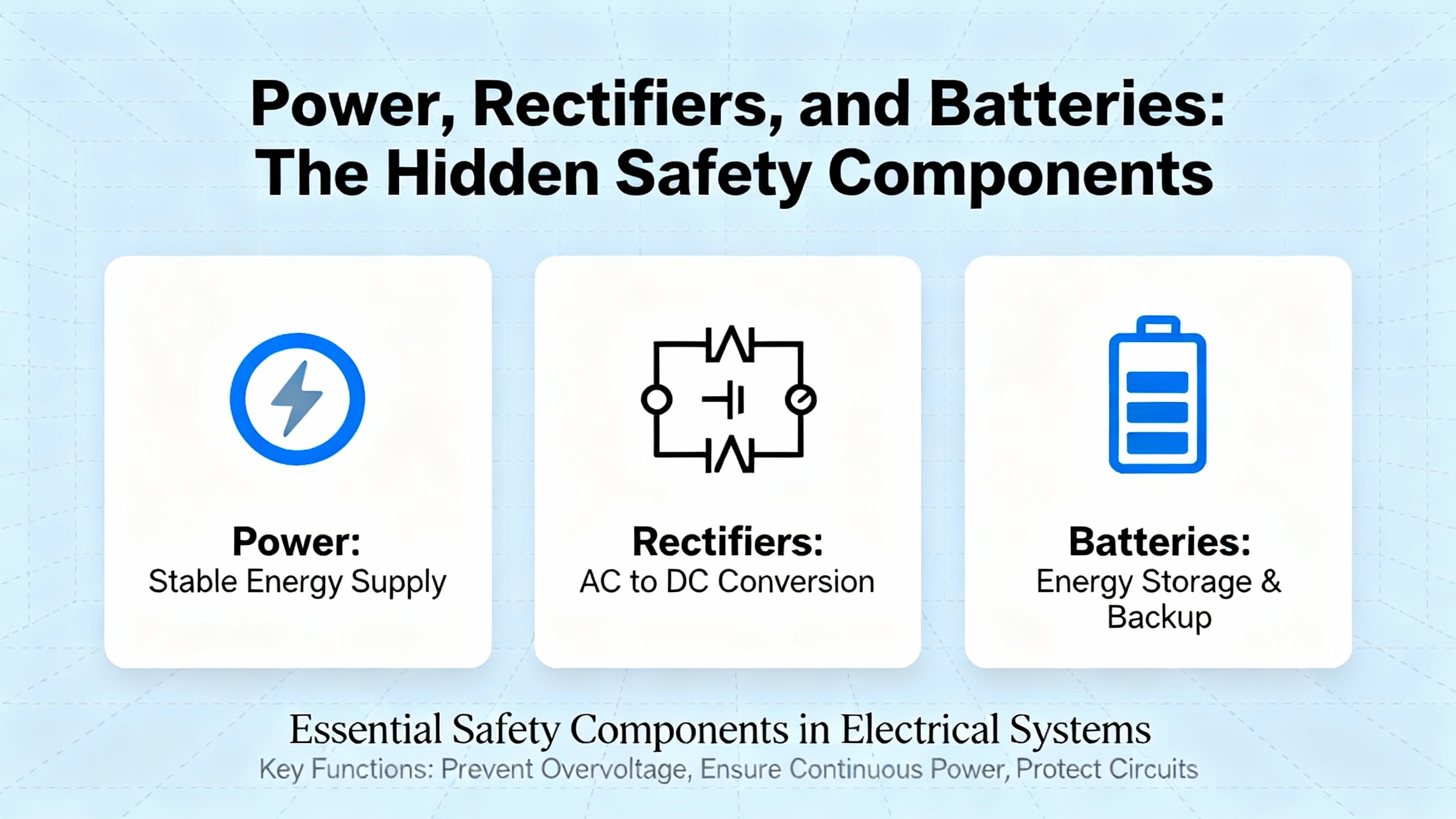
Power, Rectifiers, and Batteries: The Hidden Safety Components
For a Triconex system, ŌĆ£replacement partsŌĆØ include not only logic and I/O modules but also every device that feeds them reliable power. The rectifiers and UPS systems in your DC room are the primary safety net for the SIS, and they deserve the same attention.
Rectifier modules used in telecom and data center power systems, as described in rectifierŌĆæmaintenance sources, frequently supply up to about 2,900 watts of DC output, with rackŌĆæmounted configurations around 900 watts per module. Modern highŌĆæefficiency rectifiers reaching approximately 97 to 98.5 percent efficiency reduce conversion losses and can cut cooling energy requirements by around 22 percent relative to older designs. Given that the global rectifier market is forecast to grow from roughly $7.24 billion in 2024 to about $10.5 billion by 2035, with telecom rectifiers alone rising from about $0.95 billion to around $1.5 billion, it is clear that rectifiers are no longer commodity items but strategic assets.
The same logic applies in safety system applications. If a Triconex rack relies on aging rectifiers or poorly maintained DC distribution, replacing logic modules without addressing the power chain is a halfŌĆæmeasure. Core preventive actions drawn from rectifier maintenance practices that translate directly into Triconex environments include:
Routine cleaning of modules and surrounding spaces every few months, more often in dusty areas, using dry cleaning methods to keep heatsinks and airflow paths clear.
Continuous monitoring of voltage, current, and temperature, feeding anomalies into predictive maintenance analytics.
Regular inspection of connections and components for looseness, corrosion, or discoloration that might indicate overheating or impending failure.
Firmware updates and log reviews on smart rectifiers and power controllers at least quarterly, to correct bugs and improve efficiency and reliability.
For Triconex specifically, battery replacement is another often overlooked replacement activity that directly affects safety performance. A Triconex planning and installation guide excerpt discusses the procedure for battery replacement in Tricon v9ŌĆōv10 systems: removing the access cover, noting the original battery orientation, inserting the replacement batteries with the positive terminal facing the correct direction, and carefully reinstalling the cover so both locking tabs engage. These details may seem purely mechanical, but incorrect orientation or poor contact can compromise the retention of critical configuration or timekeeping data, or reduce the confidence that the system will behave as expected on restart.
The practical implication is simple. When you plan a Triconex module upgrade or replacement, treat the rectifiers, DC distribution, and batteries as part of the same work package. Verify that power modules are from highŌĆæquality sources, that efficiency is adequate, that thermal margins are respected, and that batteries are within their recommended replacement window and correctly installed. This integrated view aligns with Schneider ElectricŌĆÖs positioning of EcoStruxure Triconex as a safety and critical control platform that protects production, people, and profits, rather than just a set of logic modules on a rack.
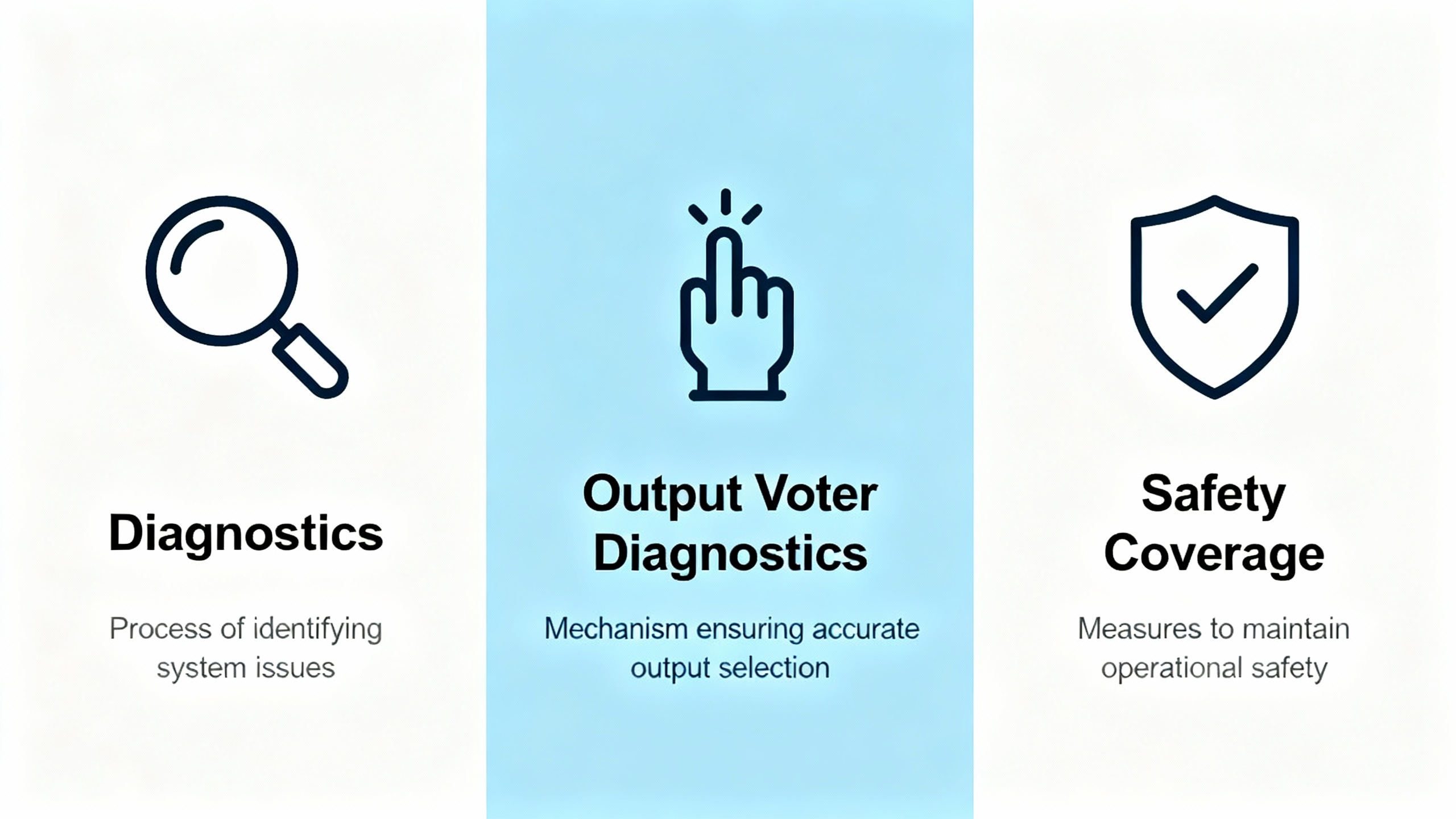
Diagnostics, Output Voter Diagnostics, and Safety Coverage
Some replacement decisions are less about hardware and more about how diagnostics are used. A Triconex planning and installation guide section on Output Voter Diagnostics (OVD) for digital output modules illustrates this tension clearly.
OVD provides failure detection of output components. When enabled, it can achieve essentially 100 percent failure detection for output components, which is particularly important for outputs that spend long periods in a single state, such as drives or valves that are almost always energized. The problem is that in some systems, OVD can cause glitches that interfere with the controlled process. As a result, some operators disable OVD to avoid nuisance behavior.
The recommended compromise is to periodically enable OVD even if it cannot be left on continuously. The guidance describes an approach where the process is safely shut down, the TriStation controller panel is used to enable OVD on previously disabled modules, and diagnostics are allowed to run for several minutes to verify module stability and exercise the outputs. After the verification period, OVD can be disabled again if required.
For safetyŌĆærelated programs, however, the guidance is explicit that disabling OVD is not recommended and should only be done when absolutely necessary. If OVD must be disabled in a safety application, digital outputs must be proofŌĆætested every three to six months to compensate for the reduced continuous diagnostic coverage.
When you replace digital output modules, this guidance should be treated as part of the replacement plan. Questions to resolve include whether the new module family has the same OVD behavior, whether OVD is enabled by default, how proofŌĆætest intervals are set in your maintenance program, and how you will demonstrate 100 percent diagnostic coverage or equivalent through testing. A module swap that downgrades diagnostics without updating proofŌĆætesting practice undermines the safety case, even if the hardware itself is newer.
Selecting and Qualifying Replacement Parts
Choosing a replacement Triconex component is not a simple ŌĆ£likeŌĆæforŌĆælikeŌĆØ exercise, especially as platforms evolve from earlier Tricon and Trident to Tricon CX generations. The NewGen overview of Triconex components stresses the importance of compatibility, operating requirements, safety needs, and scalability when selecting modules such as 4211, 3624, 3720, or 3008. It also highlights that futureŌĆæproofing is best achieved through modular, componentŌĆæbased upgrades, such as adopting updated modules like 4351B V11.5, 3625, 3674, or 3708E, rather than ripping and replacing whole systems.
Several practical principles emerge.
Compatibility with existing racks and firmware comes first. Master controllers like 4409 or 3805H, and communication modules such as 3603B or 3625A, must fit within certified combinations. Introducing a newer controller into a legacy rack without aligning firmware and configuration can create subtle incompatibilities, especially in safety logic execution and diagnostics.
Safety integrity and application requirements must be rechecked. Safety considerations guides for Triconex General Purpose v2 systems describe how features such as TMR, diagnostics, and application guidelines support SIL 2 and higher applications. When you change modules in a safety instrumented function, you need to verify that the replacement maintains or improves the safety integrity level, rather than assuming it does so automatically.
Maintainability and diagnostic features should influence selection. NewGen points to modules such as 3511, 8311, 4329, and 3009 as maintenanceŌĆæfocused, supporting diagnosticŌĆæfriendly designs. Combined with predictive maintenance strategies that rely on sensors and controlŌĆæstage data, these modules help detect deviations in temperature or voltage early and shorten recovery times. Given that predictive maintenance has already become standard in many rectifier productsŌĆöwith more than oneŌĆæthird of new rectifiers including smart controls and nearly half shipping with predictiveŌĆæmaintenance software by 2024ŌĆöchoosing Triconex modules that integrate well with such analytics is a strategic advantage.
LongŌĆæterm scalability and obsolescence planning close the loop. New modules such as 3607E, 4119A, 4351A, 3636T, 4351B, 3504E, and 3805E are designed to enable incremental upgrades and extended life. A carefully planned roadmap that phases in these components as older hardware reaches the end of its supported life can defer major capital expenditures, echoing McKinseyŌĆÖs observation that strong maintainability practices can reduce equipment replacement costs by up to 25 percent.
In short, treat Triconex replacement parts as elements in a lifecycle strategy: validate compatibility, confirm safety integrity, maximize diagnostic value, and map each decision into a longerŌĆæterm architecture plan.
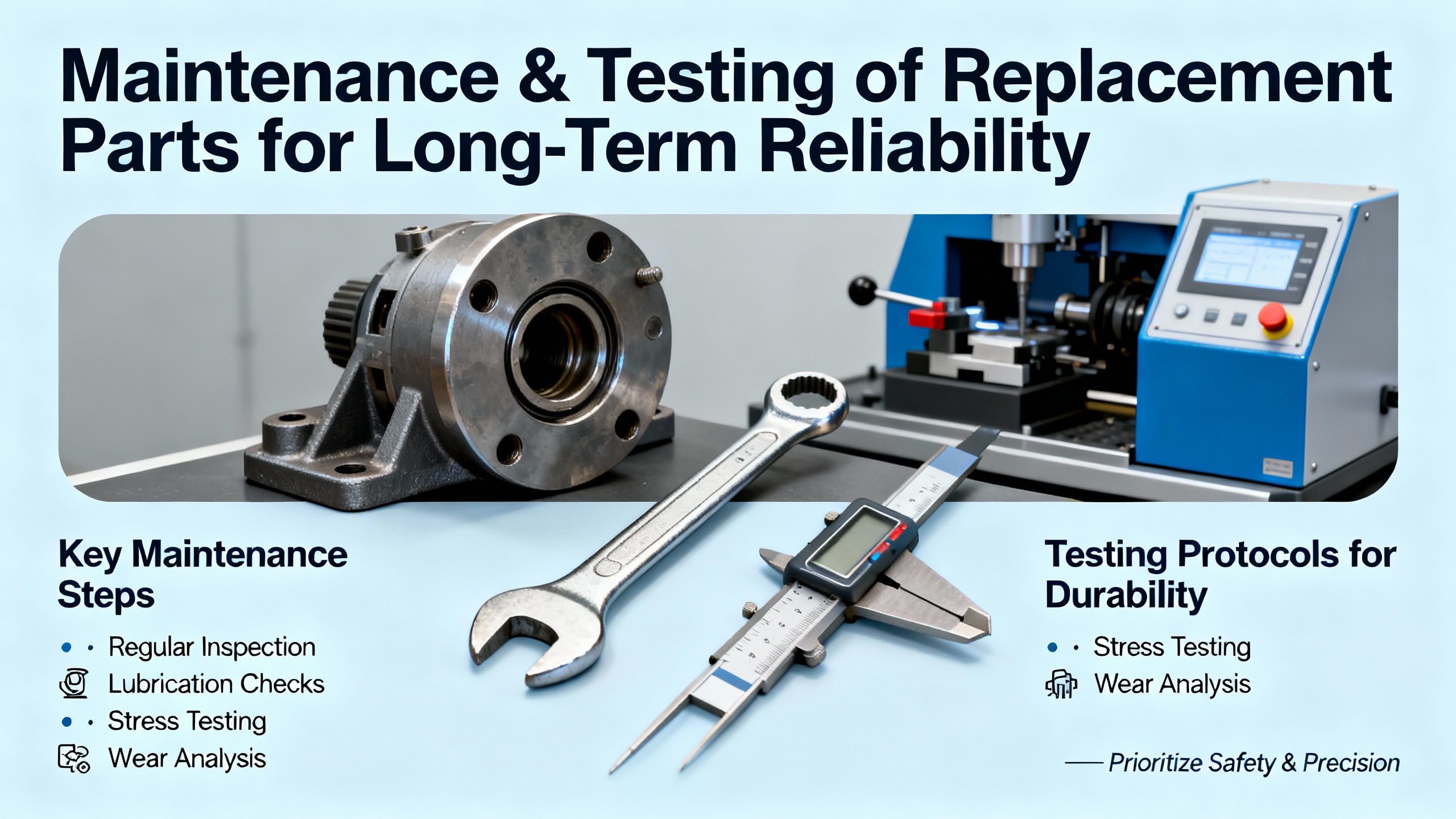
Maintenance and Testing of Replacement Parts for LongŌĆæTerm Reliability
Installing a replacement part is only the first half of the reliability story. The way you maintain that part determines whether you actually capture the risk reduction and economic benefits you expect.
Rectifier maintenance guidelines provide a useful pattern that can be adapted to Triconex modules. A structured schedule recommended for rectifier systems includes monthly connection checks, basic cleaning, and voltage monitoring; quarterly firmware updates and deeper internal cleaning; and annual part replacement, calibration, and conditionŌĆæbased failure prediction. Applying similar structure to Triconex racks will dramatically improve reliability and maintainability.
A practical way to think about maintenance cadence for Triconex and its supporting power infrastructure is summarized below.
| Interval | Focus for Triconex and supporting power | Typical actions derived from industry guidance |
| Monthly | Basic health and cleanliness | Visually inspect module status LEDs and diagnostics, check rack and panel cleanliness, verify rectifier and UPS status, and review basic voltage and temperature readings for anomalies. |
| Quarterly | Firmware, software, and deeper inspection | Apply tested firmware and software updates to rectifiers and maintenance modules, review system logs for recurring diagnostics, perform deeper cleaning of racks and power equipment, and verify that network and communication modules (such as 3603B or 3625A) show stable operation. |
| Every 3ŌĆō6 months | Safety diagnostics and proof testing | If Output Voter Diagnostics are disabled on any digital output modules, perform proof tests at least every three to six months; schedule periodic OVD enablement windows during safe process shutdowns to exercise diagnostics and confirm 100 percent failure detection where possible. |
| Annually | Condition assessment and replacement planning | Perform thorough inspections of all safety and power modules, including thermal imaging where available; evaluate environmental history (temperatures, dust, load factors); identify TCM or other modules that show endŌĆæofŌĆælife symptoms; and update the obsolescence and replacement roadmap. |
Reliability research summarized by the University of TennesseeŌĆÖs Reliability and Maintainability Center shows that companies like General Electric, after adopting reliabilityŌĆæcentered maintenance, achieved around a 30 percent reduction in maintenance costs and a 20 percent increase in equipment reliability. Boeing observed a 15 percent reduction in maintenance costs and a 25 percent increase in aircraft availability with predictive maintenance and data analytics. Safety systems benefit similarly when treated with structured reliability programs: fewer unexpected module failures, better uptime, and a stronger safety case.
For Triconex systems, this means embedding maintenance of replacement parts in your formal reliability and safety lifecycle, rather than handling them as ad hoc repairs. It also means training maintenance personnel in the specifics of safety diagnostics, proof testing, and configuration management so that each replacement and maintenance action preserves the integrity of the safety instrumented functions.
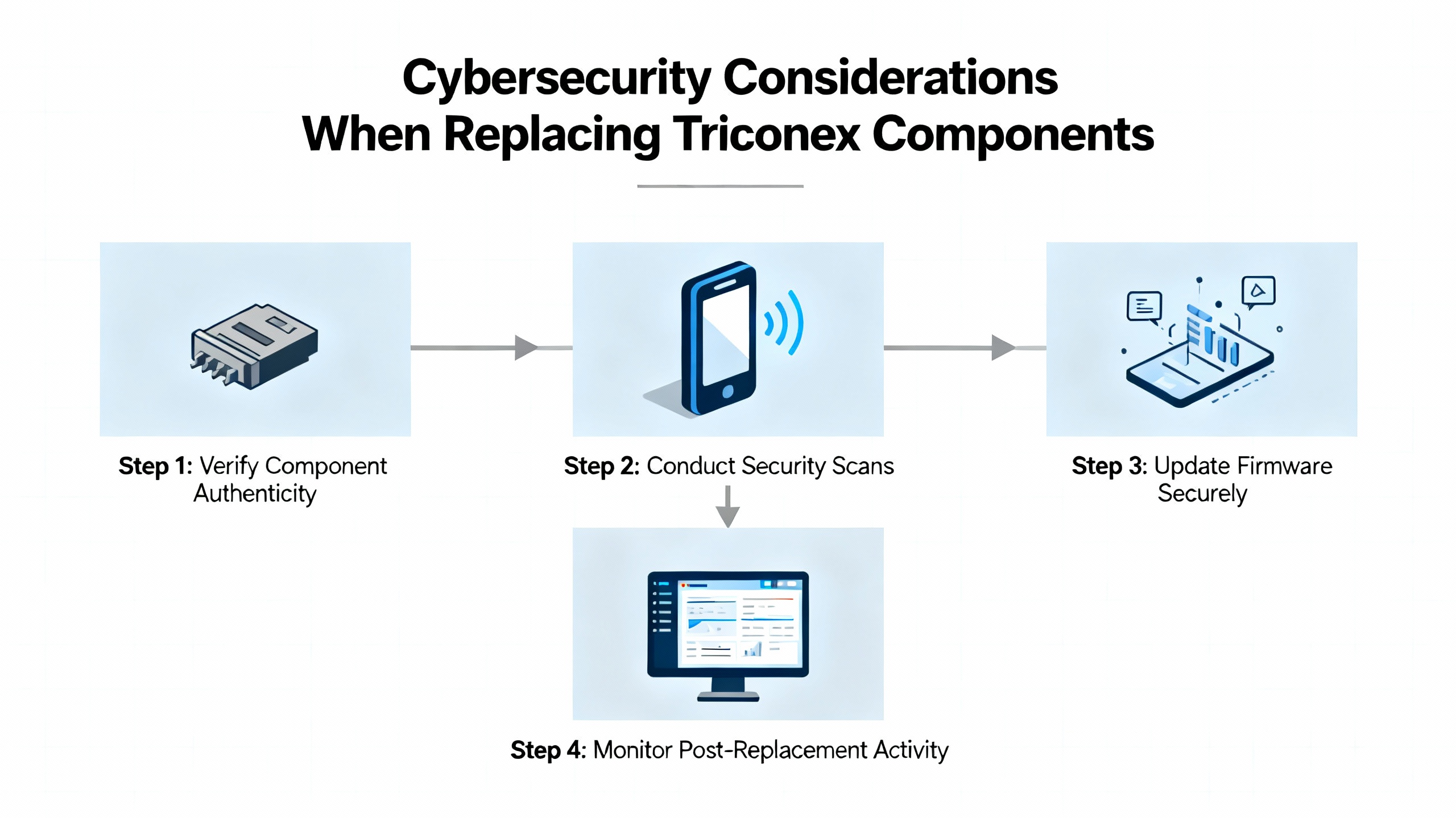
Cybersecurity Considerations When Replacing Triconex Components
Modern Triconex systems such as EcoStruxure Triconex combine functional safety with embedded cybersecurity features. Schneider ElectricŌĆÖs cybersecurity guidance for these systems emphasizes that cyber threats to safety instrumented systems are not theoretical. Attacks on SIS controllers, ransomware on engineering workstations, and unauthorized access to safety networks are all realistic risks.
When you replace controllers, communication modules, or engineering workstations associated with Triconex, cybersecurity must be part of the acceptance criteria. Recommended practices for EcoStruxure Triconex environments include:
Maintaining defenseŌĆæinŌĆædepth network architecture with strong segmentation between corporate IT, basic process control networks, and the safety network, with carefully configured firewalls and demilitarized zones.
Hardening systems by disabling unused services and ports, enforcing roleŌĆæbased authentication, and enabling detailed logging on engineering and operator stations.
Managing patches and vulnerabilities in a riskŌĆæbased manner: testing patches in a staging environment, scheduling updates around plant operations, and following vendor security advisories.
Tightly controlling remote access, using secure jump hosts, virtual private networks, multiŌĆæfactor authentication, timeŌĆælimited sessions, and avoiding direct remote access to safety controllers wherever possible.
Integrating cybersecurity into the functional safety lifecycle, aligning with standards such as IEC 61511 and IEC 62443, so that risk assessments, design, implementation, operation, and decommissioning all consider cyber as well as process risk.
In practical terms, replacing a Triconex controller or communication module today often means enabling or changing cybersecurity features compared with the hardware it replaces. Those changes can affect everything from how firmware is loaded to who can modify safety logic. Treating cybersecurity as a formal acceptance test criterion for replacement parts is essential to maintaining both safety and security objectives.
FAQ: Practical Questions About Triconex Replacement Parts
How do I know when a Triconex module is truly at end of life rather than just experiencing a transient fault?
Look beyond a single diagnostic event. Persistent or increasing communication errors, recurring diagnostic alarms on the same module, unexplained resets, or thermal abnormalities are indicators that a module such as a TCM or I/O card is nearing end of life. The forum discussion where an engineer classified a TCM module as end of life based on operational evidence illustrates that trendŌĆæbased analysis is more valuable than isolated faults. Including rackŌĆælevel temperature and environmental data strengthens your case and helps distinguish between a weak module and a systemic cooling or loading issue.
What is the safest way to handle Output Voter Diagnostics when replacing digital output modules?
If your process can tolerate it, the safest approach is to keep Output Voter Diagnostics enabled continuously after replacing digital output modules. OVD provides essentially full failure detection for output components, which is especially important for outputs that remain in one state for long periods. If OVD causes unacceptable process glitches and must be disabled, follow the Triconex guidance to perform proof testing of those digital outputs every three to six months and plan periodic windows where OVD is reŌĆæenabled during a safe process shutdown to exercise diagnostics.
Where do rectifiers and UPS systems fit into my Triconex replacement strategy?
Rectifiers and UPS systems are part of the safety systemŌĆÖs lifeline. RectifierŌĆæmaintenance guidance shows that modern, efficient rectifiers with smart monitoring reduce energy waste, improve thermal margins, and support predictive maintenance. When you plan Triconex replacements, include rectifier modules, DC distribution hardware, and UPS systems in the scope. Verify that power modules have adequate capacity, that cooling and airflow are maintained, that firmware and monitoring are up to date, and that batteries are replaced and installed correctly. A new Triconex controller sitting on top of a weak DC power train undermines both safety and reliability.
Closing
Treating Invensys Triconex replacement parts as a structured reliability and safety engineering problemŌĆörather than as a spareŌĆæparts exerciseŌĆöpays off in protected people, stable production, and fewer unpleasant surprises during power events or trip demands. By combining certified Triconex hardware, disciplined power and rectifier maintenance, rigorous diagnostics and proof testing, and modern cybersecurity practices, you build a safety system that continues to earn its place as the last line of defense in your plant.
References
- https://scholarspace.library.gwu.edu/downloads/qb98mf88c?locale=en
- https://rmc.utk.edu/the-importance-of-reliability-and-maintainability-in-manufacturing/
- https://www.nrc.gov/docs/ml0932/ml093290420.pdf
- https://iceweb.eit.edu.au/BurnerManagement/SafetyConsiderationsGuide.pdf
- https://www.mooreplc.com/blog/the-impact-of-triconex-in-automation-in-the-oil-and-gas-industry_b152
- https://blog.outdoortelecomcabinet.com/maintaining-rectifier-modules-tips/
- https://www.rms-dcs.com/uploads/3625.pdf
- https://www.newgenplc.com/blogs/news/triconex-comprehensive-guide-to-industrial-automation-components-and-optimization?srsltid=AfmBOopDf_xop7WaWp43rHeH0hdmXPXs3INAHYrCtW8cbSQUNhmoX6eg
- https://www.scribd.com/document/387086132/Reemplazo-bateria-Triconex
- https://control.com/forums/threads/triconex-tcm-module-life-time.52954/


 Videos
 News
News Applications


Leave Your Comment