Industrial power systems are increasingly dynamic. UPS installations, inverter-fed drives, high-efficiency pumps, and automated materials handling all rely on electric motors that must start, stop, and synchronize with precision. The common thread behind those motions is not just the drive or the PLC, but the encoder that closes the feedback loop. When the encoder is wrong, the entire systemŌĆÖs reliability suffers, no matter how robust the UPS or power protection may be.
Drawing on encoder guides from Anaheim Automation, Dynapar, HEIDENHAIN, Encoder Products Company, Timken, US Digital, and others, this article walks through how encoders work, how to choose among technologies, and what to look for in an industrial encoder supplier when motion feedback is mission-critical.
Why Motion Feedback Matters in Power-Critical Facilities
In any closed-loop control system, the controller compares a command with measured feedback and adjusts the output to minimize error. In motion control, the dominant feedback device is the encoder, which measures displacement or velocity and sends signals back to the drive or PLC. Anaheim Automation describes encoders as sensors of mechanical motion that generate digital signals representing position, velocity, and direction.
In power-critical facilities, the stability and availability of motion control is often just as important as the stability of the voltage bus. If a conveyor driven by an inverter loses position feedback, a UPS can keep the drive powered, but it cannot prevent misaligned product or mechanical damage. If a gantry in a battery plant or semiconductor fab loses reference after a brief outage, the restart time is driven by how quickly position can be re-established, not by how fast the UPS transfers.
Reliable encoders therefore become part of the overall power and protection strategy. They make sure that when power is present, motion is under control, and when power is lost, the system can resume safely without guesswork.
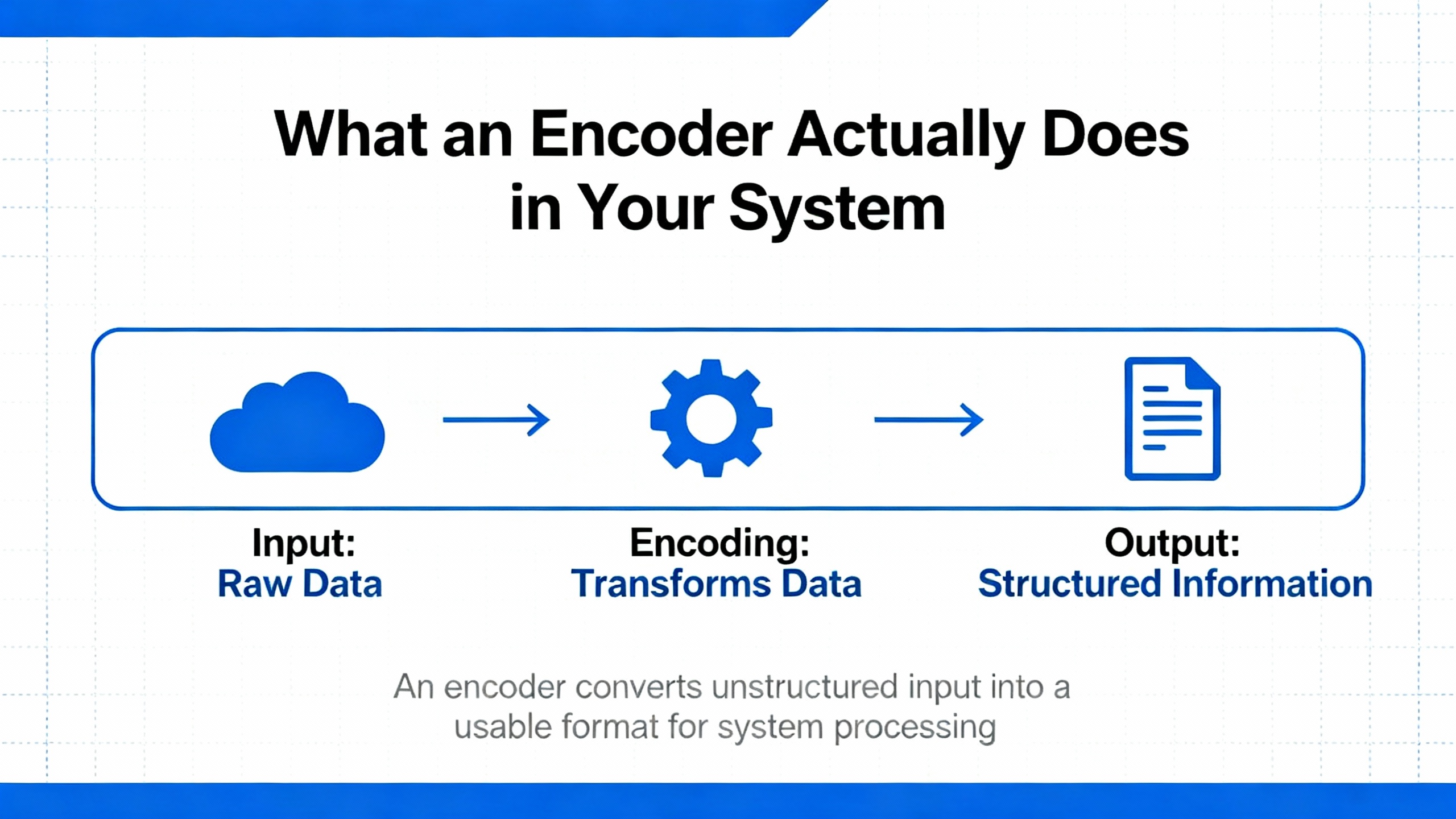
What an Encoder Actually Does in Your System
A motor encoder converts mechanical motion into electrical signals that a controller or PLC can understand. Sources such as Control.com and Dynapar characterize encoders as position sensors that report shaft angle, speed, direction, or linear displacement.
In practical terms, the encoder is typically mounted on a motor shaft, a gearbox output, or a linear axis. As the shaft rotates or the carriage moves, the encoder produces either pulses or digital codes. The motion controller counts these pulses or interprets the codes to calculate speed, distance, angle, and direction. In conveyor lines, encoders help maintain constant speed and precise indexing. In CNC machines and 3D printers, linear encoders translate scale markings into extremely fine linear position feedback. In robotics, rotary encoders attached to joints allow coordinated multi-axis motion.
Encoders are equally at home in harsh industrial automation, medical and scientific instruments, transportation, and even office equipment like printers and scanners. Encoder Products Company, for example, notes that encoders are used to monitor speed, rate, direction, distance, and position in nearly every industrial sector.
From a power-systems viewpoint, the encoder is on the ŌĆ£information sideŌĆØ of the drive, but it is exposed to the same electrical disturbances and environmental stress that affect the power equipment. That is why encoder technology and supplier quality matter so much.
Core Encoder Families and Where They Fit
Rotary vs Linear Motion Feedback
Encoder references consistently split devices into rotary and linear families. Rotary encoders mount to a rotating shaft and measure angular position or speed. They are common on motors, spindles, and rotary tables. Linear encoders use a readhead and a scale to convert straight-line motion into signals. Optical linear encoders use a light source, scanning reticle, and glass scale; magnetic linear encoders use a magnetic strip and a sensor that generate TTL or analog signals.
Linear encoders excel in sliding axes on high-speed, high-accuracy machinery such as CNC mills, 3D printers, and precision inspection systems. Rotary encoders dominate in servo motor feedback, conveyors, robotic arms, and applications where the primary quantity of interest is angular position or shaft speed.
In power-critical plants, you will often see both. A crane or elevator application might use rotary encoders on motor shafts for speed control and linear encoders or draw-wire encoders on the load for lift height or travel distance.
Incremental vs Absolute Position Feedback
The second major division is incremental versus absolute encoders. This distinction has direct implications for how a system behaves after power loss, which is central for UPS-backed or generator-backed installations.
Incremental encoders generate evenly spaced pulses as motion occurs. A typical quadrature encoder has two channels, A and B, shifted by 90 electrical degrees so the controller can infer direction as well as speed and position. Many incremental encoders add a Z or index pulse once per revolution for homing. However, incremental encoders only provide relative position. After a power cycle, the controller must re-establish a reference, usually by moving to a home switch or reference mark.
Absolute encoders, by contrast, assign a unique digital pattern to every mechanical position. Anaheim Automation describes absolute optical encoders that use concentric patterns and Gray code to output a distinct bit word for each shaft angle. HEIDENHAIN and others extend the concept with single-turn absolute encoders that track position within one revolution, and multi-turn encoders that also count the number of revolutions. The key advantage is that the system knows where it is immediately after power-up without a homing move.
In simple applications where the system can safely move on startup, incremental encoders are cost-effective and widely used. In systems where motion after an outage is constrained, heavy, or safety-critical, the additional cost and integration effort of absolute encoders are often justified. Vendors such as HEIDENHAIN, Dynapar, and Rockwell Automation emphasize this choice as a foundational selection decision.
Single-Turn, Multi-Turn, and Distance-Coded Designs
Within the absolute category, suppliers like HEIDENHAIN further distinguish single-turn encoders, multi-turn encoders, and distance-coded solutions. Single-turn devices measure angle within 360 degrees and work well for applications like antenna pointing or local pivot positioning. Multi-turn encoders track many revolutions and suit cranes, wind turbine pitch systems, and long-travel axes.
Distance-coded encoders combine incremental lines with specially spaced reference marks so that absolute position can be determined after moving only a short distance, which is valuable when a full homing cycle is not acceptable but some small startup motion is permissible.
For large linear or rotary systems powered through UPSs, distance-coded and multi-turn encoders can reduce restart time after power events because the machine does not need to traverse its entire travel to find a reference.
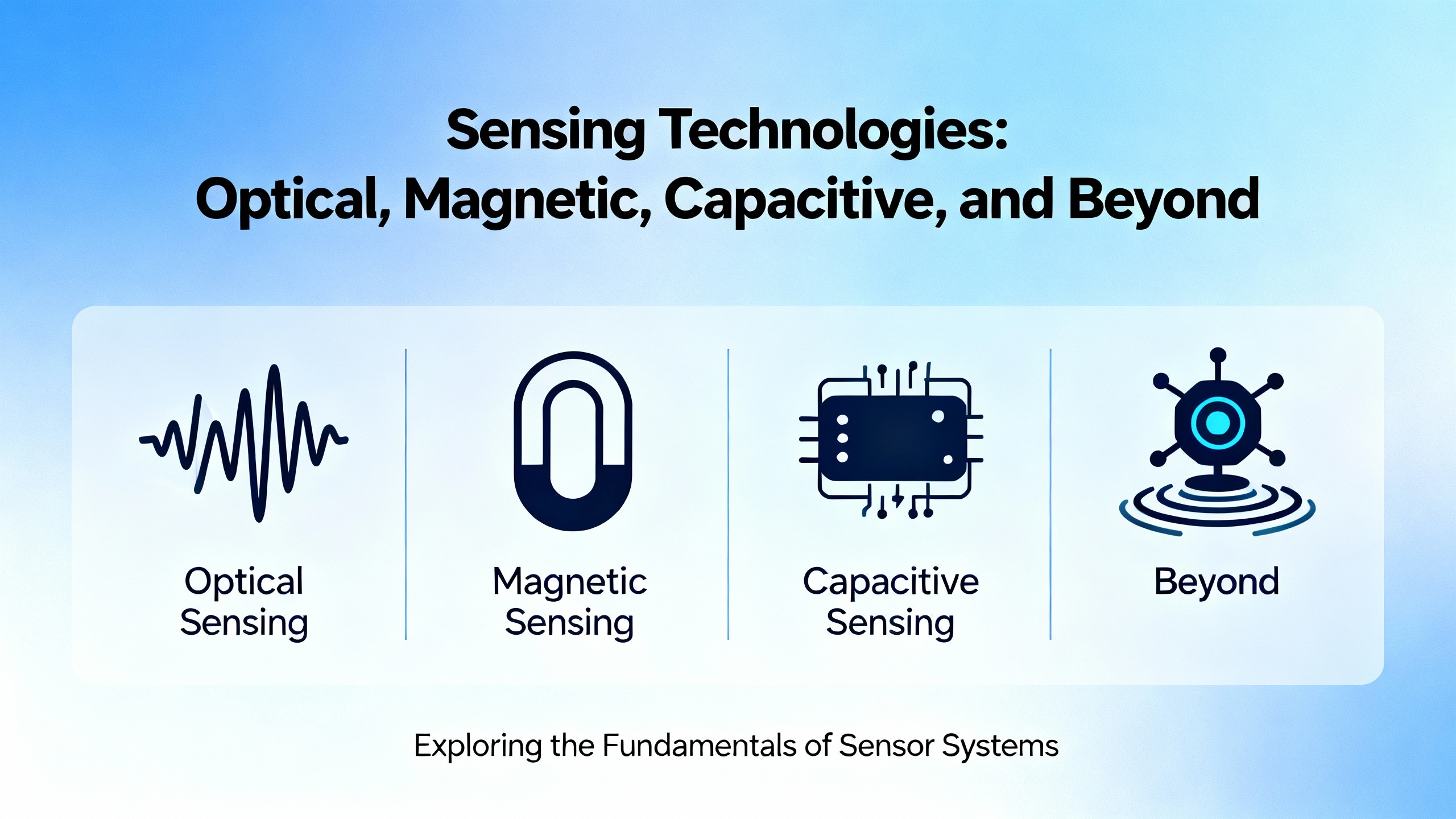
Sensing Technologies: Optical, Magnetic, Capacitive, and Beyond
Optical Encoders: High Precision with Clean Conditions
Optical encoders are the workhorse of high-precision motion control. Anaheim Automation explains that an optical encoder uses a transparent disk with opaque segments. An LED shines through the disk onto a photodetector; as the disk turns, the alternating light and dark regions create electrical signals.
Multiple sources, including Motion Control Tips and US Digital, highlight several consistent advantages. Optical encoders offer high resolution and accuracy, and they are common in manufacturing, robotics, packaging, and machine assembly. They can be manufactured with fine line patterns that yield many thousands of counts per revolution or very high linear density.
The tradeoff is environmental sensitivity. Optical encoders are more vulnerable to heat, mechanical shock, humidity, dust, and oil unless they are sealed and packaged specifically for harsh-duty environments. HEIDENHAIN and others note that exposed optical encoders deliver outstanding accuracy in clean environments such as semiconductor tools, while sealed optical encoders are designed for machine tools and other dirty environments with coolant, chips, and vibration.
From a reliability advisorŌĆÖs perspective, optical encoders are ideal where the environment can be controlled or where sealed housings and appropriate IP ratings are feasible. They should be paired with robust mounting, strain relief, and power conditioning to protect the LED and sensor electronics from surges and temperature extremes.
Magnetic Encoders: Rugged Feedback for Harsh Duty
Magnetic encoders replace the optical disk with a magnetized rotor and sensors that detect changes in the magnetic field. Anaheim Automation describes designs using Hall-effect or magnetoresistive sensors and alternating north-south poles around the rotor. Electromate and TechBriefs note that magnetic encoders can be either incremental or absolute.
These devices trade some resolution and signal purity for mechanical robustness. Anaheim Automation points out that magnetic encoders tolerate oil, dirt, and water and avoid many optical failure modes such as seal leaks and shattered disks. Dynapar and HEIDENHAIN add that magnetic encoders are attractive in mining, steel, pulp and paper, and washdown food and beverage applications where contamination is expected.
However, the notes also call out limitations. Anaheim Automation and Maxon mention that low-cost Hall-effect devices tend to exhibit more signal jitter and lower resolution than comparable optical encoders. Magnetic encoders can also be sensitive to stray magnetic fields, including those from the motor itself or nearby high-current conductors. In some designs, shielding and careful routing are necessary to preserve accuracy.
A practical reliability example comes from a Digi-Key engineering forum discussing a high-speed magnetic encoder model rated around 4,000 rpm. The device uses a contactless design with no internal friction wear points, which improves life, but the dominant failure modes were identified as environmental: vibration, mechanical shock, cable strain, and voltage surges. The datasheet reported vibration testing from 10 to 500 Hz, several minutes per sweep on each axis at 5 g, and shock testing with 6 ms pulses at 200 g on each axis. That combination illustrates how robust magnetic encoders can be within their specified envelope and how quickly failures emerge when that envelope is exceeded.
Capacitive Encoders: Low Power and Contamination Tolerance
Capacitive encoders, described by Anaheim Automation and US Digital, use a high-frequency signal, a rotor, and a receiver. As the rotor moves, it modulates the capacitive coupling between transmitter and receiver, and the electronics translate this modulation into position information.
According to the notes, capacitive encoders combine many of the accuracy advantages of optical designs with the ruggedness of magnetic designs. They draw less current, handle dust and moisture well, and are available in both incremental and absolute variants. Typical industrial offerings are compact and often limited to smaller shaft diameters; maximum speeds and some mechanical constraints can be tighter than for optical encoders.
In applications with moderate speed and demanding environmental conditions, particularly where power consumption on the feedback device matters, a capacitive encoder can be a strong choice, provided the supplier publishes clear resolution and dynamic performance data.
Resolvers and Inductive Encoders for Extreme Environments
Some of the encoder selection literature summarized by TechBriefs expands beyond purely digital encoders to resolvers and inductive encoders. Resolvers use magnetic coupling and analog windings to determine rotor position. They are naturally absolute, extremely robust, and free of embedded electronics at the sensing point, but they are bulkier and require more complex analog interface electronics. Inductive encoders use printed circuit boards instead of wound coils and can be tailored for compact or custom geometries, but they demand precise mounting alignment and careful engineering.
In heavy-duty motor drives where the environment is extremely harsh and feedback must withstand high temperature, vibration, and contamination, suppliers that offer resolver-based or inductive position feedback can complement their encoder portfolio and provide a solution where even sealed optical and magnetic encoders might struggle.
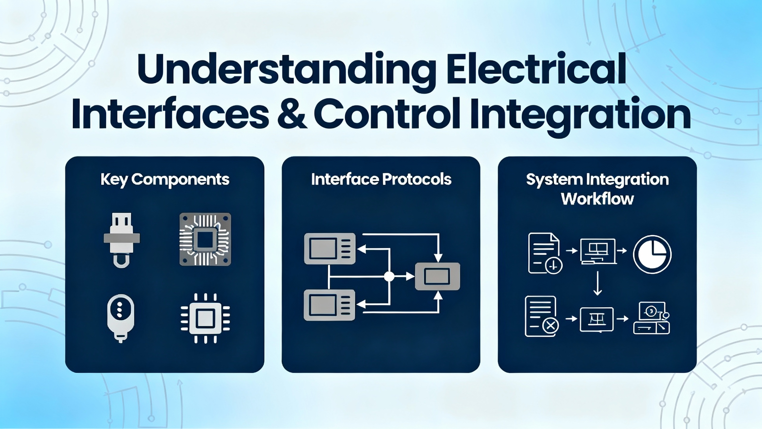
Electrical Interfaces and Control Integration
Even the best sensing technology fails if the signals do not reach the controller cleanly. Several sources, including Dynapar, Motion Control Tips, Timken, Maxon, and HEIDENHAIN, emphasize electrical interface as a core selection variable.
For incremental encoders, common output types include TTL, HTL, open collector, push-pull, and differential line-driver signals. TTL outputs suit low-voltage, relatively short runs in quieter electrical environments. HTL outputs, typically associated with higher supply voltages such as 10 to 30 V, are better suited for longer cables and noisier industrial conditions. Open-collector outputs offer flexible voltage compatibility but require pull-up resistors and can be more prone to interference and slower transitions. Differential RS-422 line-driver outputs transmit complementary pairs, for example A and ─Ć, B and B╠ä, and optionally Z and Z╠ä. Maxon recommends differential drivers for long runs and positioning applications because they improve noise immunity, sharpen signal edges, and support cable lengths on the order of tens of meters while preserving encoder supply voltage within specification.
Quadrature encoders use channels A and B, displaced by 90 electrical degrees, so that four distinct states can be detected for each physical line on the disk. Motion Control Tips notes that a 100 pulses-per-revolution encoder with quadrature effectively yields 400 countable states per revolution. Many encoders also provide an index or Z pulse once per revolution at a defined mechanical zero, which improves homing accuracy when used with appropriate mounting features.
Absolute encoders communicate position as bits and bytes rather than as simple pulses. Dynapar, HEIDENHAIN, Timken, and Rockwell Automation all refer to common protocols such as SSI, BiSS, CANopen, EtherCAT, Modbus, and various Industrial Ethernet options like EtherNet/IP and Profinet. These interfaces reduce wiring complexity and can carry diagnostics along with position data, but they require that the controller support the protocol with sufficient bandwidth. Suppliers that provide clear documentation and tools for integrating these interfaces with common drives and PLCs simplify the engineerŌĆÖs task and reduce commissioning risk.
In power systems where electrical noise, ground potential differences, and surges are common, careful choice of differential interfaces, shielded cabling, proper grounding, and surge protection on encoder supplies is critical. The Digi-Key forum discussion of encoder failures specifically calls out voltage surges as a likely cause, highlighting the need to treat encoder supply lines with the same respect as any low-voltage control power.
Mechanical Form Factors and Mounting
Encoder selection does not stop at signal type. The physical construction and mounting approach are central to long-term reliability.
US Digital and Timken describe three primary rotary encoder form factors: shafted encoders, modular encoder kits, and hollow-bore encoders. Shafted encoders include internal bearings and a protruding shaft that is coupled to the motor or load, often via a flexible coupling to accommodate misalignment. Encoder kits eliminate the encoderŌĆÖs own bearings and shaft; instead, they provide a base, disk, sensor module, and cover that mount directly on the host shaft, relying on the motorŌĆÖs bearings. This approach can reduce cost and allow higher maximum speed because there are no encoder bearings to limit rpm. Hollow-bore encoders have bearings that surround a central hole; the encoder slides over the existing shaft and is secured with a clamp or tether, making installation compact and tolerant of some shaft runout.
Dynapar and HEIDENHAIN add further mechanical variations, including hollow-shaft, hub-shaft, bearingless, and ring encoders, as well as linear and draw-wire devices. Bearingless encoders, for example, use a sensor and a separate target wheel or ring and can offer high reliability by eliminating internal mechanical wear surfaces, at the cost of more stringent alignment during installation.
Timken and Motion Control Tips remind engineers to account for shaft load ratings and maximum mechanical speed. Exceeding the specified radial or axial load can accelerate bearing wear, while running beyond rated rpm can introduce signal distortion or mechanical failure. In high-speed applications such as spindle drives, conveyors, or turbines, manufacturers often provide charts or guidance to align encoder models with speed ranges and load limits.
Mounting options such as flange, servo, or clamp-style attachments, along with cable exit orientation, need to match the available space and ease of alignment in the machine. Poor mounting is one of the most common root causes of premature encoder failure, alongside power and cabling issues.
Environmental and Reliability Considerations
When encoders fail in the field, the root cause is rarely an abstract specification; it is almost always an environmental or mechanical stress that was underestimated.
DynaparŌĆÖs environmental recommendations, TimkenŌĆÖs selection guidance, and HEIDENHAINŌĆÖs application notes all emphasize evaluating temperature, humidity, contamination, shock, and vibration early in the design. Maxon provides a typical encoder operating temperature range from about ŌłÆ30 ┬░C to +100 ┬░C, which corresponds roughly to ŌłÆ22 ┬░F to 212 ┬░F, but the exact limits vary by model and supplier. Magnetic and capacitive encoders generally tolerate dust and moisture better than optical designs, but every technology has limits.
Ingress protection (IP) ratings indicate how well housing seals keep out dust and liquids. Timken advises at least IP65 for outdoor or washdown environments, and HEIDENHAIN distinguishes sealed encoders for harsh industrial use from exposed encoders for ultra-clean, high-performance applications like semiconductor manufacturing. In chemical or food processing plants, encoders may be exposed to cleaning agents, oils, or corrosive fluids, and stainless steel housings or specially sealed enclosures can dramatically improve life.
The Digi-Key forum discussion of a high-speed rotary encoder shows how vibration, mechanical shock, cable stress, shaft play, and voltage surges dominate failure modes more than internal material wear. The recommended mitigations are familiar to any reliability engineer: control vibration and shock through mechanical design and isolation, ensure motor bearings and shaft alignment are within spec, provide strain relief and routing that prevent cable flex concentration, and protect against electrical disturbances with appropriate surge protection and grounding.
Maxon and Dynapar both underscore the role of signal quality: jitter, pulse length variation, and integrated non-linearity in incremental encoders can all degrade accuracy. Good shielding, grounding, and differential signaling reduce noise-induced jitter. High-quality mechanics and sensing elements improve inherent accuracy and repeatability.
In safety-related or high-availability systems, some suppliers offer redundant feedback devices, dual-channel encoders, or encoders with advanced diagnostics such as cable fault detection and overspeed monitoring. DynaparŌĆÖs work on intelligent encoders shows how fault outputs can tie into PLCs for condition monitoring. When evaluating suppliers, it is worth asking not only for the encoder itself but also for the diagnostic capabilities that support predictive maintenance and reduced total cost of ownership.

Comparing Encoder Technologies at a Glance
The research from multiple manufacturers supports a consistent comparison among the main sensing technologies and output types. The following table summarizes these themes.
| Technology / Type | Key Strengths | Main Limitations | Typical Use Cases |
| Optical incremental | High resolution and accuracy, cost-effective, widely available | Sensitive to dust, oil, moisture, and shock unless sealed; light path must stay clean | General industrial automation, robotics, packaging, CNC when environment is controlled or sealed |
| Optical absolute | Unique code per position, no homing needed after power loss | More complex and costly; environmental constraints similar to other optical encoders | Safety-sensitive or restart-critical machinery, multi-axis coordination |
| Magnetic incremental or absolute | Rugged, tolerant of oil, dirt, and water; avoids many optical disk failures | Generally lower resolution and more signal jitter; sensitive to stray magnetic fields | Heavy industry, outdoor machinery, mining, steel, food and beverage washdown lines |
| Capacitive | Low power, good contamination tolerance, compact designs | Often limited to smaller shafts and lower maximum speeds; fewer off-the-shelf options | Moderately demanding environments where power and size are constrained |
| Resolver / inductive | Naturally absolute, extremely robust, no sensing electronics at rotor | Bulky, higher interface complexity, typically higher cost | Extreme environments, high-reliability motor drives, applications where electronics must be remote |
| Incremental output | Simple pulse counting, excellent for speed and relative position, widely supported | Loses position on power loss; requires homing and external counters | Conveyors, general motor speed control, cost-sensitive axes |
| Absolute output | Reports exact position on demand, even after power cycles; can carry diagnostics | Higher device and integration cost; protocol and controller dependency | Large or heavy axes, safety-critical positioning, systems with limited homing freedom |
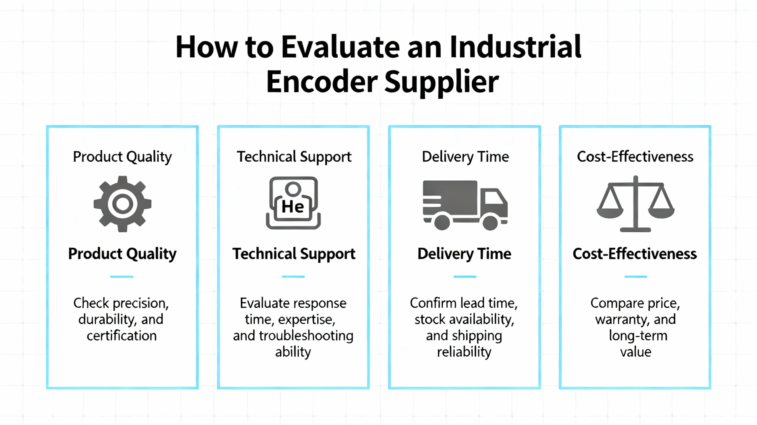
How to Evaluate an Industrial Encoder Supplier
Choosing the right encoder technology is only part of the job. The quality of the supplier and the ecosystem around the encoder significantly influence system reliability and lifecycle cost.
Several themes emerge across resources from Dynapar, Encoder Products Company, HEIDENHAIN, Timken, US Digital, and others.
A strong encoder supplier invests in education and application support. DynaparŌĆÖs knowledge center, US DigitalŌĆÖs white papers, and HEIDENHAINŌĆÖs selection guides demonstrate this model. They provide clear definitions, explain incremental versus absolute, detail interface options like quadrature, SSI, BiSS, and Industrial Ethernet, and walk through examples in robotics, machine tools, and medical technology. This kind of content reflects real engineering depth; it is also invaluable for your own teamŌĆÖs learning.
Another sign of a capable supplier is robust selection tooling and cross-reference support. Encoder Products Company emphasizes online configuration tools, frequency calculators, and wheeled-encoder sizing guides, as well as the ability to cross-reference existing part numbers and deliver replacements or custom variants in reasonable lead times. In a plant with a mixture of legacy encoders, that kind of support can save weeks of troubleshooting and redesign.
Environmental and mechanical breadth also matter. Dynapar describes hazardous-area encoders, heavy-duty designs for mining and pulp and paper, and specialized models for off-highway vehicles and ski lifts. HEIDENHAIN highlights encoders for vacuum environments and ultra-precise angle measurement with accuracy down to fractions of an arcsecond and resolutions up to 29 bits. Suppliers with this range tend to have the design and testing infrastructure to support unusual or harsh applications.
Support for modern interfaces and diagnostics is increasingly important. Rockwell Automation, TechBriefs, and several vendors underline the growing role of Industrial Ethernet and protocol-rich absolute encoders. Suppliers that can offer protocol options, integration examples with mainstream PLCs and drives, and encoders with built-in diagnostics such as cable-fault detection and overspeed monitoring make it easier to implement condition-based maintenance and digital twins.
Finally, long-term support and after-sales service are critical. GTEncoderŌĆÖs guidance on choosing suppliers stresses verifying reliability metrics such as mean time between failures and prioritizing vendors that provide strong after-sales and technical support. ManufacturingTomorrowŌĆÖs coverage of Encoder Products Company echoes that message, noting how close technical collaboration upfront improves the odds that the first encoder delivered is the right fit, thereby reducing downtime and rework.
From a power systems reliability standpoint, the best encoder supplier behaves more like a long-term partner than a catalog. They should understand not just the encoder, but the motor, drive, switchgear, and mechanical process it sits within, and they should be prepared to help troubleshoot when a power event or environmental change exposes weaknesses.
A Practical Selection Workflow for Motion Feedback in Power-Dependent Systems
The selection guides from US Digital, Timken, HEIDENHAIN, and others align around a similar workflow, which adapts naturally to facilities where uptime and power quality are central concerns.
The first step is to characterize the world your encoder must live in. US Digital suggests defining the type of motion, speed range, data acquisition system inputs, available power supplies, cable lengths, mounting location, mechanical transmission elements, environmental conditions, expected production volumes, and cost constraints. In a power-critical environment, this also includes understanding how often power disturbances occur, what kind of UPS or surge protection is present, and whether the machine can safely move after a power event.
Once the world is defined, the next step is to choose between rotary and linear encoders based on whether the motion is angular or linear, then to select among optical, magnetic, capacitive, or alternative technologies based on resolution needs and environmental factors. If the application is in a relatively clean enclosure and demands high precision, optical encoders may be preferred. If the environment is dirty, wet, or subject to mechanical abuse, magnetic or capacitive encoders are often better suited.
The third step is to decide between incremental and absolute feedback. Guides from HEIDENHAIN, Rockwell Automation, and TechBriefs all converge on similar advice: incremental encoders are appropriate when cost and speed control are the main drivers and homing is acceptable. Absolute encoders are recommended when the system must know its position immediately on power-up and cannot move freely to find a reference. Distance-coded and multi-turn absolute designs are useful compromises when a small homing motion is possible but full-range homing is not.
After choosing the fundamental type, the engineer needs to specify resolution. ManufacturingTomorrow and Maxon recommend deriving resolution from application geometry, speed, and control requirements, rather than simply choosing the highest number available. For instance, a robotic arm assembling very small components may require tens of thousands of counts per revolution, whereas large boxes on a conveyor may be adequately served with much lower resolution. Overspecifying resolution can raise costs and push signal frequencies into ranges that stress cabling, interfaces, and controller inputs.
Mechanical integration comes next. This includes selecting shafted, modular, or hollow-bore construction, verifying shaft diameters and load ratings, choosing mounting styles that can be aligned reliably, and checking that encoder dimensions fit within the available space without forcing compromises on cable routing or strain relief.
Electrical integration should then be validated. Timken and Motion Control Tips emphasize matching encoder output types to controller inputs, ensuring that supply voltages, allowable cable lengths, and noise immunity are adequate. That may mean choosing differential line-driver outputs, shielded twisted-pair cables, and proper grounding and surge suppression, especially in electrically noisy or power-dense plants.
Finally, the design should be reviewed for environmental margins and lifecycle support. That means confirming IP ratings against actual dust and moisture exposure, checking temperature ratings against worst-case ambient and self-heating conditions, and verifying that shock and vibration ratings exceed realistically expected levels. It also means selecting a supplier that can provide documentation, diagnostics, and long-term availability, so that encoder failures do not become a chronic reliability bottleneck.
FAQ
Do I really need absolute encoders on every inverter-driven motor?
Not necessarily. Sources such as HEIDENHAIN, Rockwell Automation, and Timken consistently recommend incremental encoders for applications where only speed or relative position matters and where homing moves on startup are acceptable. Absolute encoders make more sense where the machine cannot safely move to a home switch after power loss, where restart time is critical, or where heavy or hazardous motion must resume from a known position immediately. In many plants, a mix of incremental encoders on simpler drives and absolute encoders on critical axes offers the best compromise.
What is the most common cause of encoder failure in harsh industrial environments?
The research and field commentary summarized in the notes strongly suggest that external factors dominate. The Digi-Key forum discussion of a high-speed encoder points to vibration, mechanical shock, cable strain, and voltage surges as the primary drivers of failure rather than internal contact wear. Manufacturers like Dynapar, Timken, and Maxon also stress that exceeding environmental ratings for temperature, contamination, and mechanical loading, along with poor mounting and inadequate cabling practices, are major contributors. In practice, keeping encoders within their specified vibration, shock, temperature, and IP limits and treating power and signal wiring carefully has more impact on reliability than any single component choice.
How high should encoder resolution be before it stops adding value?
Several sources, including Maxon, ManufacturingTomorrow, and TechBriefs, caution against assuming that more counts are always better. Incremental encoder resolution can range from a handful of counts per revolution up to several tens of thousands of counts, with quadrature decoding multiplying effective states. Absolute encoders often provide single-turn resolution in the range of many bits. The key is to align resolution with the smallest motion increment that matters in your process and with the capability of your control electronics to process the resulting signal frequency. Once resolution is finer than the mechanical repeatability of the system or the noise floor of the process, additional counts mostly increase cost and complexity without improving performance.
From a power-system specialistŌĆÖs standpoint, encoders are not just accessories bolted onto motors. They are core reliability components that connect electromechanical reality to digital control. When you pair the right encoder technology with a capable supplier and integrate it thoughtfully into your power and protection architecture, motion feedback becomes as dependable as your best UPS, and your entire system becomes easier to control, diagnose, and trust.
References
- https://www.encoder.com/encoder-applications
- https://docs.broadcom.com/docs/AV00-0128EN
- https://www.dynapar.com/knowledge/
- https://www.lakelandengineering.com/choosing-the-right-dynapar-encoder-for-your-application/
- https://www.motioncontroltips.com/understanding-encoders/
- https://www.plantengineering.com/encoder-selection-guide/
- https://www.timkenencoders.com/en-us/how-to-choose-the-right-encoder-for-your-application
- https://anaheimautomation.com/blog/post/encoders-guide?srsltid=AfmBOoqzQCDFaoVryb75OiEuC8XBjJUhOlB5BBdxaf01u5I-raey0_WB
- https://cdn.automationdirect.com/static/press/encoder-white-paper.pdf
- https://control.com/technical-articles/different-types-of-motor-encoders-Commonly-used-in-automation/


 Videos
 News
News Applications


Leave Your Comment