In modern power systems, gas turbines sit right on the fault line between old baseload thinking and the new world of flexible, lowŌĆæcarbon generation. HighŌĆæefficiency combinedŌĆæcycle plants routinely approach about 60% electrical efficiency according to the U.S. Department of Energy, and combined heat and power (CHP) configurations can use roughly 65ŌĆō80% of the fuelŌĆÖs energy when waste heat is recovered, as documented in the EPAŌĆÖs CHP technology catalog. At the same time, simpleŌĆæcycle gas turbines can start in around twenty minutes and ramp aggressively, making them ideal for backing up wind and solar, as noted in ASME work on the energy transition.
None of that performance is possible without sophisticated control systems. Every MW of dispatchable capacity, every percentage point of efficiency, and every avoided trip depends on how well the turbineŌĆÖs control system senses reality, makes decisions, and actuates valves, vanes, and breakers. When I am brought in to assess power system reliability for industrial and commercial facilities, apparent ŌĆ£mechanical problemsŌĆØ with gas turbines often trace back to control and instrumentation issues: a misŌĆæcalibrated inlet guide vane, a noisy exhaust temperature sensor, or a poorly tuned load controller.
This article takes a practical look at gas turbine control systems for the energy sector, drawing on published work from ASME, the Department of Energy, EPA, MDPI, OEM technical papers, and fieldŌĆæoriented guidance from industry specialists. The goal is to connect advanced control concepts with the dayŌĆætoŌĆæday decisions plant engineers and project teams must make to keep turbines safe, efficient, and ready for a lowerŌĆæcarbon grid.
Gas Turbines and Their Role in TodayŌĆÖs Power Mix
A gas turbine is an internal combustion engine operating on a continuous Brayton cycle. Ambient air enters the compressor, is pressurized to high velocity and temperature, mixed with fuel in the combustor, and burned at temperatures often well above 2,000┬░F. The hot gas expands through turbine stages, spinning blades that drive both the compressor and an electrical generator. The U.S. Department of Energy describes typical turbine gas temperatures in modern plants around 2,300┬░F, while critical metal components can safely tolerate only roughly 1,500ŌĆō1,700┬░F, which is why intensive cooling schemes are needed.
There are two major classes of stationary gas turbines. HeavyŌĆæframe units are physically large, with lower pressure ratios typically below about 20 and very high power outputs. Aeroderivative machines are derived from aircraft engines, more compact, with pressure ratios above roughly 30 and strong efficiency and partŌĆæload performance, as DOE and EPA sources describe. In CHP applications, combustion turbine sizes from about 1 to 40 MW per unit are common for industrial campuses and institutional users, with utility units extending well above 200 MW.
Energy efficiency and emissions are the reason gas turbines matter so much in the energy transition. EPAŌĆÖs CHP catalog and DOE technical material show that simpleŌĆæcycle turbines typically achieve about 20ŌĆō35% electric efficiency, and many modern units are in the 25ŌĆō40% range. When the turbineŌĆÖs highŌĆætemperature exhaust, often about 850ŌĆō1,100┬░F, is captured in a heatŌĆærecovery steam generator and used to drive a steam turbine or provide process heat, overall fuel utilization can reach about 65ŌĆō80%. ASME analysis of combinedŌĆæcycle plants documents net efficiencies above 60% on a lower heating value basis for heavyŌĆæduty gas turbines. When natural gas replaces coal, the combination of higher efficiency and cleaner fuel can cut carbon dioxide emissions per MWh by roughly half, and in some ASME modeling cases by around 60%, while reducing sulfur oxides, particulates, and many local pollutants.
Operationally, gas turbines provide flexibility that many coal and nuclear plants cannot. ASME and OEM case studies show large turbines in the 300ŌĆō400 MW class that can start in about twenty minutes and operate at more than 40% efficiency in simpleŌĆæcycle mode, making them ideal peakers to firm variable renewables. GE and Siemens material on HA and HL class turbines emphasize their ability to ramp quickly in combinedŌĆæcycle service while maintaining very high efficiency. The flip side is that frequent cycling and fast loadŌĆæfollowing stress the turbine and its control system far more than steady baseload operation, which is exactly where advanced control becomes indispensable.
What a Gas Turbine Control System Actually Does
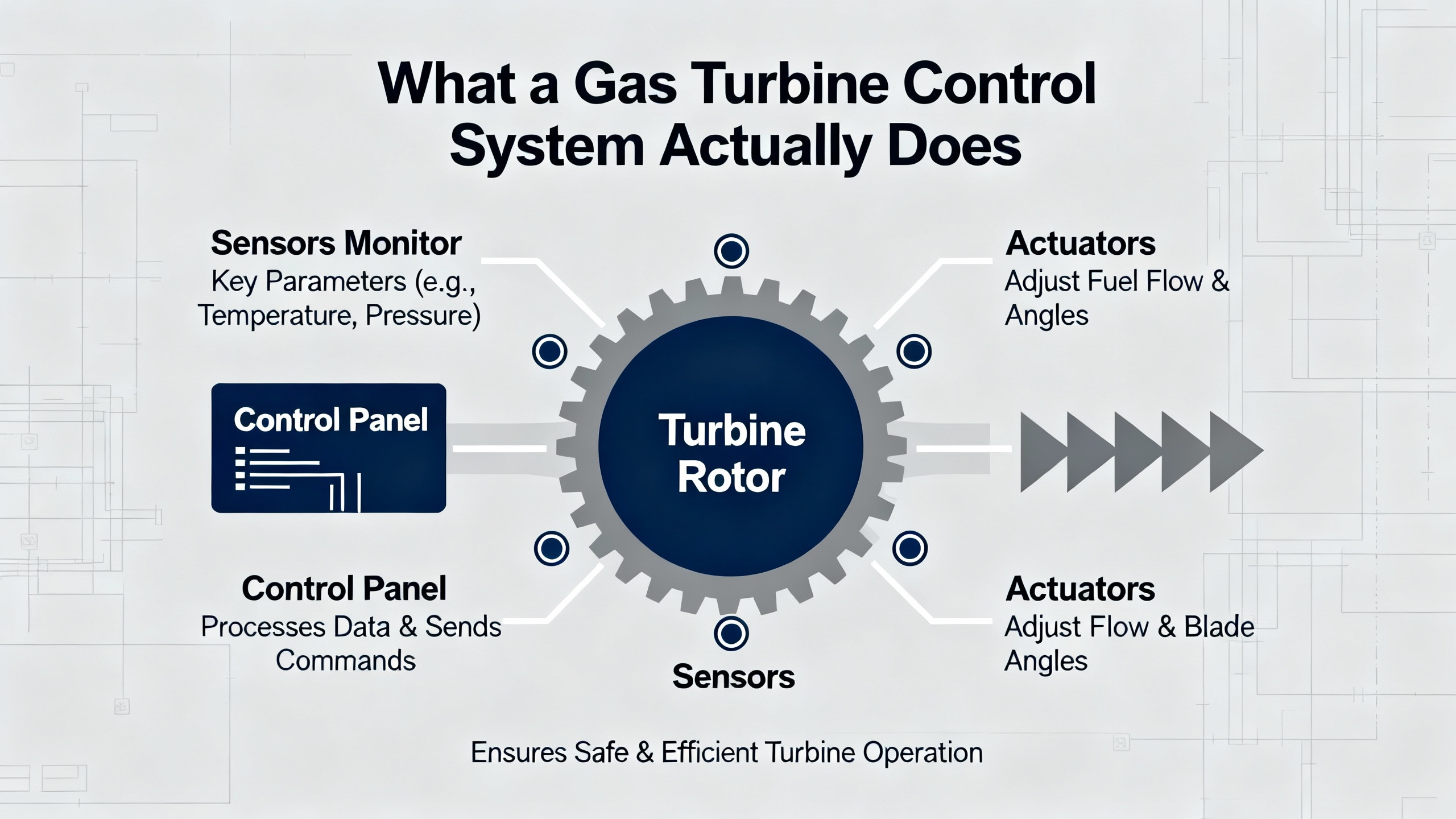
A gas turbine control system is an integrated hardwareŌĆæsoftware platform that monitors, regulates, and protects the turbine and its generator using realŌĆætime sensor data. Unisys and NYU technical overviews describe these systems managing turbine startup and shutdown, load and speed control, exhaust and blade temperatures, fuel and air flows, and protective functions such as overspeed and low lubeŌĆæoil pressure trips. In a modern power plant, the turbine control typically interfaces with the plantŌĆÖs distributed control system (DCS), humanŌĆōmachine interfaces (HMI), and supervisory control and data acquisition (SCADA) systems so that operators can see a coherent picture and execute coordinated actions.
Along the compressorŌĆōcombustorŌĆōturbineŌĆōgenerator chain, the control system commands inlet guide vanes to regulate air mass flow, schedules fuel to achieve the desired firing temperature and load, modulates variable guide vanes where fitted, and controls generator excitation so that voltage and reactive power stay within limits. It also executes tightly choreographed startup and shutdown sequences, monitors vibration, lubeŌĆæoil and fuel pressures, and exhaust composition, and triggers alarms or trips when conditions cross predefined thresholds.
The core objectives behind all this logic are straightforward to state but difficult to achieve in practice. Safety comes first: preventing overspeed, overpressure, fire, and hotŌĆæsection damage. Reliability and availability are next: keeping forced outages low and recovering gracefully from disturbances. Efficiency and emissions follow closely, since fuel and compliance costs dominate lifecycle economics. Finally, flexibility and ramping capability have become critical, because turbines increasingly compensate for wind and solar swings, a theme reinforced in MDPI research on energyŌĆæefficient gas turbine control.
Core Control Functions Along the Chain
Classical descriptions of industrial gas turbine control, such as those summarized in MDPIŌĆÖs review of GT controllers, identify several interlinked functions. During startup, a starting controller manages initial fuel for ignition and acceleration from standstill to a defined runŌĆæup speed. A runŌĆæup controller then brings the machine to synchronous speed while staying within thermal and mechanical limits. Before reaching full load, a frequency and load controller balances speed and active power output to maintain grid frequency, assisted by an automatic speed regulator. A maximum load controller caps active power to stay within turbine and generator ratings. Temperature controllers regulate turbine inlet and exhaust temperatures using fuel flow and inlet or variable guide vanes, both to preserve efficiency and to limit thermal stress. A final protective function limits maximum turbine inlet temperature during malfunctions or rapid load swings.
Combustion and emission control sit inside those loops. Modern dry lowŌĆæNOx combustors and diffusion combustors with water or steam injection rely on tight regulation of fuelŌĆōair ratio and temperature. EPA CHP documentation and IPIECA analysis of openŌĆæcycle gas turbines note that emission control strategies range from DLN combustion to water or steam injection and selective catalytic reduction in the exhaust. The control challenge is to keep NOx, CO, and unburned hydrocarbons within regulatory limits while avoiding combustion instability or flameout and without sacrificing too much efficiency.
On the generator side, TurbineLogicŌĆÖs material on generator controls explains how automatic voltage regulators manage excitation to hold generator terminal voltage, while frequency control functions keep electrical frequency within tight bounds despite load changes. Synchronization control ensures the generatorŌĆÖs voltage, frequency, and phase match the grid before breaker closure. Faulty sensors, communication failures between devices, or software defects can lead to voltage or frequency excursions, oscillations in output, and nuisance trips, which is why robust design and thorough testing of these functions are so important.
An additional nuance appears in practical combustion mode management. A detailed control.com discussion of GE DLNŌĆæI combustion systems describes how mode transfers between different combustion regimes are keyed to exhaust temperature references rather than fixed MW values. If an operator sets a preŌĆæselected load that leaves the exhaust temperature hovering exactly at the transfer threshold, the turbine can chatter between modes, causing instability. That thread, written from handsŌĆæon troubleshooting experience, underlines a recurring theme: the control logic is only as good as the inputs, calibrations, and operating practices surrounding it.
Control Architectures: Analog, DCS, PLC, and OEM Platforms
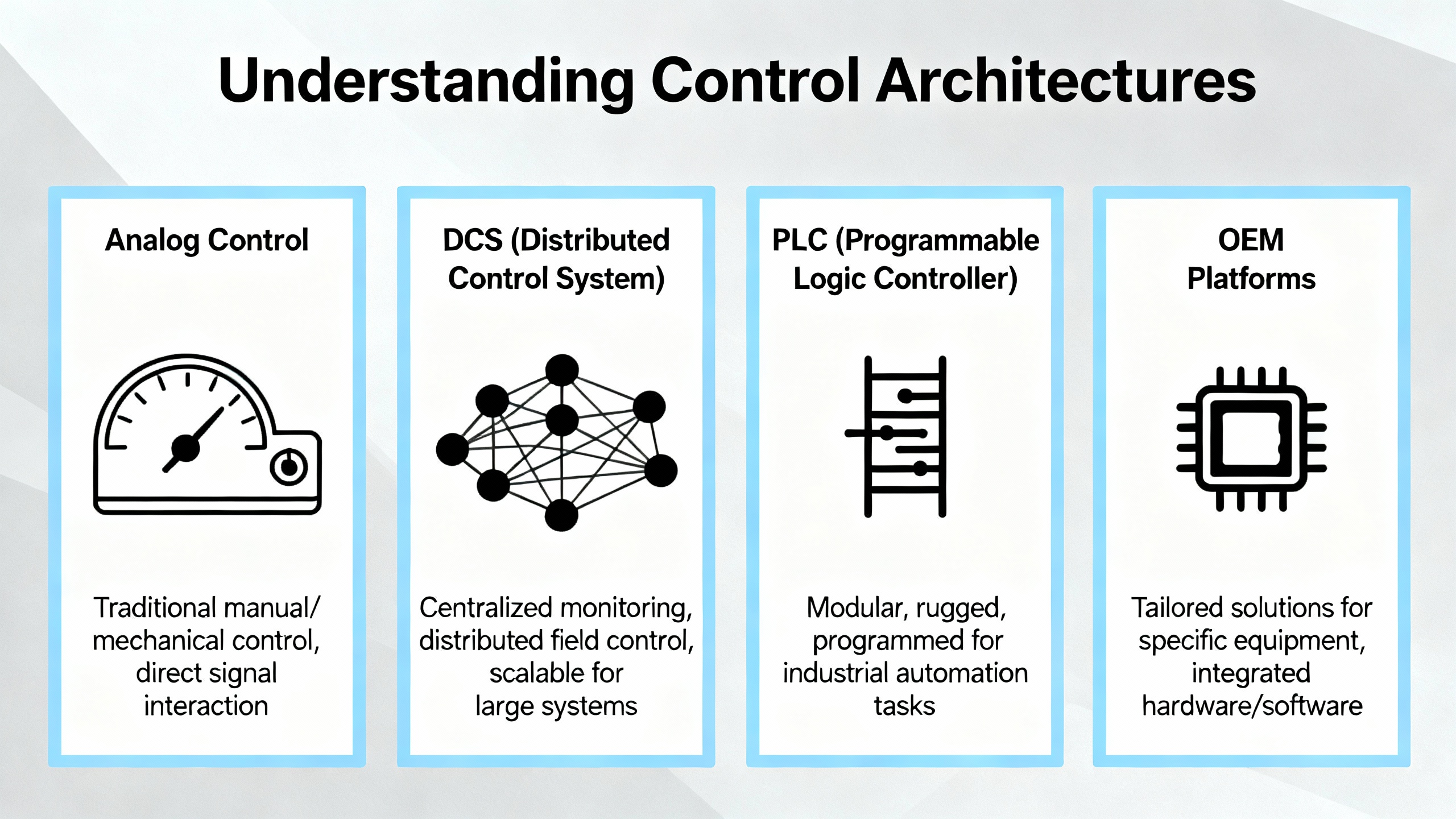
Gas turbine control architectures in the field span several generations. Unisys classifies them into analog systems, digital control systems, programmable logic controllers, and turbineŌĆæspecific OEM controllers.
Analog systems use mechanical relays, analog sensors, pneumatic devices, and standalone PID controllers. Decades of operation in harsh environments have proven their basic reliability, and many remote or older installations still run on this technology. However, these systems offer limited diagnostics, almost no native remote access, and poor integration with digital plant systems. Troubleshooting often depends on a shrinking pool of highly experienced technicians who can interpret charts and relay logic.
Digital control systems, or DCS platforms, centralize multiple subsystems such as temperature, vibration, fuel, and balance of plant into a common environment. With modern HMIs, realŌĆætime trend displays, automated startup sequences, alarm management, and data historians, DCS architectures are particularly well suited to complex plants and fleetŌĆæwide monitoring. They also support redundancy at multiple levels, from controllers and networks to I/O modules, which can deliver high availability when correctly engineered.
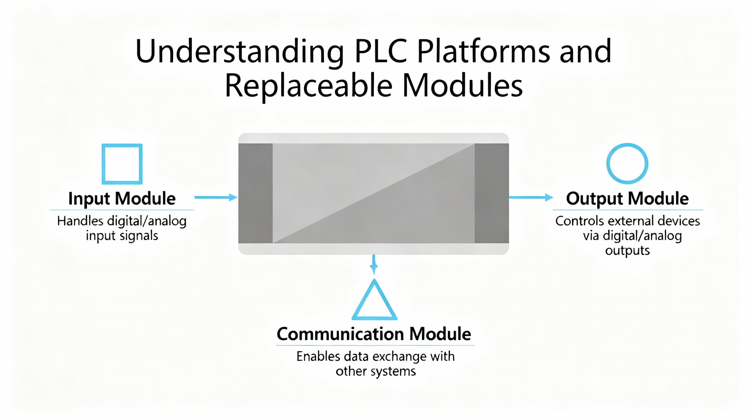
Programmable logic controllers provide another digital option. PLCs are modular industrial computers, typically programmed with ladder logic or structured text, that excel in fast, deterministic I/O handling and flexible configuration. For smaller turbines or retrofits where a fullŌĆæscale DCS would be excessive, PLCŌĆæbased systems can combine highŌĆæspeed control with good integration into existing plant systems, especially when paired with thirdŌĆæparty HMIs.
OEMŌĆæspecific turbine controllers, such as GEŌĆÖs Mark V and Mark VIe families, SiemensŌĆÖ T3000, or ABBŌĆÖs Symphony Plus, are built around the exact characteristics of particular turbine designs. They provide preŌĆæengineered sequences for startup, load management, and protection; deep integration with OEM diagnostic and predictive analytics tools; and builtŌĆæin support for redundant processors and safetyŌĆæintegrity functions. Unisys notes that some GE Mark VIe configurations include separate safetyŌĆærated controllers certified to Safety Integrity Levels defined in IEC 61508, ensuring that emergency shutdown and other highŌĆæintegrity functions remain independent of the main control logic.
A concise way to compare these architectures is shown here.
| Architecture | Typical applications | Key strengths | Main limitations |
| Analog | Older and remote turbines, simple units with limited automation needs | Proven reliability, simplicity, immunity to some cyber threats | Poor diagnostics, limited integration, reliance on specialist skills |
| DCS | Large combinedŌĆæcycle plants, complex industrial sites | Unified view of plant, advanced HMI, scalable redundancy, plantŌĆæwide analytics | Higher capital cost, more complex engineering and lifecycle management |
| PLCŌĆæbased | Small to midŌĆæsized turbines, retrofits, packaged units | Flexibility, fast I/O, costŌĆæeffective, good thirdŌĆæparty integration | Requires careful design to match turbine dynamics; less ŌĆ£outŌĆæofŌĆæboxŌĆØ turbine expertise |
| OEM turbine controller | New heavyŌĆæduty or aeroderivative units, safetyŌĆæcritical installations | TurbineŌĆæspecific logic, certified safety, vendor diagnostics and tuning tools | Vendor dependence, constrained customization, need to align with plantŌĆæwide standards |
In practice, large plants often deploy hybrid architectures. A GE Mark VIe or Siemens turbine controller may handle core turbine logic, while a plant DCS supervises HRSGs, balance of plant, and overall coordination. Smaller sites may rely on PLCŌĆæbased turbine control that sends key data into a central SCADA system. From a reliability perspective, what matters most is that the chosen architecture offers sufficient diagnostic depth, redundancy, and integration for the plantŌĆÖs risk profile and staffing.
Key Loops and Strategies in Modern Turbine Control
Startup, RunŌĆæup, and Load Control
Reliable startup is where many control problems reveal themselves. MDPIŌĆÖs review of gas turbine control points out that the startup and runŌĆæup phases must handle nonlinear, multiŌĆætimescale dynamics while respecting exhaust and metal temperature limits. Starting controllers must admit enough fuel to light off and accelerate the rotor without causing overŌĆætemperature or flameout. RunŌĆæup controllers need to bring the machine smoothly to synchronous speed despite changing compressor behavior and turbine clearances as components warm up.
Once synchronized, a frequency and load controller governs power output. In gridŌĆæconnected service, the turbine typically operates in a loadŌĆæcontrol mode where it shares system load according to droop settings or receives setpoints from a plant dispatcher. Under islanded or weakŌĆægrid conditions, speed control becomes more prominent, with the turbine acting as a frequency leader. MDPI notes that frequent and rapid loadŌĆæfollowing, driven by variable renewable output, tends to reduce efficiency, increase thermal and mechanical stresses, and shorten component life. Control strategies that temper ramp rates and keep temperatures within tight bands can significantly mitigate these effects, even if they occasionally sacrifice a little responsiveness.
Temperature, Stress, and Emission Management
Temperature control is the heart of both performance and blade life. DOEŌĆÖs advanced turbine program raised allowable turbine inlet temperatures by roughly 300┬░F compared with older designs, up to about 2,600┬░F, thanks to advanced alloys and improved cooling. That extra temperature translates directly into higher thermal efficiency, especially in combinedŌĆæcycle plants, but only if the control system manages cooling air and firing temperature precisely.
Practical temperature control relies on a combination of fuelŌĆæflow scheduling, inlet and variable guide vane positioning, and limiting functions that override operator commands if turbine or exhaust temperatures approach safe limits. The MDPI article describes temperature controllers that regulate exhaust and blade temperatures during load swings, as well as dedicated limiters that cap turbine inlet temperature during malfunctions. Tuning these loops is delicate: overly conservative limits sacrifice output and efficiency, while aggressive settings risk cracking blades or damaging combustors.
Emission control adds another dimension. EPA and IPIECA documents describe three broad options for NOx control: dry lowŌĆæNOx combustion, water or steam injection into the combustor, and selective catalytic reduction in the exhaust. DLN systems rely heavily on precise fuel staging and lean premixing, which makes them particularly sensitive to ambient conditions, fuel composition, and tuning. The control.com troubleshooting discussion illustrates how poor calibration of inlet guide vane position or fuel control valves, or tuning performed at extreme ambient conditions, can lead to unstable mode transfers in DLNŌĆæI systems. Once again, accurate instrumentation and careful adherence to OEM tuning procedures are foundational.
OpenŌĆæCycle, CombinedŌĆæCycle, and CHP Control Nuances
OpenŌĆæcycle gas turbines, where exhaust heat is not recovered, are mechanically simpler but can be difficult to operate efficiently. IPIECAŌĆÖs analysis of openŌĆæcycle gas turbines notes that even modern aeroderivative units with electric efficiencies in the 33ŌĆō43% range have much higher greenhouse gas emissions per MWh than combinedŌĆæcycle or CHP plants, simply because so much heat leaves in the exhaust. Controls on these machines often prioritize fast starts and ramping for peaking and backup duty, and the control system must manage ambientŌĆædriven performance swings. When ambient temperature rises above the ISO reference of about 59┬░F, turbine power and efficiency fall, prompting many operators to adopt inlet air chilling or evaporative cooling. GEŌĆÖs GERŌĆæ3620 guidance on inlet cooling shows that wellŌĆædesigned evaporative or mechanical cooling can add roughly 5ŌĆō25% to turbine power on hot days, but only if the cooling systems are tightly integrated with turbine surge and temperature protection logic.
CombinedŌĆæcycle and CHP plants add steam systems and heatŌĆærecovery equipment to the mix. The EPA CHP catalog emphasizes that combustion turbines in these configurations achieve very high overall fuel utilization, but only when the control system balances electric output with thermal demand. Controls must coordinate gas turbine load, HRSG steam production, and steam turbine or processŌĆæsteam valves, ensuring that steam pressures stay within limits and that downstream users receive the heat they need. This coordination complicates ramping: aggressive gas turbine load changes can create steam pressure excursions or thermal fatigue in heatŌĆærecovery components, so combinedŌĆæcycle control philosophies often moderate turbine ramps or preŌĆæemptively adjust duct firing and steam bypasses.
Advanced Control and Digitalization
For decades, proportionalŌĆæintegralŌĆæderivative controllers have dominated industrial gas turbine control. MDPIŌĆÖs survey acknowledges that classical PI and PID loops are simple to tune, robust, and inexpensive, but it also points out their limitations when dealing with multivariable interactions, stringent constraints, and aggressive load swings. SteadyŌĆæstate error, limited feedback stability margins, and difficulty enforcing multiple constraints can become serious issues in a renewableŌĆæheavy grid.
To address these challenges, researchers and some advanced plants are exploring model predictive control, fuzzy modified model reference adaptive control, and optimizationŌĆæbased schemes such as whale optimizer algorithms. In broad terms, these methods use predictive models of the turbine and combined cycle to anticipate future states, optimize control actions against multiple objectives, and explicitly enforce constraints on temperatures, stresses, ramp rates, and emissions. MDPI notes that the computational burden and modeling complexity increase significantly when regenerators, intercoolers, and other cycle enhancements are added, but the payoff can be improved efficiency and reduced stress during fast transients.
Alongside new control algorithms, digitalization is transforming everyday operations. Prismecs, USPE, and several controls vendors describe the growing role of dense sensor networks, Industrial Internet of Things platforms, and machine learning in gas turbine fleets. Continuous data collection on temperatures, pressures, fuel flows, vibration, and performance indices feeds analytics that can detect anomalies long before alarms appear. Call GTC India emphasizes that trending key performance indicators and analyzing patterns enable more accurate maintenance scheduling and refined control strategies. Unisys and NYU highlight builtŌĆæin diagnostics and prognostics in platforms like GEŌĆÖs Mark V and Mark VIe, which analyze operating data to support conditionŌĆæbased maintenance.
From a reliability advisorŌĆÖs perspective, this trend is welcome, but only when combined with disciplined use. Data and dashboards do not improve reliability by themselves. Plants that benefit the most are those where engineers and operators routinely review trends, investigate subtle degradations, and close the loop by updating maintenance and control settings, rather than treating the turbine controller as a sealed black box.
Reliability, Maintenance, and Cybersecurity of Control Systems
In many plants I have reviewed, the practical limit on gas turbine reliability has not been blade life or combustor wear; it has been avoidable trips and misŌĆæoperations driven by control and instrumentation weaknesses. Several sources in the research notes converge on the same maintenance themes.
Call GTC India stresses regular, scheduled inspections of control cabinets, actuators, and sensors, with a focus on catching wear, corrosion, leaks, and loose terminations before they trigger trips. Keeping cabinets clean and free of dust and debris is critical because contamination degrades insulation, interferes with cooling, and affects sensor accuracy. Routine calibration and functional testing of sensors, transmitters, and control loops maintain measurement integrity so that control algorithms react to reality instead of noise.
Operator training repeatedly emerges as a central factor. GTC IndiaŌĆÖs guidance and NYUŌĆÖs discussion of Mark V systems both assume wellŌĆætrained staff who understand system behavior, recognize abnormal trends, and respond correctly to alarms and combustion mode changes. Where operators simply acknowledge alarms without investigating, minor deviations grow into serious incidents. In contrast, control.com contributors analyzing DLN combustion problems insist on rich timeŌĆæseries data and narrative context before drawing conclusions, underscoring how expertise and data must work together.
On the maintenance strategy side, AX Control advocates strongly for conditionŌĆæbased maintenance rather than purely timeŌĆæbased schedules. TimeŌĆæbased approaches may replace components long before their useful life ends, wasting both parts and outage windows. ConditionŌĆæbased maintenance uses performance and condition data to determine the ŌĆ£prime timeŌĆØ for replacement, a strategy that AX Control argues is more effective for gas turbines that operate under varying loads and ambient conditions. Gathering accurate performance data, understanding wear patterns, and then planning replacements around those insights allows plants to get full value from components without running them to failure.
Mechanical fouling and aging interact tightly with control. IPIECAŌĆÖs discussion of openŌĆæcycle turbines notes that compressor fouling from airborne contaminants gradually reduces power output and efficiency, sometimes limiting overall oil and gas production capacity. Regular offline water washing and frequent inlet filter changes can restore several tenths of a MW on a 21 MW aeroderivative unit and save up to about 4,000 tons of carbon dioxide per year. However, plants can only justify and time these cleanings effectively when their control systems provide trustworthy performance baselines and trends that show how power output and heat rate are drifting.
Redundancy and safety are the final pillars. Unisys describes dense sensor networks feeding safety instrumented systems designed to IEC 61508, with independent logic solvers executing highŌĆæintegrity shutdown functions such as overspeed and fire response. Automated emergency shutdown systems are engineered to fail to the safest state, usually a rapid trip and fuel shutoff, if power or control logic is lost. For critical facilities in sectors such as oil and gas or chemicals, redundant controllers, power supplies, and communication networks ensure that a single hardware failure does not halt the turbine. The Mark* family of controllers and similar OEM platforms embody this philosophy, but their benefits only materialize if input calibration and wiring integrity are maintained; otherwise, as one control.com contributor put it, ŌĆ£garbage in, garbage out.ŌĆØ
Cybersecurity overlays all of this. Call GTC India notes that keeping control software up to date and applying security patches promptly is essential to protect modern, networked turbine controllers from digital threats. OEM platforms increasingly incorporate hardened architectures and certified cyberŌĆæsecure designs, but these protections are undermined if plants neglect user and access management, remoteŌĆæaccess policies, and patch planning.
From an auxiliary power standpoint, turbine control systems are extremely sensitive to power quality. ShortŌĆæduration voltage sags, harmonics, or DC power interruptions to control and protection circuits can cause spurious trips or misŌĆæoperations just as surely as a process upset. That is why in industrial and commercial power system designs, these controls are typically supplied from conditioned, backedŌĆæup sources with robust power protection. Ensuring that UPS systems, inverters, and auxiliary feeders are themselves reliable and well maintained is therefore a genuine part of gas turbine reliability engineering, not an afterthought.
Controls as Enablers of the Energy Transition
Several of the sources in the research notes address a central question: what role do gas turbines play in a netŌĆæzero future? ASMEŌĆÖs analysis of gas turbines in the energy transition, GE VernovaŌĆÖs commentary on HA turbines, and PowerMagŌĆÖs coverage of HLŌĆæclass plants and hydrogenŌĆæready fleets all point in the same direction. HighŌĆæefficiency combinedŌĆæcycle gas turbines already dominate many new power orders and are likely to remain important for decades because they provide flexible, dispatchable capacity, fast ramping, and relatively low emissions, especially when fired on natural gas instead of coal.
Prismecs and USPE emphasize that modern combinedŌĆæcycle gas turbine plants reaching roughly 60% efficiency use less fuel and emit substantially less carbon dioxide per kWh than typical coal plants at around 33% efficiency. ASMEŌĆÖs numbers suggest that simply switching from coal to natural gas can cut carbon dioxide emissions by about 60% per unit of electricity, even before adding postŌĆæcombustion capture. With carbon capture and storage, gasŌĆæfired plants can push emissions even lower, although this adds process complexity and dynamic constraints that control systems must manage.
Hydrogen and lowŌĆæcarbon fuels are another frontier where controls will be critical. IPIECA notes that manufacturers are developing turbines capable of burning synthetic gas with around 20% hydrogen and eventually up to 100% hydrogen, with dry lowŌĆæemission combustion, and are also exploring ammonia as a hydrogen carrier. PowerMag reports that major OEMs have roadmaps for turbines that can coŌĆæfire substantial hydrogen fractions today and aim for 100% hydrogen capability by around the end of this decade, supported by independent H2ŌĆæreadiness certifications. As the control.com discussion of DLN systems stresses, even modest changes in fuel composition can destabilize premixed combustion if controls are not reŌĆætuned. HydrogenŌĆÖs different flame speed, calorific value, and combustion characteristics will demand more sophisticated fuel property measurement, adaptive fuel scheduling, and perhaps more advanced control algorithms than classical PIDs alone.
OpenŌĆæcycle gas turbines in particular face pressure to improve. IPIECAŌĆÖs analysis points out that their lower efficiency leads to higher emissions per MWh than combinedŌĆæcycle or CHP alternatives, yet they remain common in remote and offshore applications where space and complexity are constrained. Here, controlŌĆæenabled technologies such as inlet air chilling, wasteŌĆæheat recovery through compact organic Rankine cycles, and optimized loading of multiple smaller units can materially reduce fuel use and emissions.
At the distributed level, EPAŌĆÖs CHP work and various industrial case studies show that appropriately sized turbineŌĆæbased CHP plants provide both reliable power and useful heat to refineries, chemical complexes, and campuses. These facilities can reach overall energy utilizations approaching 80% and can support local resilience. Their control systems must balance electric export, local demand, and heat flows, especially where turbines back up or complement other onŌĆæsite generation such as gas engines or renewables.
Practical Guidance When Specifying or Upgrading Turbine Controls
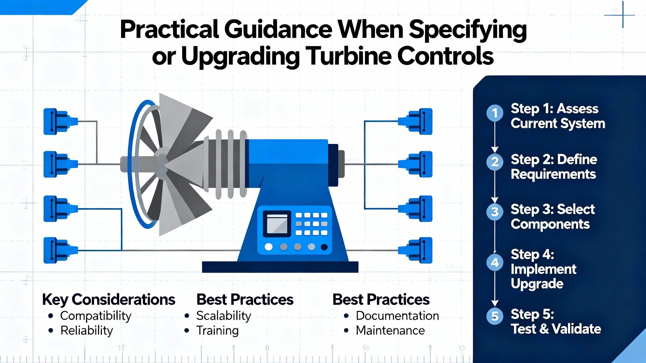
For project teams working on new gas turbine plants, the most effective approach is to treat turbine control requirements as part of the electrical and energy strategy from day one, not as a vendor black box. Clarify up front the expected operating mode, whether baseload, midŌĆæmerit, or frequent cycling; the need to follow renewables; and any plans for future fuels such as hydrogen blends. These choices drive control platform selection, redundancy requirements, and the level of sophistication needed in algorithms and diagnostics. Ensure that turbine controls integrate cleanly with the plant DCS, generator protection relays, gridŌĆæinterconnection schemes, and auxiliary power and UPS systems, so that signals and permissions remain consistent across the plant.
In retrofit scenarios, the challenge is usually to migrate from aging analog or firstŌĆægeneration digital controllers to platforms that offer better diagnostics and integration without introducing new risks. Unisys and NYU case material suggests that moving to modern OEM controllers, DCS, or hybrid PLC solutions can significantly enhance safety and reliability, but only if done with thorough planning. That includes detailed asŌĆæbuilt documentation, careful I/O mapping, likeŌĆæforŌĆælike functional testing, and staged commissioning that allows the plant to validate new control logic under controlled conditions.
For operating plants, the most practical improvement is often cultural rather than purely technical. GTC IndiaŌĆÖs emphasis on regular calibration, cabinet housekeeping, and operator training, AX ControlŌĆÖs advocacy for conditionŌĆæbased maintenance, and the control.com insistence on detailed data for troubleshooting all point in the same direction. DayŌĆætoŌĆæday reliability improves when teams systematically document assets and strategies, review trends, investigate anomalies early, and treat the turbine control system as an instrumented process that can be optimized, not merely as an automatic box to be left alone until it trips.
Short FAQ
How is a gas turbine control system different from the plant DCS?
The turbine control system is responsible for the realŌĆætime safety and performance of the gas turbine and its generator: fuel and air management, temperature and speed control, combustion stability, protection, and startup and shutdown sequences. The plant DCS supervises broader systems such as HRSGs, steam turbines, balance of plant, water systems, and sometimes multiple units. In many modern plants the turbine controller handles millisecondŌĆælevel decisions for the turbine itself, while the DCS sends highŌĆælevel load commands, coordinates steam and auxiliary systems, and provides the main operator interface.
Do smaller industrial or commercial plants really need advanced turbine controls?
Smaller plants may not need model predictive control or complex optimization, but they still benefit from modern digital platforms with good diagnostics, trending, and secure remote access. EPAŌĆÖs CHP catalog and industrial case studies show that even turbines in the 1ŌĆō40 MW range can achieve high availability, often above 90ŌĆō95%, when controls are well maintained and integrated with conditionŌĆæbased maintenance. At that scale, a single unplanned outage can have major business consequences, so investments in robust control hardware, accurate sensors, and operator training usually pay off quickly.
What should I prioritize if I can only fund one major improvement?
If budget limits you to one major step, focus on improving measurement quality and data use. That may mean recalibrating critical sensors, upgrading key transmitters, fixing cabinet environments, and implementing disciplined trending and analysis. As control.com experts often remind operators, the controller can only act on the data it sees, and ŌĆ£garbage inŌĆØ produces ŌĆ£garbage out.ŌĆØ Once you trust your measurements and trends, you can make informed decisions about when to clean compressors, replace components, retune combustion, or justify a larger control platform upgrade.
In the end, advanced gas turbine control is not about clever algorithms alone; it is about building a coherent chain from reliable auxiliary power, through clean and calibrated instrumentation, into wellŌĆædesigned control logic, and finally to operators who understand both the turbine and the grid it serves. From the standpoint of an industrial and commercial power system specialist, that chain is what turns a gas turbine from a fragile, highŌĆætech machine into a durable, flexible asset that can underpin resilient, lowŌĆæcarbon power for decades.
References
- https://www.energy.gov/fecm/how-gas-turbine-power-plants-work
- https://energy.mit.edu/publication/comparative-study-on-energy-rd-performance-gas-turbine-case-study/
- https://www.epa.gov/sites/default/files/2015-07/documents/catalog_of_chp_technologies_section_3._technology_characterization_-_combustion_turbines.pdf
- https://wp.nyu.edu/mind/2023/08/03/an-introduction-to-gas-turbine-technology-and-gas-turbine-control-systems/
- https://www.ipieca.org/resources/energy-efficiency-compendium/open-cycle-gas-turbines-2022
- https://asmedigitalcollection.asme.org/gasturbinespower/article/146/10/101008/1197217/Gas-Turbine-s-Role-in-Energy-Transition
- https://callgtcindia.com/blog/best-practices-for-maintenance-and-operation-of-gas-turbine-controls
- https://petrotechinc.com/how-gas-turbines-work/
- https://prismecs.com/blog/how-gas-turbines-are-transforming-the-future-of-energy-production
- https://www.uspeglobal.com/blog/70406-unlocking-efficiency-the-future-of-natural-gas-turbines-in-energy-generation


 Videos
 News
News Applications


Leave Your Comment