ICS Triplex Trusted systems sit in the part of a plant where my clients have the least tolerance for surprises: emergency shutdowns, turbine protection, burner management, and power system interlocks. When you start talking about ŌĆ£compatible modulesŌĆØ and upgrades in that environment, you are no longer just doing a parts swap. You are altering the behavior of a highŌĆæintegrity safety platform that may be tied to UPSŌĆæbacked power, critical inverters, and highŌĆæconsequence loads.
This guide walks through how to think about ICS TriplexŌĆæcompatible modules, how to plan upgrades around a Trusted triple modular redundant (TMR) system, and how to integrate additional I/O or subsystems without compromising safety, availability, or power quality. The focus is practical: what a power and controls engineer actually has to check, who has to be involved, and how to avoid the subtle pitfalls that show up years later as nuisance trips or unexplained downtime.
ICS Triplex Trusted TMR in PowerŌĆæCritical Facilities
ICS Triplex, now under the Rockwell Automation umbrella, has spent over four decades delivering safety and critical control systems into highŌĆærisk sectors such as oil and gas, refining, petrochemical, chemical, and power generation. According to industry overviews from specialist distributors, thousands of ICS Triplex systems are in service worldwide, handling emergency shutdown, fire and gas detection, burner management, turbomachinery and compressor control, and general process control. That field history matters, because compatibility and upgrade decisions are not being made in a vacuum; they are being made on a platform that is already deeply embedded in highŌĆæhazard operations.
The Trusted system is ICS TriplexŌĆÖs flagship safety PLC platform. As described by independent technical summaries, it is built on a Triple Modular Redundancy architecture. Three processing channels run the same logic in parallel, with voting and integrity checks to deliver very high fault tolerance, deterministic scan times, and detailed diagnostics. In practice, that means a single hardware fault or even certain types of transient errors do not automatically translate into a process trip. The system can continue to operate safely while flagging degraded channels for maintenance.
This architecture is a natural fit for powerŌĆæcritical facilities. In an industrial plant, a safety shutdown of a turbine, generator, or highŌĆæenergy drive is sometimes necessary; a spurious trip can be extremely expensive. A wellŌĆæimplemented TMR system gives you both sides of that equation: high probability that demanded trips will occur when required, and high resilience against false trips driven by hardware faults, electrical noise, or marginal power.
Originally ICS Triplex delivered turnkey, fully integrated safety and control systems. Today the Trusted system is typically engineered and integrated by a network of certified independent integrators and thirdŌĆæparty firms who work with Rockwell AutomationŌĆÖs literature and tools. That ecosystem is valuable when planning moduleŌĆælevel changes, because compatibility questions are often answered in vendor release notes, technical bulletins, and integrator knowŌĆæhow rather than in generic PLC documentation.
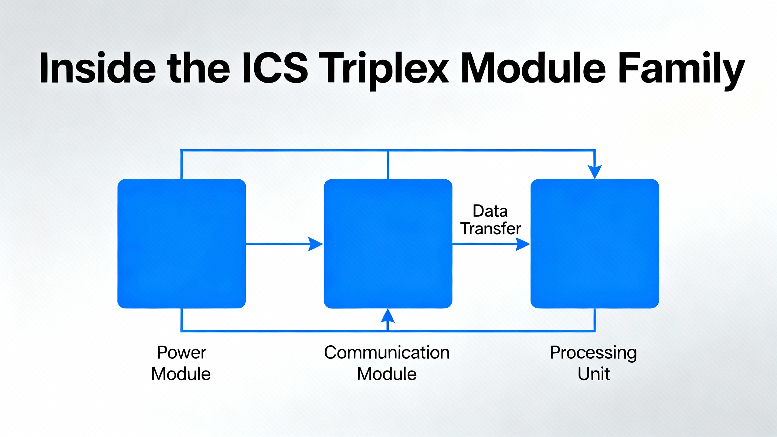
Inside the ICS Triplex Module Family
To make sensible decisions about ŌĆ£compatible modules,ŌĆØ you need a clear picture of the building blocks you are touching. Public module overviews from integrators and stocking distributors give a useful highŌĆælevel map of common Trusted hardware.
At the center is the T8100 Trusted TMR Processor. It executes the control logic across all three TMR channels, performs voting and integrity checks, and enables rapid fault detection. Around it sit communication adapters such as the T8153 and T8151C, which provide highŌĆæspeed, faultŌĆætolerant networking between racks and subsystems. These interfaces are designed to preserve redundancy across channels and keep latency low, which is vital when you are coordinating trips, permissives, and alarms across multiple cabinets.
For process safety expansion, the T8311 Expander Interface and T8300 Process Safety PLC Module allow the system to scale across distributed I/O without losing safety integrity. This is the path large plants take when they extend an existing Trusted installation to cover additional units, substations, or new generator bays.
On the field side, a set of input and output modules provides the realŌĆætime process connection. Digital input modules such as the T8403 and highŌĆædensity T8850 gather contact status from interlocks, pressure switches, and protection relays, with the T8850 packing forty channels with line monitoring and diagnostic feedback. Analog input modules such as the T8431 acquire continuous process values; summaries emphasize their use in realŌĆætime data gathering with TMRŌĆæbacked input validation to catch sensor deviations or faults quickly.
Digital output modules such as the T8461 and T8461C operate in the 24ŌĆō48 V DC range and are used for deterministic, safe switching of field devices such as shutdown valves and alarm horns. The T8451, referenced in field discussions, is another digital output module used alongside them in many installations. For rotating equipment, the T8442 Speed Monitor Module continuously supervises shaft speed and can trigger alarms or shutdowns when anomalies are detected, using its integration with the TMR logic to safeguard turbomachinery.
Supporting all of this, the T8191 PLC I/O Communications Module acts as the backbone for data exchange between I/O and the processor, with an emphasis on deterministic transfers and minimized transmission errors. The T8270 rackŌĆæmount fan assembly manages airflow and cooling for installed modules, mitigating overheating as a reliability risk.
A simplified view of selected Trusted modules and their roles is shown below.
| Module | Type | Typical role | Notes for upgrades |
| T8100 | TMR processor | Executes safety and control logic across three channels with voting and integrity checks | Any change affects system behavior globally; firmware and application changes demand rigorous testing and approval |
| T8153 / T8151C | Communication interface | HighŌĆæspeed, faultŌĆætolerant networking between racks and subsystems | Integration point for additional racks or subsystems; care needed when introducing new network segments |
| T8311 | Expander interface | Links I/O expansion racks | Key when extending I/O count; physical and firmware compatibility are critical |
| T8300 | Process safety PLC module | Process safety logic in expanded architectures | Often used when building out new safety functions alongside an existing Trusted core |
| T8403 | Digital input | Collects discrete field inputs with TMRŌĆæbacked validation | Firmware consistency between redundant modules is a common concern in upgrades |
| T8431 | Analog input | Acquires realŌĆætime analog signals from the field | Firmware/build variations between cards appear frequently in older systems |
| T8461 / T8461C | 24ŌĆō48 V DC digital output | Safe, deterministic switching for critical actuators like shutdown valves | Key interface to power protection equipment and trip coils; output voltage and load matching must be verified |
| T8451 | Digital output | General digital output module used in Trusted systems | Firmware and base ID variations have been reported in field systems and must be evaluated before mixing |
| T8442 | Speed monitor | Supervises rotary equipment speed and trips on anomalies | Strongly tied to turbomachinery protection schemes and power reliability |
| T8850 | 40ŌĆæchannel digital input | HighŌĆædensity DI with line monitoring and diagnostics | Useful where panel space is constrained but DI counts are high |
| T8191 | I/O communications | Backbone for I/OŌĆōCPU data exchange | Affects timing and determinism; integration changes should be extensively tested |
| T8270 | Rack fan assembly | Controls cooling and airflow across modules | Directly influences longŌĆæterm reliability, particularly in highŌĆæload or poorly ventilated rooms |
Distributors also list additional modules such as T8800, T9100, T9300, T9191, T9310ŌĆæ02, T8310, T9451, T9852, and T9110. Even where public information does not spell out every function, the key point for integration planning is that you are dealing with a mature ecosystem of modules and spares, not a single monolithic controller.
What ŌĆ£CompatibilityŌĆØ Means in an ICS Triplex Environment
Compatibility in a Trusted system goes far beyond matching connector styles. From a safety and powerŌĆæreliability standpoint, there are at least four dimensions to consider: firmware and build revision alignment, electrical and powerŌĆæsupply fit, communication and integration behavior, and safety and compliance posture.
Firmware and Build Revision Alignment
A real example discussed on the Control.com technical forum highlights the firmware challenge. An engineer working on an ICS Triplex Trusted TMR system reported a configuration with a T8110B processor module at firmware ID 352000, with two different builds in circulation (Build 100 and Build 100.7A). The same system used T8431 analog input modules with firmware ID 352790, but with Build 037 on one card and Build 130 on another. The T8403 digital input module was at firmware ID 352870 Build 037. For the T8451 digital output module, the engineer saw modules with base firmware ID 352930 Build 130 and others with base firmware ID 353100 Build 0037.
The core concern was straightforward and extremely practical: what happens when redundant modules in the same pair run different firmware or even different base firmware IDs? Will failover behave correctly, will diagnostics remain trustworthy, and are such combinations even supported by the vendor? The engineer explicitly asked what the latest recommended firmware and build were for each module and whether differing builds were safe in redundant configurations, looking for a formal technical note from ICS Triplex or Rockwell Automation.
This example illustrates why module compatibility decisions in a Trusted system cannot be based on generic PLC guidance alone. Firmware and build interactions are defined in vendor documentation such as Rockwell Automation technical notes and ICS Triplex release bulletins. The public excerpt from an ICS Triplex maintenance training manual underscores that the company treats its detailed documentation as proprietary, with information subject to change and no warranty that a single document will cover all hardware and software variations. Taken together, that means you need an explicit, projectŌĆæspecific answer from the vendor or an authorized integrator when you plan to mix firmware builds within redundant pairs or across a rack.
The working practice I see in wellŌĆærun facilities is conservative. Whenever possible, redundant modules within a pair are kept on the same base firmware ID and build, with upgrades staged in a way that mirrors Trusted system recommendations from Rockwell Automation literature. When a mismatch is unavoidable, for example because of a spare card shipped at a newer firmware, the change is treated as an engineering modification: vendor notes are requested and reviewed, the combination is tested in a nonŌĆæcritical environment, and results are documented before exposing the configuration to safetyŌĆæcritical loads.
Electrical and PowerŌĆæSupply Compatibility
From a powerŌĆæsystems perspective, the Trusted rack is just another nonŌĆælinear DC load hanging off your UPS and power distribution. In reality it is much more than that, because any brownout, inrush, or ripple that upsets the PLC can trip large generators, feeders, or critical industrial processes.
General PLC maintenance guidance from sources like PDF Supply and eWorkOrders highlights several points that apply directly to ICS Triplex installations. PLCs commonly run on 24 V DC power supplies, with smaller systems drawing on the order of a few amps and large controllers drawing tens of amps. Technicians are advised to verify that AC input voltage matches the power supply setting, to confirm that DC output is within the specified range, and to check AC ripple on DC lines using a meter set to a low AC range. Excess ripple can cause memory and microprocessor issues, leading to unexplained faults. They are also advised to measure actual operating current and compare it to nameplate ratings for both the PLC and the power supply.
Translating that into a Trusted environment, a module upgrade is an ideal moment to reŌĆævalidate power margins and UPS sizing. When you add highŌĆædensity I/O such as a T8850, or expand with additional racks via a T8311 expander, your 24 V DC load will increase. Your UPS or DC supply must not only supply the steadyŌĆæstate current; it must also support any inrush behavior and keep the voltage within an acceptable window during transfer events or faults. In plants where ICS Triplex racks are fed from inverters tied to DC battery strings, that may mean revisiting inverter ratings, branch current limits, and cable sizing.
BatteryŌĆæbacked memory is another compatibility dimension. Maintenance guides emphasize the role of CPU battery indicators that show whether RAM and EPROM backup is healthy. In many controllers, including TrustedŌĆæclass systems, if the battery falls below threshold, a power interruption can erase configuration or program data. Firms like PDF Supply advise treating a red or flickering battery indicator as a trigger for replacing the pack with the exact voltage and current type. In a TMR safety system that relies on deterministic behavior during and after power events, coordinating battery health with UPS strategy is part of compatibility planning, not an afterthought.
Communication and Network Integration
Modern PLCs and I/O modules are not islands. Articles from Industrial Automation Co, Empowered Automation, and Maple Systems all stress the importance of robust communication protocol support and modular architectures: EthernetŌĆæbased networks, Modbus, Profibus, OPC UA, and other protocols that integrate PLCs with HMIs, SCADA, MES, and enterprise systems.
The GE IS420PUAAH1A discrete input module, discussed in a Moore Industries context, is a good example of the type of module you might integrate around a Trusted system rather than directly onto its backplane. It is a 24 V DC discrete input module with eight input channels, response times under 5 milliseconds, and a wide operating range from approximately ŌłÆ40┬░F to 158┬░F at 5% to 95% nonŌĆæcondensing humidity. It is designed for realŌĆætime monitoring and control with low energy consumption around 5 W, supports industryŌĆæstandard communication protocols such as Modbus and Ethernet, and carries CE, UL, and RoHS approvals.
If you are augmenting a Trusted safety core with nonŌĆæsafety PLCs or remote I/O subsystems, modules of this class can be connected over standard networks. The Trusted system continues to handle highŌĆæintegrity safety functions, while external PLCs or I/O blocks handle nonŌĆæsafety automation or local control, exchanging data through SCADA or controllerŌĆætoŌĆæcontroller links. Compatibility in this sense is about ensuring that communication architectures and protocols are well chosen, network topologies are robust, and redundant communication paths exist where needed, as recommended in integration articles from Mochuan and JHFoster.
What you cannot do safely is assume that any Ethernet or ModbusŌĆæcapable module will integrate seamlessly with a Trusted installation. You still have to design the communication interfaces, manage address mapping, and test time behavior under normal and degraded network conditions.
Safety, Cybersecurity, and Standards
ICS Triplex Trusted systems are deployed in applications that must meet strict safety and regulatory targets. Maintenance and integration bestŌĆæpractice documents from firms like RL Consulting emphasize standards such as IEC 61131ŌĆæ3 for programming structures, NFPA 79 for industrial electrical safety, UL 508A for control panel construction, and ISA/IEC 62443 for cybersecurity in industrial systems. Other PLC feature overviews point to ISO 13849ŌĆæ1 and IEC 62061 for safetyŌĆærelated control systems.
These standards do not name ICS Triplex directly, but they shape the environment in which Trusted modules must operate. If you replace a module, introduce a thirdŌĆæparty I/O subsystem, or change communication paths, you must verify not just electrical fitness but also the impact on safety functions and cybersecurity. ConsultingŌĆæSpecifying EngineerŌĆÖs guidance on industrial control system replacement highlights the value of a current state assessment and architecture selection that explicitly address cybersecurity goals and align with frameworks such as NIST SP 800ŌĆæ82 and ISA/IEC 62443.
From a safety integrity standpoint, the safest approach is to keep highŌĆæintegrity safety instrumented functions on certified Trusted modules and to treat external or thirdŌĆæparty modules as nonŌĆæsafety, even if they are robust and wellŌĆæspecified. From a cybersecurity standpoint, segmentation between safety PLC networks and other plant networks should be maintained, with clear boundaries and defenseŌĆæinŌĆædepth applied around any new communication interfaces.
Planning Module Integration and Upgrades Around a Trusted Core
Because ICS Triplex Trusted systems often sit at the center of a plantŌĆÖs safety architecture, the right way to think about module upgrades is as a mini ICS replacement project, not as a patchwork of part swaps. Methodologies described by ConsultingŌĆæSpecifying Engineer and JHFoster for complex ICS and PLC commissioning map very well onto this space.
A good project starts with clear objectives. Are you addressing obsolescence of a specific module type, for example replacing aging T8403 digital inputs with newer units or adding T8850 highŌĆædensity cards to free panel space? Are you extending coverage to new process units or power feeders by adding racks through T8311 expanders and T8300 modules? Are you trying to integrate new power protection functions, such as additional generator protection relays, into the Trusted system? Or are you mainly trying to clean up mismatched firmware builds and adŌĆæhoc additions from years of piecemeal work?
Once objectives are defined, a current state assessment follows. CSEŌĆæMagŌĆÖs guidance on ICS replacement calls for documenting existing architectures, data flows, communications, hardware, software, and documentation, including known vulnerabilities and single points of failure. Applied to ICS Triplex, that means identifying every cabinet where Trusted modules are installed, listing module types and part numbers, recording firmware and build revisions, capturing network topologies via T8153 and T8151C interfaces, and documenting what each I/O point actually does in the process, especially where it interfaces with UPS, inverters, and protective relays.
For powerŌĆæcritical applications, I recommend explicitly mapping which safety functions and interlocks are fed from UPSŌĆæbacked power and which are not. That mapping will guide decisions about where to add redundancy, where to install new I/O, and how to test behavior under simulated power disturbances.
Stakeholder engagement is equally important. Integrated control and safety systems touch operations, maintenance, instrument and electrical engineering, IT or OT cybersecurity teams, and often plant management. JHFosterŌĆÖs case study of a large bakery that integrated PLCs from thirtyŌĆæfive different equipment manufacturers into a single SCADA system shows how complex multiŌĆævendor automation can become. Even though that example was not specific to ICS Triplex, the lesson holds: changes to a central safety PLC ripple across HVAC, utilities, production lines, and power systems.
With objectives, current state, and stakeholders aligned, you can develop a realistic plan and schedule. That plan should define which modules will be replaced or added, how firmware alignment will be handled, how many separate outages or cutovers will be required, and what test procedures will prove system behavior at each stage. ICS replacement projects described in industry literature often span years; a module upgrade project on a Trusted system is smaller, but the same discipline pays off.
Using External or ThirdŌĆæParty Modules Around a Trusted Core
In many plants, the strategy for ICS Triplex ŌĆ£compatibilityŌĆØ is to keep the Trusted hardware as the safety and critical control core and to integrate additional PLCs or I/O islands for nonŌĆæsafety and auxiliary automation. When done well, this approach lets you modernize sections of the plant or add new features without disturbing proven safety logic.
External I/O modules such as the GE IS420PUAAH1A illustrate what to look for in modules that will sit around the safety core. That particular device offers eight discrete input channels, fast response under 5 milliseconds, and a wide ambient temperature range from approximately ŌłÆ40┬░F up to 158┬░F, with humidity tolerance from 5% to 95% nonŌĆæcondensing. It runs on 24 V DC with a modest power draw around 5 W and supports standard communication protocols such as Modbus and Ethernet, with high isolation resistance and approvals from bodies such as CE and UL.
Those attributes matter for several reasons. The wide temperature and humidity range, coupled with isolation and robust construction, means the module can live in harsh environments similar to those where Trusted racks are deployed. The low power consumption simplifies UPS and power supply sizing when adding distributed panels. Standard protocols allow integration through SCADA, data concentrators, or gateway PLCs without resorting to custom drivers. Certifications and RoHS compliance help satisfy corporate engineering and environmental requirements.
The most effective pattern I see in critical power and process plants is to let ICS Triplex Trusted handle safety trips, hard interlocks, and other highŌĆæintegrity functions, while external PLCs and I/O handle optimization, data logging, and nonŌĆæsafety automation. The two layers exchange information over wellŌĆædefined boundaries. That way, module compatibility questions on the safety side remain within the Trusted family, while external hardware can evolve more rapidly using mainstream PLC and I/O platforms, provided they are properly isolated and integrated.
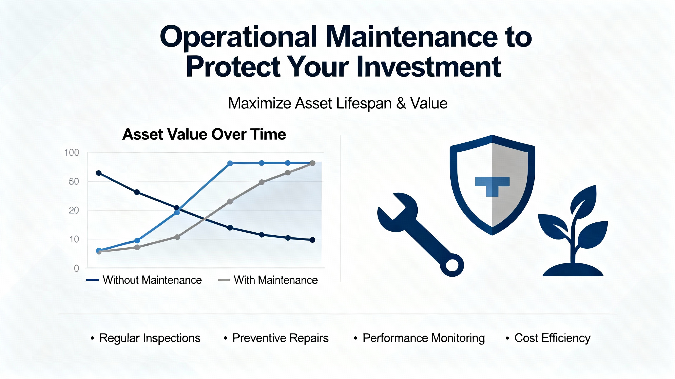
Operational Maintenance to Protect Your Investment
Integration and upgrade work is only part of the story. The longŌĆæterm health of ICS Triplex modules and their surrounding infrastructure depends on disciplined maintenance that respects both control and power realities.
Maintenance guides from PDF Supply, eWorkOrders, and RL Consulting converge on several recurring themes. Regular backups of PLC programs and configuration data are essential, stored on reliable media and protected from humidity, extreme temperatures, and electromagnetic interference. In a Trusted environment, that includes backups of safety logic, I/O configurations, and any applicationŌĆælevel diagnostics, with version control and clear records of change.
Program functionality should be tested periodically using builtŌĆæin diagnostics. Recommended practices include reloading the software, running selfŌĆætests that exercise logic and I/O, and reviewing reports of input and output points, timer and counter presets, configuration parameters, and logged errors. In a TMR system, those tests should confirm not only that each channel performs correctly, but also that voting and fault handling behave as expected when channels are inhibited or simulated faults are applied.
FrontŌĆæpanel LEDs and diagnostic indicators are simple but powerful tools. Guides note that a steady power indicator typically reflects a healthy supply, while dark or flickering LEDs point to supply or wiring issues. Fault indicators that briefly light at startup provide a quick check of controller selfŌĆætests. Battery status LEDs on CPU modules are designed to warn when backup power for memory is degraded. In the context of a safety PLC, those indicators should be part of a formal walkdown routine, not an occasional glance when something goes wrong.
Electrical inspections complement these checks. Technicians are advised to verify that AC supply voltage matches controller and power supply settings, that DC outputs, often at 24 V DC, sit within manufacturer tolerances, and that AC ripple on DC lines remains below specified limits. Measuring input and output current confirms that supplies are not overloaded and that wiring and breakers are correctly sized. For ICS Triplex racks fed from UPS systems or inverters, these checks provide early warning before a load step or utility disturbance exposes a weakness.
Physical connections deserve the same attention. Over time, vibration, thermal cycling, and maintenance activity can loosen terminal screws, I/O module connections, communication cables, and rack hardware. Best practice is to inspect and reŌĆætorque connections periodically, especially in highŌĆævibration areas such as turbine galleries or near large motors. Some facilities go further and interface vibration detectors to PLCs so that excessive vibration can be alarmed and correlated with increased maintenance activity.
Environmental controls round out the picture. Heat, humidity, dust, and airborne contaminants degrade electronics over time. Maintenance articles recommend keeping PLCs and I/O modules free of dust, using suitable enclosures, and cleaning or replacing ventilation filters as they clog, based on actual dust loading rather than arbitrary intervals. They also advise keeping manuals, tools, and papers off the tops of enclosures to avoid blocking airflow. For ICS Triplex systems, where modules such as the T8270 manage rack cooling, ensuring unobstructed airflow and clean filters directly extends module life and reduces random faults.
Finally, configuration management and spares strategy tie everything together. RL Consulting and PDF Supply both stress the importance of maintaining an upŌĆætoŌĆædate inventory of PLCs, including make, programming type, last backup date, and the equipment each controller drives. For ICS Triplex specifically, distributors note a broad ecosystem of modules and spares. Facilities that operate Trusted systems reliably tend to stock critical spares such as CPU boards, power supplies, key I/O modules, and even complete standby racks for the most critical applications, with documented locations and periodic checks to ensure firmware on spares remains compatible with installed hardware.
FAQ
Can I safely mix firmware builds on redundant ICS Triplex modules?
Field reports, such as the Control.com discussion of T8110B, T8431, T8403, and T8451 modules with differing firmware and build identifiers, show that mixed builds do exist in the wild. However, the engineer in that case was concerned enough to request formal guidance from ICS Triplex technical support and to ask for a technical note on firmware compatibility. Rockwell Automation and ICS Triplex documentation, including release notes and maintenance manuals, are clear that details can change and that not all hardware and software variations are covered in any one document. In practice, the only defensible approach for safetyŌĆærelated redundant modules is to consult vendor documentation or an authorized integrator for your exact firmware combinations, and to align redundant pairs on the same base ID and build wherever possible, validating behavior in a controlled test before exposing the configuration to live plant risk.
How do I justify upgrading modules that still appear to work?
From a maintenance standpoint, reliability and lifecycle risk often justify proactive replacement before outright failure. RL Consulting notes that structured maintenance helps identify obsolescent components early so that retrofits can be planned instead of rushed. If an ICS Triplex module is still functioning but is at an older firmware level, lacks diagnostics available in newer variants, or is approaching the end of vendor support, upgrading it during a planned outage can be much less risky than waiting for a failure and making emergency decisions. For safety systems tied to power production or critical loads, including UPSŌĆæbacked feeders and generators, that argument is even stronger because emergency work typically occurs at the worst possible time from a powerŌĆæsystem stability perspective.
Where should I start if documentation for my Trusted system is incomplete?
Many legacy safety systems suffer from missing or outdated documentation. The current state assessment approach described by ConsultingŌĆæSpecifying Engineer is a good starting point. Build an inventory of all ICS Triplex modules and racks, recording part numbers, firmware revisions, network connections, and the field devices they serve. Gather whatever drawings and logic printouts exist. CrossŌĆæcheck this information with plant operators, maintenance technicians, and any integrators who have worked on the system. From there, engage ICS Triplex support or a certified integrator to fill in gaps, confirm module compatibility, and help plan upgrades. The confidential and proprietary nature of ICS Triplex maintenance manuals means you should expect to work closely with these partners rather than reverseŌĆæengineering the system on your own.
As a power system specialist, I treat ICS Triplex Trusted systems as part of the protection and reliability backbone, right alongside UPS systems, inverters, and protective relays. When you view compatible modules and upgrades through that lens, the priorities become clear: respect the safety architecture, validate firmware and electrical compatibility carefully, use external I/O and PLCs around the Trusted core instead of inside it for nonŌĆæsafety tasks, and back the whole arrangement with disciplined maintenance and documentation. Done that way, module changes stop being a source of risk and become an opportunity to raise both safety integrity and power system resilience.
References
- https://www.empoweredautomation.com/best-practices-for-implementing-automation-plc-solutions
- https://www.mochuan-drives.com/a-news-best-practices-for-integrating-plc-controllers-into-industrial-systems
- https://id.mooreplc.com/ICS-Triplex_c13
- https://www.machautotech.com.au/complete-guide-to-plc-systems-design-modification-and-integration/
- https://www.csemag.com/mapping-out-the-key-elements-for-an-ics-replacement/
- http://www.efesotomasyon.com/Allen_Bradley_rockwell/Integrated%20Architecture%20Brozine%20-%20Page%206.pdf
- https://maplesystems.com/10-things-to-consider-when-choosing-new-plc/?srsltid=AfmBOooAOoTwzVZFCJv5X7VVeKtXt_vSYWCD8wdwCuX9Uwg6pOObYeBD
- https://pacificblueengineering.com/integrating-plcs-with-plc-experts/
- https://rlconsultinginc.com/best-practices-for-maintaining-custom-plc-systems/
- https://www.zk-yyds.com/test-author/


 Videos
 News
News Applications


Leave Your Comment