Why GE Relay Equivalents Matter For Power Reliability
In UPS plants, inverter strings, and industrial switchgear, General Electric relays often sit right at the heart of your protection and control schemes. When one of those devices fails or the original GE part number becomes hard to source, the temptation is to ŌĆ£drop in whatever looks closeŌĆØ from a catalog.
In power systems work, that is where reliability problems begin. A relay that looks similar on the outside but does not truly match the GE original in function, coil interface, load capability, or environmental performance can cause nuisance trips, burned contacts, welded outputs, and in the worst case, a failure to trip when you most need protection.
From generalŌĆæpurpose relays discussed in application notes by manufacturers such as GEYA, Omron, and Asia Dragon Electric, through to protective devices described in utility documents like ISO New EnglandŌĆÖs generator protection modeling guidelines and EasyPowerŌĆÖs protective relay basics material, the message is consistent. You must treat relay selection as an engineering task, not a cosmetic match.
Over many field retrofits on inverter cabinets, static transfer switches, and generator controls, I have learned to treat ŌĆ£equivalent to a GE relayŌĆØ as a precise technical statement. ŌĆ£EquivalentŌĆØ has to mean that the replacement behaves the same in your system electrically, thermally, mechanically, and from a safety standpoint, not just that it shares a similar coil voltage or footprint.
This guide walks through how to think about GE relay equivalents in a structured way and how to use general relay best practices to pick compatible options when the original is no longer available.
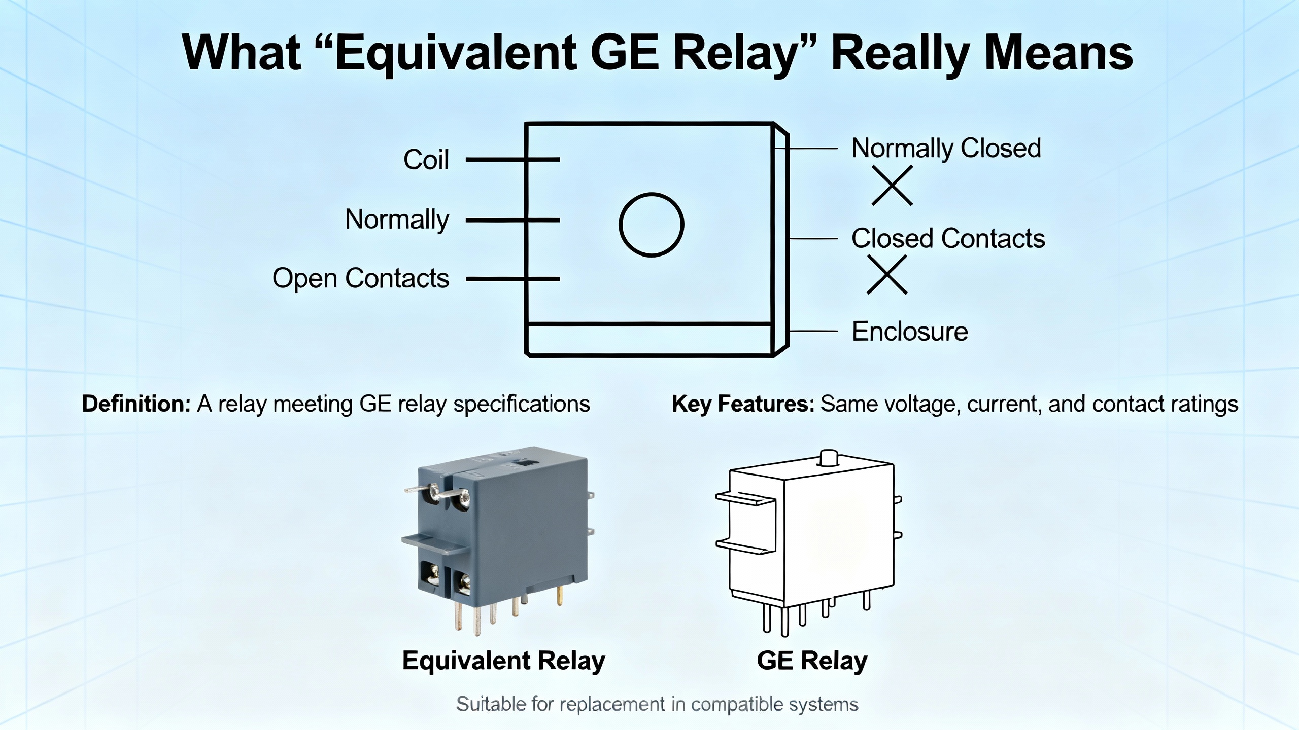
What ŌĆ£Equivalent GE RelayŌĆØ Really Means
When you replace a GE relay with a different model, even from another manufacturer, you are making a design decision. In practice, an equivalent relay has to align on several dimensions at once.
You can think of true equivalence along these lines.
| Equivalence dimension | What must align with the GE relay | Why it matters in real equipment |
| Function | GeneralŌĆæpurpose control, timing, or protective role | A GE protective relay that supervises faults cannot be treated like a simple onŌĆōoff control relay. |
| Coil interface | Coil voltage, AC or DC type, resistance, and allowable overvoltage | Misapplied coil ratings cause nonŌĆæoperation, overheating, or burnout, as OmronŌĆÖs relay application notes highlight. |
| Contact system | Contact form (NO, NC, changeover), poles, and ratings for the actual load type | The ChinaRelay guidance stresses that using a relay with lower rated current than the load invites overheating and early failure. |
| Load behavior | Resistive, inductive, capacitive, or lamp load, including inrush current and minimumŌĆæload issues | Omron and Pickering show that contact wear and welding are dominated by inrush, arcing, and lowŌĆælevel ŌĆ£dryŌĆØ switching conditions. |
| Mechanical and environmental | Size, mounting style, temperature and humidity range, resistance to dust, vibration, and corrosive gases | Asia Dragon Electric points out that kitchen, industrial, and outdoor environments all demand different relay robustness. |
| Isolation and safety | Dielectric strength, clearance and creepage distances, approvals | In power and UPS equipment, relays are often part of the isolation barrier between control electronics and mains or DC bus. |
| Life and reliability | Mechanical and electrical life under your duty cycle, derating strategy, protection circuits | PickeringŌĆÖs reliability guidance and OmronŌĆÖs durability curves demonstrate that nameplate ratings assume specific test conditions, not worstŌĆæcase field duty. |
Only when you can say ŌĆ£yesŌĆØ across these dimensions is a replacement relay genuinely equivalent to what GE originally intended that device to do.
In practice, there are two broad families of GE relays you will encounter.
One group consists of generalŌĆæpurpose and industrial control relays similar to the general purpose devices described by GEYA and ClinŌĆæEle. These switch coils, contactors, lamps, and logic signals, and they are relatively straightforward to replace if you respect coil, contact, and environmental constraints.
The other group consists of protective relays for generators, transformers, lines, and feeders. Documents such as EasyPowerŌĆÖs protective relay basics and ISO New EnglandŌĆÖs generator protection modeling guidelines, along with GE Vernova manuals like the P64 technical manual, treat these as part of an integrated protection scheme with instrument transformers and trip circuitry. For these, ŌĆ£equivalentŌĆØ quickly becomes a systemŌĆæwide question, not just a part number crossŌĆæreference.
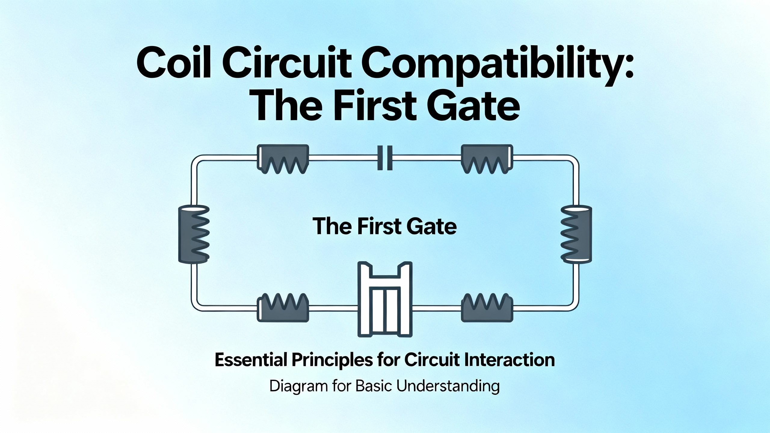
Coil Circuit Compatibility: The First Gate
Every relay has at least two worlds: the lowŌĆæpower coil side and the higherŌĆæpower contact side. Matching the coil side correctly is the first gate any GE replacement has to pass.
Application material from Omron emphasizes that relay ratings always include coil ratings and contact ratings. Coil voltage and frequency must not exceed the specified AC or DC value, or the relay can suffer abnormal heating, performance loss, and coil burnout. AC coil labels like ŌĆ£AC 100 V 60 HzŌĆØ or ŌĆ£AC 100/110 VŌĆØ are not standardized across manufacturers, so you have to read the catalog carefully and compare it with the actual control voltage.
General guidance from relay manufacturers lines up on several practical points.
Coil voltage and type must match the control source. A 24 VDC coil cannot be driven from a 120 VAC logic bus, and a 120 VAC coil driven from a 24 VDC PLC output will not pull in. When moving away from a GE part, you should measure the actual control voltage under both normal and lowŌĆævoltage conditions, not just assume nameplate values.
Coil resistance defines current draw and pullŌĆæin force. A realŌĆæworld question from an Electronics Stack Exchange user illustrates the risk of ignoring this. In that case, the original relay in a microwave had a coil resistance of about 5 ohms, while the candidate replacement had about 2,350 ohms. At 5 volts, the original coil would draw around 1 amp, while the replacement would draw only about 2 milliamps. That is two orders of magnitude less magnetic force, so the relay would never operate reliably. This is why the GE coil rating, not just the footprint, has to drive your equivalent choice.
Coil overvoltage and residual voltages kill relays over time. OmronŌĆÖs troubleshooting notes highlight burnout and nonŌĆæoperation caused by coil overvoltage, residual voltages from surgeŌĆæabsorbing or semiconductor circuits, induced voltages on long wiring, and mechanical shock. When you substitute a nonŌĆæGE relay, the new coil often has slightly different power consumption, so any driver transistor, snubber, or suppression network must still keep coil voltage within the specified limits.
Coil type and voltage ripple matter for buzzing and chatter. Omron lists buzzing as a symptom of mismatched coil type, voltage ripple, slow voltage rise, or foreign matter in the magnetic circuit. If a GE coil was specified for a clean DC supply via a rectifier and filter, and your new relay assumes a different ripple profile, you can see audible noise and early wear.
In practice, when I evaluate an ŌĆ£equivalentŌĆØ for a GE relay in UPS or inverter cabinets, I start by treating the coil interface as nonŌĆænegotiable. Until coil voltage, type, resistance, and expected driver behavior match, I do not even look at contact ratings.
Contact Ratings, Inrush, And Load Type
Once the coil side is correct, the next test for a GEŌĆæcompatible relay is whether the contacts can switch and carry your actual load.
Manufacturers such as Omron, ClinŌĆæEle, and GEYA all stress the same core point. Contact ratings define the maximum voltage and current under which relay performance is guaranteed, and these are usually specified for resistive loads. Real loads, however, are rarely purely resistive.
Inductive loads such as motors, solenoids, and transformers produce voltage spikes when switched off, which extend arc duration and accelerate contact wear. Capacitive loads and lamp loads often produce large inrush currents when switched on, far above their steadyŌĆæstate current. The Omron application notes give a clear example. Tungsten lamp loads can draw roughly ten times the steadyŌĆæstate current immediately after turnŌĆæon, and UL and CSA encode this in the soŌĆæcalled TV ratings.
For reference, Omron describes TV ratings like this.
| TV rating | Approximate inrush current | Steady current rating |
| TVŌĆæ3 | about 51 A inrush | 3 A steady |
| TVŌĆæ5 | about 78 A inrush | 5 A steady |
| TVŌĆæ8 | about 117 A inrush | 8 A steady |
| TVŌĆæ10 | about 141 A inrush | 10 A steady |
| TVŌĆæ15 | about 191 A inrush | 15 A steady |
If a GE relay in a UPS output path was originally rated, for example, to handle a certain tungsten or motor inrush, a cosmetic ŌĆ£equivalentŌĆØ with the same steadyŌĆæstate current but lower TV rating is not truly compatible. PickeringŌĆÖs guidance on relay specifications makes a similar distinction between switching current, carry current, and maximum switching power. All three limits must be respected at the same time.
DC switching is particularly harsh. Omron notes that when switching DC circuits, arcs between contacts persist longer than in AC because DC has no current zero crossings. Slow contact closing and higher voltage or current accelerate contact wear, increase the risk of welding, and reduce durability. To mitigate this, Omron suggests series contacts to increase total gap distance. If your GE relay was breaking DC and your ŌĆ£equivalentŌĆØ was only rated for AC switching, you are setting yourself up for contact welding.
MinimumŌĆæload behavior also matters. For minute control loads or signal circuits, Omron points out that contact resistance can increase due to film formation or sporadic conduction. Standard failureŌĆærate data are given as reference values at a specified reliability level, but real failure rates depend strongly on environment and switching frequency. Twin contacts generally offer higher reliability than single contacts for minute loads because parallel redundancy increases the chance that at least one contact makes good connection. When replacing a GE signal relay driving lowŌĆælevel PLC inputs, substituting a power relay optimized for high current can actually produce noisy or intermittent operation.
Manufacturers such as ClinŌĆæEle and ChinaRelay emphasize a simple but critical selection rule. Never use a relay whose rated current is lower than the load, and never mismatch voltage types. An example they give is putting a lowŌĆævoltage DC relay into an AC mains circuit, which can cause immediate burnout and safety hazards. For a GE replacement, this translates to one discipline. Calculate the real load current and voltage, including peaks and inrush, and choose a relay whose ratings comfortably exceed those values.
Mechanical, Environmental, And Isolation Considerations
Even when coil and contact ratings match, a GE replacement can fail if it cannot survive the physical and environmental conditions of your installation.
Selection guides from Simcona, ClinŌĆæEle, Shenler, and Gkoncy point toward the same set of factors.
Physical size and mounting style must fit your panel. Simcona highlights that PCBŌĆæmount and DIN railŌĆæmount options solve very different problems, and space constraints in the device can dictate relay type. Smaller relays help limit heat buildup in miniature assemblies and densely packed locations, but you cannot sacrifice creepage distances or airflow in order to match an old GE footprint. GkoncyŌĆÖs guidance on relay and PLC terminals extends this reasoning to the terminal blocks and adapters behind the relay. Terminals must be rated for the same voltage and current, and their connection style, whether screw, spring, or plugŌĆæin, needs to suit the installation and maintenance plan.
The operating environment must match the relayŌĆÖs design assumptions. Asia Dragon Electric, in their discussion of generalŌĆæpurpose relays, distinguishes between humid household environments such as kitchens and more aggressive industrial or outdoor applications. Kitchen appliances like air conditioners and refrigerators operate in moderate ambient temperatures roughly between 68 and 104┬░F and require moistureŌĆæresistant relays. Industrial environments can see significant dust, vibration, and extremes from roughly minus 40┬░F to about 185┬░F, which demands dustŌĆæproof, vibrationŌĆæresistant relays with wide temperature tolerance to prevent contact chatter and premature aging. Outdoor and renewable energy applications such as solar installations add UV exposure and rapid temperature swings, which again drive you toward ruggedized devices.
Industrial relays and modules aim to address these conditions. ClinŌĆæEle describes industrial relays engineered for harsh environments with dust, moisture, vibration, and extreme temperatures, emphasizing high load capacity, ingress protection, and compliance with standards. ShenlerŌĆÖs overview of relay modules adds that standardized form factors and interfaces simplify integration and replacement in such settings.
Isolation between control and load circuits is one of the main reasons relays exist. Simcona notes that electromechanical relays, reed relays, and solidŌĆæstate relays each offer different isolation characteristics. For replacement of a GE relay in a UPS control path, you must maintain or improve the dielectric strength and insulation distances that separate lowŌĆævoltage logic from the DC bus or mains. This is not just about the relay device; it includes the socket or terminal adapter you choose.
Relays with multiple contacts must duplicate the original logic. Many GE generalŌĆæpurpose relays use combinations of normally open and normally closed contacts to implement sequencing or safety functions. Asia Dragon Electric gives the example of multiŌĆæcontact relays controlling a commercial refrigeratorŌĆÖs compressor and fan simultaneously. When substituting another manufacturerŌĆÖs relay, every contact pole and its logic must be preserved. If one pole in a GE relay was driving a trip coil while another was providing an interlock feedback to a PLC, your equivalent model must do both, not just the load switching.
Life, Reliability, And Derating When You Move Away From GE
LongŌĆæterm reliability is where equivalent relay selection either pays off or becomes a hidden liability.
Manufacturers such as Omron and Pickering draw a sharp line between mechanical durability and electrical durability. Mechanical life counts operations with no load, essentially how long the mechanism can move. Electrical life counts operations at a specified load and reflects contact erosion, arcing, and heating. OmronŌĆÖs example durability curves illustrate that at a given contact voltage, you have an allowable contact current, and from that you get an approximate number of operations. For instance, at 40 volts and 2 amps in their example, the curve yields roughly three hundred thousand operations. These values are guidelines only and must be validated under your actual load.
PickeringŌĆÖs reliability article adds that electrical life under full rated load may be around one hundred thousand to one million operations for power relays, while smallŌĆæsignal reed relays under light loads can reach around one hundred million operations. It also stresses that lowŌĆælevel or ŌĆ£dryŌĆØ switching applications need relays optimized for small signals, with appropriate contact materials, because using power relays for tiny signals accelerates contamination and noise.
Derating is central when you move from a GE relay to an alternative model. Pickering recommends operating relays well within their published limits, often with thirty to sixty percent derating on voltage, current, and power, particularly for inductive or capacitive loads. OmronŌĆÖs notes on abnormal or accelerated contact wear point to the root causes when derating is ignored. Voltage, current, or inrush ratings that do not match the application, combined with insufficient surge suppression, lead to contact welding and rapid loss of performance. For inductive or highŌĆæinrush loads, proper surgeŌĆæabsorbing measures such as RC snubbers, varistors, or flyback diodes are not optional.
In practical terms, when I qualify a nonŌĆæGE relay as an ŌĆ£equivalent,ŌĆØ I always ask how many operations per day the relay will see, what load it will be switching, and what derating margin we have. For highŌĆæduty devices, I prefer relays whose electrical life at the derated operating point exceeds the expected total operations over the target service life. If the GE original had generous margins and a fieldŌĆæproven track record, any replacement must at least match that robustness.
GeneralŌĆæPurpose Versus Protective GE Relays
Most of the discussion so far applies directly to generalŌĆæpurpose and control relays. For GE protective relays, the bar for equivalence is higher.
EasyPowerŌĆÖs material on protective relay basics defines a protective relay as an automatic device that monitors electrical quantities such as current, voltage, frequency, or phase angle and sends a trip signal to circuit breakers when it detects abnormal or fault conditions. These relays work with current transformers and voltage transformers to protect generators, transformers, lines, buses, and feeders from damage due to faults and overloads.
ISO New EnglandŌĆÖs generator protection modeling guidelines describe another layer of complexity. Generator protection modeling means representing the generatorŌĆÖs protective relays, limiters, and tripping logic, including overcurrent, voltage, frequency, loss of field, and outŌĆæofŌĆæstep functions, inside dynamic simulations used for stability and reliability studies. Guidelines of this type insist that protection models be consistent with installed relay settings and logic, including pickup levels, time delays, breaker failure schemes, and any blocking or conditional tripping features.
A GE technical manual such as the P64 protective relay manual, and a GE relay selection guide like the GETŌĆæ8048A document summarized in the research, sit in this world. They typically classify relay families by function, explain how to choose overcurrent, differential, distance, voltage, and frequency protection for feeders, transformers, motors, generators, and buses, and describe the necessary current and voltage transformer ratios.
For these protection devices, finding an ŌĆ£equivalentŌĆØ is not just about matching coil and contact ratings. It involves confirming that every protection element, logic function, communications capability, and timing characteristic aligns with your coordination studies and with any grid or utility requirements. ISO New EnglandŌĆÖs guidance, for example, expects generator owners to provide accurate, validated protection model data, keep it up to date as settings change, and coordinate generator protection with system protection so that relays trip neither too aggressively nor too slowly.
In practice, most engineered replacements for GE protective relays involve either another relay from the same GE family or a different make that has been explicitly approved and modeled as part of a protection study. Treating a protective device as a simple ŌĆ£box with a certain current ratingŌĆØ the way you might treat a plugŌĆæin generalŌĆæpurpose relay is not appropriate.
A Practical Approach To Replacing An Obsolete GE Relay
When you face an obsolete or unavailable GE relay in a UPS, inverter, or industrial control application, you can combine the guidance from Omron, GEYA, ChinaRelay, ClinŌĆæEle, Pickering, and others into a stepwise approach.
Start by capturing everything you can from the existing relay and surrounding circuit. That includes coil voltage and type as marked, contact form and number of poles, any ratings printed for voltage, current, and load type, and any environmental markings. Identify whether it is serving a generalŌĆæpurpose control function, a timing function, or a protective role. If the GE relay is part of a scheme described in a relay selection guide such as the GETŌĆæ8048A document, note which family it belongs to.
Then document the load. Determine whether the relay is switching a resistive heater, an inductive motor, a capacitive bank, a lamp, or a combination. Estimate or measure inrush current where possible. Apply the loadŌĆætype distinctions discussed in OmronŌĆÖs TV rating description and in ClinŌĆæEleŌĆÖs and GEYAŌĆÖs selection steps. If the relay is only handling minute signals, like PLC inputs or lowŌĆælevel instrumentation, treat minimumŌĆæload behavior and contact material as primary concerns.
Next, define your environmental and mechanical constraints. Gather cabinet temperature ranges, presence of dust, humidity, vibration, or corrosive substances such as sulfurŌĆæcontaining gases. Asia Dragon ElectricŌĆÖs distinctions between household, industrial, and outdoor/renewable applications provide a practical mental checklist. Decide whether the relay has to fit into a socket, PCB footprint, or DIN rail adapter, and confirm that any new terminal blocks or modules meet the same voltage and current ratings as the original.
After that, search for candidates whose coil and contact ratings meet or exceed what you need, with appropriate derating. You can use manufacturer catalogs, GE relay selection materials, and, where appropriate, selection tools from other manufacturers such as TE ConnectivityŌĆÖs relay selector page, keeping in mind that some of these web tools may have browser compatibility requirements as noted in the TE content. Align coil voltage, coil type, contact form, load ratings, isolation ratings, and environmental approvals before you worry about price.
Finally, validate the replacement in practice. That means lab or bench testing under representative load conditions, checking for correct pullŌĆæin and dropŌĆæout behavior, observing contact heating and any audible chatter, and confirming that external protection devices such as snubbers, varistors, and flyback diodes still perform correctly with the new relay. PickeringŌĆÖs guidance on estimating required relay life can help here; calculate expected operations per day and confirm that the relaysŌĆÖ electrical life at your derated operating point comfortably exceeds the service life you expect.
For protective GE relays, this final step expands to include systemŌĆælevel coordination checks, often with simulation or formal protection studies, following principles similar to those in the ISO New England generator protection modeling guidelines.
Short FAQ
How critical is coil resistance when finding a GE relay equivalent?
Coil resistance itself is not a spec you match oneŌĆæforŌĆæone, but it is a good indicator of whether the replacement coil is in the same operating range as the original. The microwave example from the Electronics Stack Exchange question, where a 5ŌĆæohm coil was mistakenly replaced by a roughly 2,350ŌĆæohm coil, shows the risk. The huge increase in resistance implied a completely different coil voltage and current range, so the relay would never pull in correctly. For a GE equivalent, you should always match coil voltage and type first and then confirm that coil resistance and current draw are in the same ballpark as the original.
Can I replace a GE electromechanical relay with a solidŌĆæstate relay?
SolidŌĆæstate relays, as described by ClinŌĆæEle and Microchip, offer very fast switching, silent operation, and long service life because they have no moving parts. However, they introduce different behaviors such as leakage current in the off state, different surge susceptibility, and the need for heat sinking. They may also offer fewer contact poles than a mechanical GE relay. If the GE device was only providing simple onŌĆōoff control of a resistive load and you can accommodate these differences, an SSR can be a suitable equivalent. If the relay was providing multiple isolated contacts, had strict offŌĆæstate leakage requirements, or was part of a safety circuit, you have to analyze those roles carefully before substituting solidŌĆæstate devices.
What role do snubbers and surge protection play when using nonŌĆæGE equivalents?
Both Omron and Pickering emphasize that abnormal contact wear and welding often trace back to inrush and surge effects. For inductive loads such as motors and solenoids, using RC snubbers, varistors, or flyback diodes significantly extends contact life by reducing arcing. When you change from a GE relay to another brand or type, your surge environment does not change, but the new contact materials and ratings might. It is good practice to reŌĆæevaluate snubber values and locations, not simply assume that what worked with the original relay will remain optimal.
In dayŌĆætoŌĆæday power systems work, taking the time to engineer GE relay equivalents with this level of care is what keeps UPS systems, inverter racks, and switchgear earning their keep instead of becoming sources of intermittent faults. Treat every replacement as a small design project, and your relays will disappear into the background where they belong: quietly doing their job, year after year.
References
- https://ww2.jacksonms.gov/virtual-library/A2BnJc/3OK070/gec_alsthom-protective-relays-application_guide.pdf
- https://impact.girleffect.org/ngof/vedut/1E6768Z/9E1783075Z~/protective__relays-application-guide_gec_alsthom.pdf
- https://www.geya.net/general-purpose-relay-definition/
- https://www.clin-ele.com/how-to-select-the-right-relay-for-your-electrical-system
- https://www.ry-elerelay.com/a-what-is-a-general-purpose-relay-and-how-does-it-work.html
- https://www.chinarelay.com/company-news/how-to-determine-if-a-general-purpose-relay-is-suitable-for-your-specific-application-scenario
- https://www.easypower.com/files/Protective_Relay_Basics.pdf
- https://econtroldevices.com/choosing-the-perfect-relays-a-comprehensive-guide-to-meeting-your-specific-requirements/?srsltid=AfmBOooyIXRGUwaaQ5A1q-bNVmqHc3SZ4MAOXOCMJkW79uORKTzChwoZ
- https://www.gkoncy.com/how-to-choose-relay-terminals-and-plc-terminals-8-key-factors/
- https://www.microchipusa.com/electrical-components/how-does-a-relay-work-a-complete-guide?srsltid=AfmBOoqSctBP4dlzhkwrXdretbPqUACXuRfuUWq4Q8XMUOMN93iPFJkO


 Videos
 News
News Applications


Leave Your Comment