Gas turbines are increasingly being used as prime movers for industrial and commercial power systems, from combined-heat-and-power plants feeding critical factories to on-site generation that backs up data centers and healthcare loads. In all of these applications, your downstream power infrastructureŌĆöswitchgear, UPS systems, static transfer switches, and invertersŌĆöis only as reliable as the turbine control system driving the prime mover.
From a reliability advisorŌĆÖs standpoint, specifying the gas turbine control system is not an afterthought. It is a technical contract that defines whether the unit will start when called, carry load efficiently across seasons, and trip only when it truly must. Drawing on gas turbine control literature, standard test codes, and real control-system implementations, this article outlines the key technical requirements you should build into a gas turbine control system specification.
Why Control System Specifications Matter For Plant Reliability
A gas turbine control system is the brain of the machine. Modern platforms, as described in industrial overviews of systems like GE Mark VIe, Siemens T3000, and ABB Symphony Plus, are integrated hardwareŌĆōsoftware environments that monitor extensive sensor networks, run control algorithms, and automatically manage startup, shutdown, load, and protection functions. They interface with plant DCS, SCADA, and HMIs to give operators complete visibility of turbine behavior.
Fundamental gas turbine references such as the Gas Turbine Engineering Handbook and the NETL Gas Turbine Handbook underline that control systems have three non-negotiable roles: keeping the turbine within its mechanical and thermal limits, maximizing efficiency across the Brayton cycle, and providing protective actions when anything drifts outside acceptable bounds. They coordinate compressor operation, combustion, turbine work extraction, and exhaust conditions, all while maintaining stable shaft power for generators, compressors, or mechanical drives.
The link between control performance and efficiency is not academic. Analyses of industrial units such as the Siemens SGT6ŌĆæ2000E show that load management and operating condition control have direct fuel-cost impacts. For one such turbine, illustrative data indicate that thermal efficiency drops from about 38.5 percent at full load to roughly 33.8 percent at 50 percent load. That is a reduction of around 4.7 percentage points, or about 12 percent of the original efficiency. Every time poor sequencing or load-sharing logic leaves your turbine idling at half load for long stretches, you are burning fuel for significantly less useful power.
Ambient conditions compound the issue. Field experience summarized in performance studies suggests that each 1,000 ft of site elevation can cost roughly 3ŌĆō4 percent of power output because of reduced air density. For a plant at 3,000 ft, you may see on the order of 9ŌĆō12 percent less power than the same unit at sea level. A robust control system specification therefore needs to address not just basic fuel and speed control, but also how the system compensates for ambient temperature, pressure, and humidity when calculating setpoints and reporting performance.
From a power protection perspective, that same control system is a critical load. If it rides through grid disturbances on conditioned, uninterruptible power and maintains stable control of the turbine, your downstream UPS and inverter systems see fewer deep events and spend less time on battery. If the control system is fragile or poorly specified, you will see nuisance trips, unstable cycling, and avoidable transfers to backup.
The rest of this article tackles four design questions that should guide your specification: what functional control the system must provide, what hardware and architecture it should use, how it must treat measurement and performance, and how it should support operators and future fuel or cycle changes.
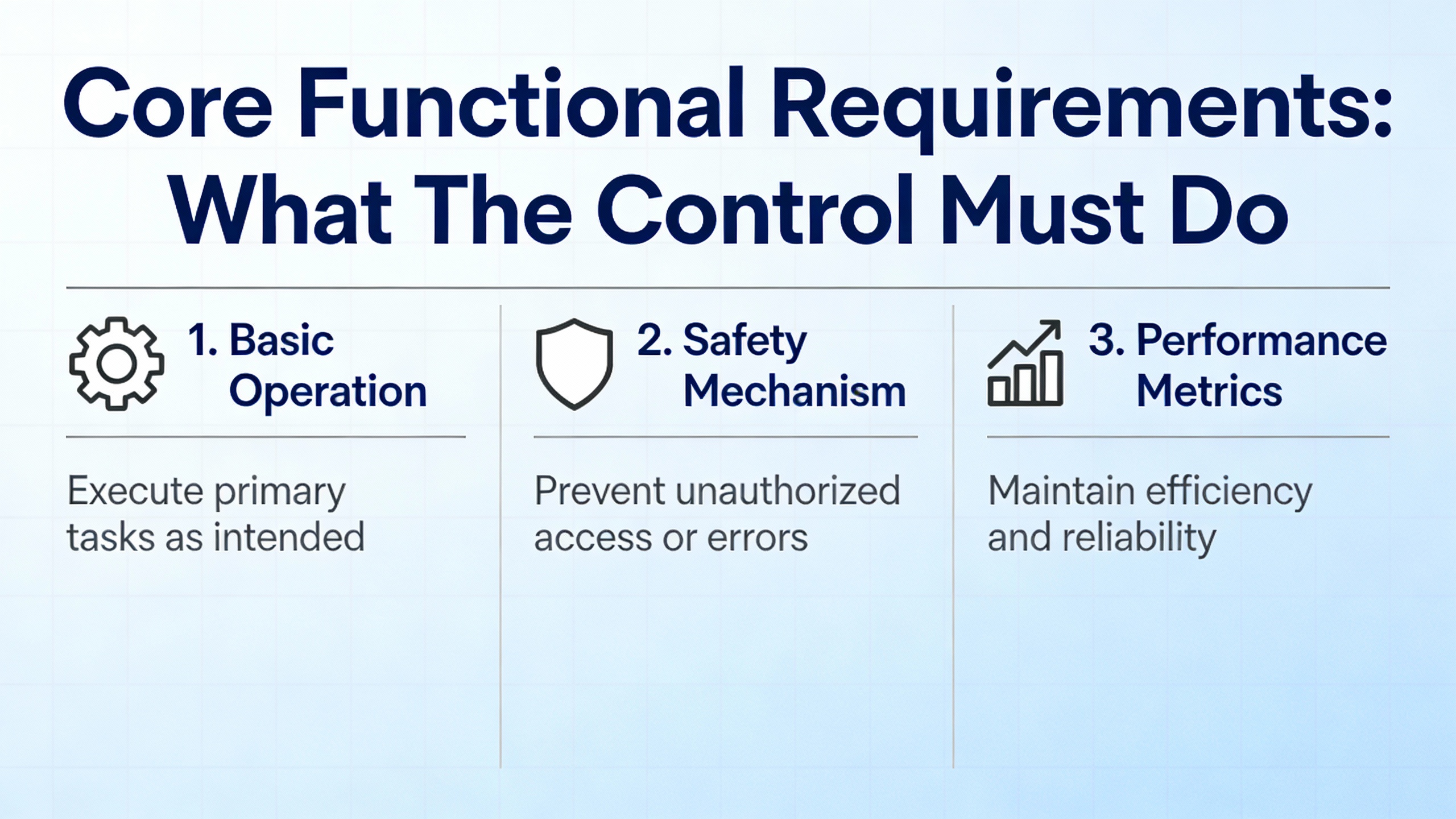
Core Functional Requirements: What The Control Must Do
Safe Startup, Shutdown, and Sequencing
Gas turbine handbooks and industrial case studies agree that automated, thoroughly interlocked sequencing is the first requirement of any control system. A typical control platform governs ignition, acceleration, warm-up, synchronization, loading, and shutdown, enforcing permissives at each step.
Practical examples from Speedtronic-style control logic, described in depth in user discussions of syngas-firing units, show how this works in the real world. Before the turbine is declared ready to start, start-check logic rungs must confirm that numerous conditions are normal: no emergency stop devices are actuated, no fire system fault exists, no turbine-stop signal is present, inlet guide vanes (IGVs) are within their allowable angle band, critical thermocouple readings are consistent, and customer or plant-level permissives have been satisfied.
Generator and grid-related protective functions fit into this logic as well. ANSI device 27 undervoltage relays indicate loss of bus voltage; device 86 lockout relays latch serious protective trips. For example, if two out of three redundant protection modules vote to trip (a two-out-of-three scheme described for VPRO-type hardware), a latched logic signal is set and the system blocks any new start until a human performs a master reset and addresses the underlying fault. This is exactly the behavior you want in a plant feeding critical loads through UPS and power distribution equipment: the turbine cannot quietly re-arm under latent fault conditions.
A sound specification should therefore define, in detail, the required startup and shutdown sequences, the permissive and interlock philosophy, and how faults are latched and reset. It should insist that every start-blocking permissive be associated with a clear process alarm on the HMI, as experienced gas turbine controls engineers recommend, so that operators know precisely why the unit is not ready. It should also require that fire protection and emergency stop circuits be implemented as hardwired, normally closed safety paths that can trip the turbine independent of software, aligning with recommendations in turbine control guidance and power-plant safety standards.
For example, consider a turbine that must dead-bus start a generator feeding a switchboard whose downstream loads include static transfer switches and UPS systems. The control spec should make clear that loss of bus voltage alone does not block a start, but that any active lockout or fire system fault must. That balance is how you enable controlled energization of a dead bus while still preventing dangerous restart conditions.
Fuel, Air, and Load Control For Performance
Once running, the turbine control system is responsible for managing the Brayton cycle in real time: the compressor raises the air pressure, the combustor adds heat at nearly constant pressure, and the turbine expands the hot gas to produce work. The Petrotech discussion of gas turbine efficiency, along with performance-control analyses of GE industrial units, shows how strongly pressure ratio, turbine inlet temperature, and airflow drive overall plant efficiency.
Control algorithms therefore need to manage several tightly coupled loops: fuel flow to meet demanded power or shaft speed, IGV position and compressor bleed to stay within surge margins, and exhaust or firing temperature to protect turbine materials. A turbine performance-control study using exhaust-temperature-based control demonstrates practical strategy: rather than trying to measure and control ignition temperature directly, the system measures exhaust gas temperature and, using known thermodynamic relationships, adjusts fuel to keep the effective firing temperature within limits.
A good specification will state which parameter is the primary control variable for the application. In grid-tied generation, this is often generator megawatts with speed held close to synchronous, while in mechanical drive service it may be shaft speed or torque. It should also define how the system prioritizes between load demand and temperature limits. When ambient temperature increases, for instance, turbine inlet temperature limits become more binding. The control should automatically reduce maximum allowed load to protect hot-section components, even if the operator is calling for more power.
Efficiency considerations must be spelled out as well. The SGT6ŌĆæ2000E example shows that operating at 75 percent load can lower efficiency to around 36.2 percent, and at 50 percent load to about 33.8 percent, compared with roughly 38.5 percent at full load. If your plant typically runs a pair of turbines, it may be more efficient to keep one unit near full load and run the other at a lower output or temporarily offline, rather than operating both at 50ŌĆō60 percent. Control specifications can support such strategies by requiring flexible load-sharing logic across units and by mandating real-time efficiency calculations that operators can see on the HMI.
The controls must also respect compressor and IGV limits. Practical experience reported in field discussions notes that many supposed IGV servo faults are actually due to mis-set mechanical stops or miscalibrated position transducers, with typical minimum operating angles in the low-30-degree range for certain frames. Specifications should require that mechanical stops and position sensors be calibrated to OEM recommendations, not relaxed to mask problems. That type of rigor helps avoid long-term efficiency penalties and surge risks.
Protection and Safety Instrumented Functions
Beyond normal control, the gas turbine control system hosts the protection and safety instrumented functions that keep equipment and people safe. Modern systems, as described in industrial safety-focused articles, integrate with dedicated Safety Instrumented Systems (SIS) designed to IEC 61508 and certified to Safety Integrity Levels such as SIL 2 or SIL 3. These SIS subsystems monitor critical parameters like overspeed, overtemperature, high vibration, low lube-oil pressure, and fire detection, and they execute shutdowns or isolations when risk thresholds are exceeded.
The Gas Turbine Engineering Handbook and leading industrial control suppliers emphasize redundancy and fail-safe design for these paths. Overspeed protection, for instance, is usually implemented with multiple independent speed sensors feeding redundant shutdown logic. Fire protection systems are verified to detect fires, trip the turbine, and release extinguishing agents before the control system will allow a start. Emergency Shutdown (ESD) sequences are engineered to shut fuel and air supplies, apply brakes where used, and activate fire suppression faster than a human could react.
Your specification should therefore separate basic process control from safety instrumented functions, define the required SIL levels for each safety function, and state clearly what the safe state is for each dangerous condition. It should require that safety functions default to shutdown on loss of power, communication, or internal diagnostics, reflecting the ŌĆ£fail-safeŌĆØ guidance in ISA-77 style recommendations for fossil power plants. If your turbine is feeding critical UPS-backed loads in a hospital or data center, those load systems are designed on the assumption that any turbine trip is deliberate. The control system specification is the place where you enforce that assumption.
Hardware and Architecture Specifications
Choosing Between DCS, PLC, or OEM Turbine Controller
From a hardware standpoint, you have several architecture options, each with different implications for lifecycle cost, support, and reliability. A recent industrial overview categorizes them as legacy analog, distributed digital control systems (DCS), programmable logic controllers (PLCs), and OEM turbine-specific controllers. Research on standard digital controls for gas turbines, including ASME conference work on configurable control platforms, reinforces the trend toward reusable, parameterized software running on flexible I/O backplanes.
A concise comparison helps frame the choice.
| Platform type | Typical use case | Strengths | Limitations |
| OEM turbine controller (for example, GE Mark VIe, Siemens T3000, ABB Symphony Plus) | New turbine packages, high-criticality plants | Deep turbine-specific algorithms, fast I/O, built-in redundancy and safety, tight OEM support | Vendor lock-in, higher capital cost, limited flexibility for non-standard logic |
| DCS (for example, large power plant systems) | Multi-unit plants, integrated process plus power | Centralized view, strong analytics, integration with balance-of-plant | May require turbine-specific add-ons; sometimes less specialized for fast rotating machinery |
| PLC-based control | Retrofits, smaller or stand-alone units | Modularity, flexibility, lower cost, easy to expand | More engineering effort to match turbine-specific protection and performance features |
| Legacy analog | Older installations | Simplicity, proven reliability | Weak diagnostics, minimal integration, difficult to maintain or expand |
The ASME paper on standard gas turbine control design advocates an approach where base functionalityŌĆöthe core, validated control and protection logicŌĆöis kept fixed, and unique project requirements are met through configuration and add-on logic, not wholesale program changes. That design reduces the risk of software regression and simplifies testing. When specifying a controller for an industrial plant, particularly for a fleet with multiple turbine types, this kind of configurable standard control can offer more agility than a one-off custom design while still achieving OEM-grade reliability.
Whichever platform you choose, the specification should call for a multi-tier software architecture where low-level sequencing, closed-loop controls, and protection are segregated from operator interfaces and external communications. It should also require that configuration tools allow most changes to be made by parameter adjustment rather than by direct code edits, echoing the best practices highlighted in modern control development literature.
I/O, Sensors, and Data Highway Requirements
Any control system is only as good as its measurements and data transport. The AlliedPG analysis of SGT6ŌĆæ2000E performance, along with classic turbine handbooks, lists the essential instrumentation: thermocouples for exhaust and hot-section temperatures, pressure transducers at compressor and turbine stations, flow meters for air and fuel, and accelerometers or vibration probes on critical bearings and casings. Data acquisition systems convert these sensor signals into high-rate digital streams, enabling both transient analysis and long-term performance trending.
ASME PTC 22, the performance test code for gas turbines, raises the bar further by demanding that test instrumentation and methods meet defined accuracy and uncertainty criteria. It sets out procedures for determining corrected power output, heat rate, exhaust flow, and temperature at standardized reference conditions. While PTC 22 is a testing standard rather than a control specification, it implicitly defines the measurement quality needed if you want credible performance data.
Your control system specification should therefore address, in detail, the number and type of analog and discrete I/O channels; the required measurement ranges, accuracies, and response times; and the need for redundant sensors on safety-critical parameters. It should state that the control systemŌĆÖs data acquisition capability must be adequate to support PTC 22-style performance evaluations, even if formal tests are only occasional.
The communication backbone that carries this dataŌĆöthe control system data highwayŌĆöis also a critical reliability element. A technical overview of gas turbine data highways describes how this network links sensors, controllers, actuators, and monitoring tools, and notes that its integrity directly affects fuel efficiency, emissions, safety, and hardware life. Typical failure indicators include intermittent communication loss, delayed control responses, and erratic sensor trends. Environmental stress, aging cables, and electromagnetic interference are common culprits.
To avoid those pitfalls, the specification should demand robust, shielded wiring and connectors for data paths; error-checked protocols; and, for high-criticality units, redundant communication paths. It should require that the system support detailed communication diagnostics and that historical data logs be easy to export for analysis, as recommended in data-highway troubleshooting guidance.
Power Supply, Redundancy, and Cybersecurity
From a power-systems reliability perspective, the turbine control system belongs in the same category as protection relays and UPS control electronics: it must ride through the disturbances it is responding to. While the research sources focus more on control and protection functions than on power supply details, their repeated emphasis on redundancy and fault tolerance has clear implications.
Modern Mark V and Mark VIe style systems, for example, are described as using ruggedized hardware, redundant processors, and fault-tolerant architectures so that key control functions continue even after individual component failures. Safety- and availability-focused discussions of OEM controllers note redundant CPUs and power supplies, and ŌĆ£plug-and-playŌĆØ I/O modules that can be replaced within minutes.
Your specification should therefore require redundant power supplies for the control system and its critical I/O, fed from independent, conditioned sources. In plants where turbine output feeds UPS-backed switchgear, that often means placing the control power on the same high-reliability battery-backed buses as protection and communication systems. The spec should also call for redundant processors and I/O modules on safety-critical functions, and for voting logic (such as two-out-of-three schemes) for key shutdown signals.
On the cybersecurity side, modern turbine control summaries point out that OEM systems increasingly offer hardened communication architectures certified by the manufacturer. The Gas Turbine Engineering Handbook and digital-twin literature also note cybersecurity and data integration as emerging challenges. It is therefore appropriate to specify role-based access control, segmented control networks, and secure remote-access options for maintenance, aligning your turbine system with the cybersecurity posture of the rest of the plant.
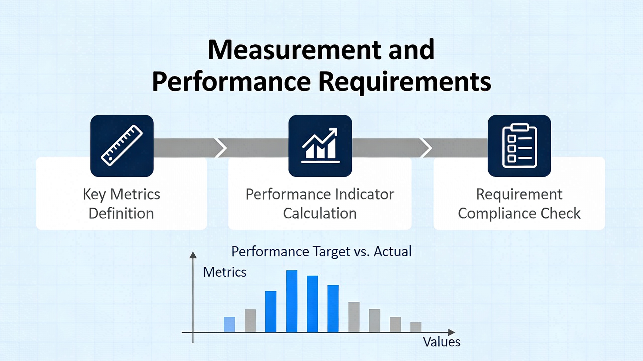
Measurement and Performance Requirements
Aligning With ASME PTC 22 and Related Standards
Specifying the control system solely around control loops and safety functions is not enough if you care about efficiency, fuel cost, and emissions. ASME PTC 22 provides a framework for measuring gas turbine thermal performance at defined test conditions, including how to correct measured results for deviations in ambient temperature, pressure, and humidity. It requires that test planning include an uncertainty analysis to confirm that instrumentation accuracy meets code requirements.
While you may never run a formal PTC 22 test outside commissioning or major overhauls, aligning your control system specification with PTC 22 concepts pays off. If your data acquisition and control system natively capture corrected power, heat rate, exhaust conditions, and fuel flow with sufficient precision, plant personnel can track performance degradation over time without deploying temporary test gear.
For example, if a plant at 2,000 ft elevation and summer conditions wants to compare current performance with its original baseline, the control system should be able to reconstruct what the current output would be under a standardized reference atmosphere. That capability depends on having accurate ambient measurements, reliable shaft power measurements, and consistently calibrated flow and temperature sensorsŌĆöall of which need to be called out in the specification.
Efficiency, Heat Rate, and Condition-Based KPIs
From an efficiency standpoint, the Petrotech overview of gas turbine performance provides useful historical context. The first simple-cycle gas turbines in 1939 operated at about 18 percent thermal efficiency, with turbine inlet temperatures below roughly 1,000┬░F and exhaust temperatures a little over about 500┬░F. Modern large simple-cycle turbines now reach around 40 percent efficiency with inlets near 2,700┬░F and exhausts up to roughly 1,160┬░F. Combined-cycle gas turbine plants have pushed combined efficiencies above 60 percent, with one configuration documented at 63.08 percent.
These gains did not come from thermodynamics alone; they were enabled by better materials, blade cooling, coatings, and, crucially, by tighter control of firing temperatures, compressor cleanliness, and part-load operation. Advanced materials discussed in the Gas Turbine Engineering Handbook enable turbine operating temperatures in the region of about 2,550┬░F, but only if control systems accurately manage cooling flows and avoid temperature excursions.
Industrial analysis of specific units like the SGT6ŌĆæ2000E and broader performance-control case studies build on this with concrete metrics such as thermal efficiency, heat rate, specific fuel consumption, and power-output efficiency. They also note the strong dependence on ambient conditions and load. For instance, performance-control work on gas compression station turbines shows how rising compressor inlet temperatures drive up compressor work, reduce air mass flow, and lower net power output, while higher humidity and lower atmospheric pressure further reduce power and increase specific fuel consumption.
A forward-looking control specification should require that the system calculate and log meaningful key performance indicators: corrected shaft power, fuel flow, heat rate, and at least one normalized performance index. Recent research using graph theory and combinatorics to create a single performance index for gas turbine power plants shows one way to combine subsystem health and performance into a single number, although the specific methodology may vary by plant. The important point is that controls and data acquisition must make such analysis feasible without additional instrumentation.
A simple example illustrates how this helps. Suppose your turbine originally delivered 20 MW at full load with an efficiency of 38.5 percent. Years later, corrected data show that at similar corrected conditions the same load point now yields 18 MW at 35 percent efficiency. The difference may reflect compressor fouling, hot-section wear, or control drift. If the control system has been logging compressor pressure ratio, firing or exhaust temperature, and vibration trends, you can distinguish between aerodynamic, thermal, and mechanical causes and schedule targeted maintenance, rather than guessing.
Digital Twins, Simulation, and Testing
Advanced handbooks and modern industrial articles increasingly highlight digital twins and high-fidelity simulation as central tools for both design and lifecycle support. A digital twin is a virtual replica of the turbine that uses real-time sensor data, historical records, and physics-based models to predict behavior. For turbines like the SGT6ŌĆæ2000E, digital twins support real-time efficiency tracking, what-if analyses, and proactive tuning to improve reliability and performance.
The ASME paper on standard gas turbine controls stresses the value of simulation not just during initial design, but throughout the control systemŌĆÖs life. It recommends using the same modeling framework for initial validation, field commissioning support, and subsequent software changes and upgrades. ISA-77 standards for fossil-fuel plants also include simulator requirements to support operator training and control testing.
When you write your specification, it is worth including explicit requirements for a simulation environment. That may mean requiring a dynamic model of the turbine and its control system, with the ability to inject simulated sensor values and validate logic changes offline before deployment. It may also mean calling for integration hooks for third-party or OEM digital twin platforms so that the plant can implement advanced performance and maintenance analytics as the technology matures.
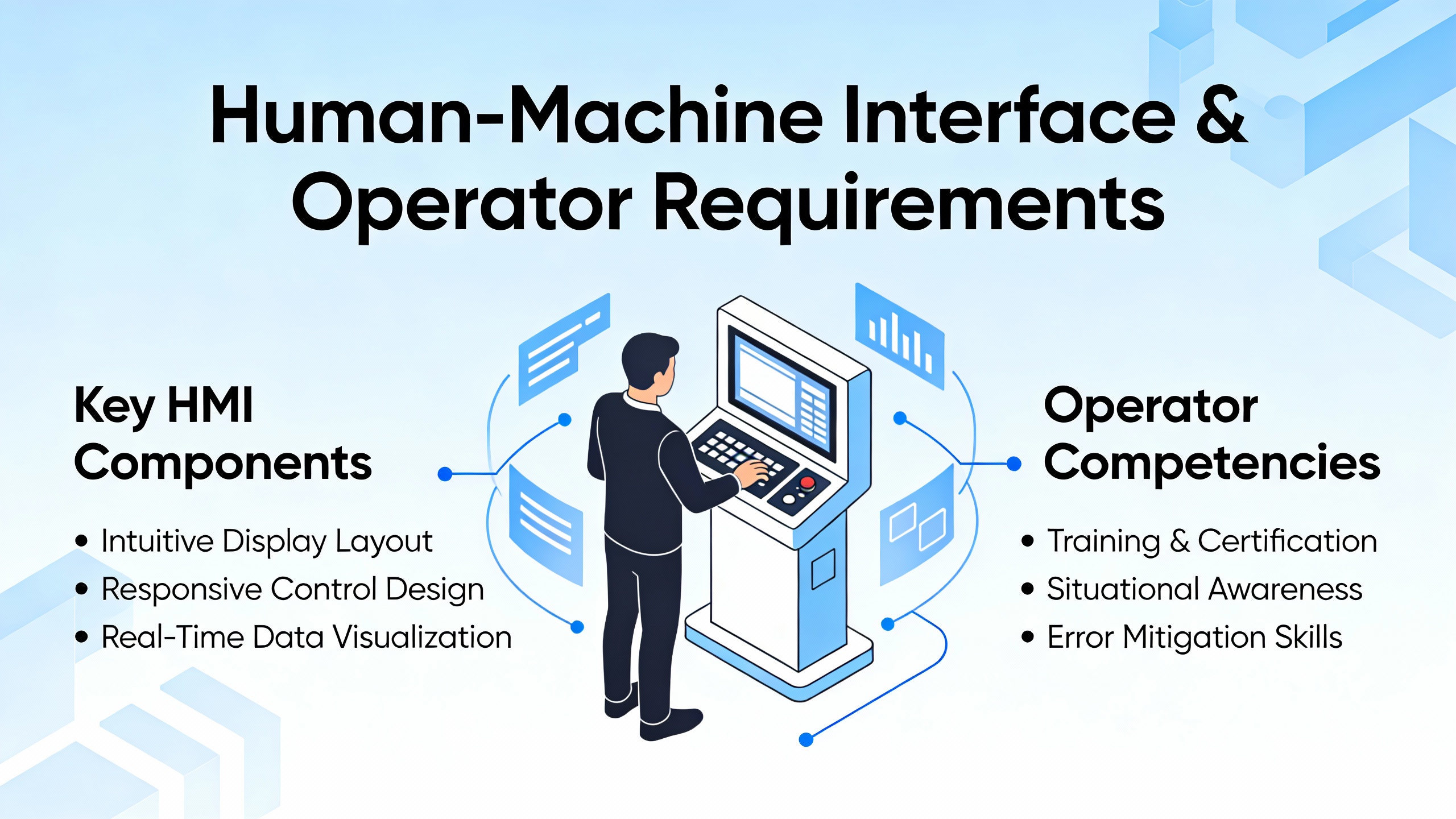
Human-Machine Interface and Operator Requirements
Even the best control logic can be undermined by poor human-machine interfaces. Human-factors studies of gas turbine control consoles describe a microprocessor-based system with a CRT or modern HMI client that simultaneously serves as operator interface, maintenance interface, and configuration environment. To bridge the gap between traditional relay-based controls and digital systems, sequencing logic is often presented as ladder diagrams familiar to plant electricians, not only as abstract Boolean code.
Detailed interface descriptions highlight a consistent screen philosophy. An annunciation area shows a small number of active alarms in chronological order, with the first-out alarm flashing and the ability to scroll through the full list. A command and prompt area supports menu navigation and keyboard commands. Central display pages present bar graphs for speeds, temperatures, and fuel-valve positions; lists of analog values; alarm and shutdown tables; and diagnostic views. Colors, where used, follow clear conventions: normal data in one color, alarms in another, shutdowns in a distinct color, and bar graphs changing color entirely when an alarm or shutdown threshold is crossed.
Maintenance pages expose internal logic states: live ladder diagrams, discrete I/O status with visual indication of active points, configurable constants and setpoints, timer values, self-diagnostics, and forced I/O status. This depth is crucial when diagnosing issues like an unexpected start permissive block or a misbehaving IGV limit.
Discussing start-check logic for syngas-firing turbines, experienced engineers strongly recommend that every single start-check permissive be linked to a process alarm, so when the unit is not ready to start, the operator sees an explicit reason such as ŌĆ£Inlet Guide Vane Fault,ŌĆØ ŌĆ£Fire Protection Not Ready,ŌĆØ or ŌĆ£Bus Undervoltage Lockout Active.ŌĆØ This approach is aligned with ISA-77 HMI guidance for fossil plants, which emphasizes clarity, alarm prioritization, and minimizing cognitive load.
Your specification should therefore define an HMI philosophy rather than leaving it to chance. It should state that critical control functionsŌĆöstart, stop, emergency stop, speed or load raise and lower, horn silence, and local/remote selectionŌĆömust be available on a dedicated hardware panel so the unit can be safely operated even if the main HMI fails, a practice confirmed in interface design literature. It should call for clear alarm management rules, including first-out indication for trips, alarm grouping, and consistent colors or symbols. It should also require views tailored for both operators and technicians, such as high-level overview screens and detailed logic diagnostics.
In a plant feeding mission-critical UPS loads, these interface requirements materially affect reliability. When operators can quickly see why a turbine will not start or why it tripped, they are less likely to force unsafe overrides or repeatedly cycle the machine, both of which can escalate into full plant disturbances.
Future-Proofing: Fuel Flexibility, Decarbonization, and Hybrid Systems
Gas turbine technology is evolving in response to decarbonization policies, emerging fuels, and hybrid power architectures. NETLŌĆÖs Gas Turbine Handbook, along with advanced combustion chapters in technical references, details how gas turbines are being adapted to integrated coal gasification combined cycles, high-hydrogen fuels, and hybrid gas turbineŌĆōfuel cell systems. Combustion chapters describe the challenges of syngas and high-hydrogen combustion, including stability, flame speed, and NOx formation, and survey strategies such as lean premixed combustion, rich-burn/quick-mix/lean-burn combustors, catalytic combustion, and advanced concepts like trapped vortex and low-swirl burners.
Broader energy-system analyses note that natural gas turbines are displacing coal and diesel in many regions and that liquefied natural gas trade is expanding, while at the same time pressure is mounting to reduce greenhouse gas emissions. Gas turbines can support decarbonization by replacing more carbon-intensive plants and, in the longer term, by burning renewable-derived fuels such as hydrogen, synthetic methane, or bio-syngas. Research on hydrogen-enriched gas turbines indicates that suitable combined-cycle configurations can handle high hydrogen fractions, and that hydrogenŌĆÖs wide flammability range and low molecular weight create both opportunities and combustion-control challenges.
These trends have direct implications for control system specifications. If your turbine may eventually fire syngas, high-hydrogen blends, or other non-standard fuels, the specification should call for combustion control hardware and software that can accommodate fuel property variability. That includes more sophisticated fuel metering, flame monitoring, and combustion dynamics control (to handle static and dynamic stability issues) and the I/O to support additional sensors where needed.
Hybrid systems that couple turbines with fuel cells or other advanced cycles, such as the high-temperature steam or advanced Brayton cycles described in NETL material, also place new demands on control. Dynamic simulation of hybrid gas turbineŌĆōfuel cell systems has been identified as an active research area, with control challenges around transient response and shared components. Including a requirement for flexible integration with external hybrid controllers, and for simulation models that can be extended to future configurations, is a pragmatic way to future-proof your control system investment.
Finally, as grids integrate more variable renewables and as electric vehicle adoption reshapes load patterns, gas turbines are increasingly called on to provide fast-ramping, flexible generation rather than flat baseload. That reality should be reflected in specifications for ramp-rate control, minimum load handling, and cycling fatigue management, all of which are touched on in dynamic performance guidance and turbine-governor modeling work, even when full details are behind access controls.
Closing Perspective
When you specify a gas turbine control system for an industrial or commercial power plant, you are not just buying a control panel. You are defining how the prime mover will behave for the next two or three decades: how safely it will start and stop, how efficiently it will burn fuel across seasons, how gracefully it will integrate with your UPS and power protection systems, and how ready it will be for new fuels and new grid demands. Anchoring your specification in proven control architectures, rigorous measurement requirements, solid HMI design, and an explicit path to simulation and future fuels is the most cost-effective reliability upgrade you can make before the turbine ever fires.

References
- https://www.academia.edu/101391996/User_Interface_Description_of_a_Gas_Turbine_Control_System
- https://digitalcommons.uri.edu/cgi/viewcontent.cgi?article=1161&context=mechanical-engineering-capstones
- https://researchrepository.wvu.edu/cgi/viewcontent.cgi?article=2771&context=etd
- https://netl.doe.gov/carbon-management/turbines/handbook
- https://oaktrust.library.tamu.edu/bitstreams/26565ae0-32d2-47f7-8e4f-33375dba97e1/download
- https://web.mit.edu/smadnick/www/wp/2018-12.pdf
- https://www.nap.edu/read/25630/chapter/3
- https://ntrs.nasa.gov/api/citations/20170000884/downloads/20170000884.pdf
- https://wp.nyu.edu/mind/2023/08/03/an-introduction-to-gas-turbine-technology-and-gas-turbine-control-systems/
- https://etd.ohiolink.edu/acprod/odb_etd/ws/send_file/send?accession=dayton1552556049435026&disposition=inline


 Videos
 News
News Applications


Leave Your Comment