Gas turbines sit at the heart of many industrial and commercial power systems, from combinedŌĆæcycle plants feeding large grids to industrial drives supplying critical processes. Yet, when I walk into a plant that struggles with reliability, the root cause is often not the turbine hardware itself but an incomplete or poorly specified control system. A robust, detailed control datasheet is one of the most powerful tools you have to avoid that outcome.
In this article, I will treat the gas turbine control datasheet the way we treat a UPS or static transfer switch specification in critical power: as a contractual definition of performance, protection, and integration. Drawing on operational experience and published work from OEMs, integrators, and peerŌĆæreviewed studies, we will look at how to structure that datasheet, which parameters truly matter, and how to configure a control system that delivers reliable, predictable power for decades.
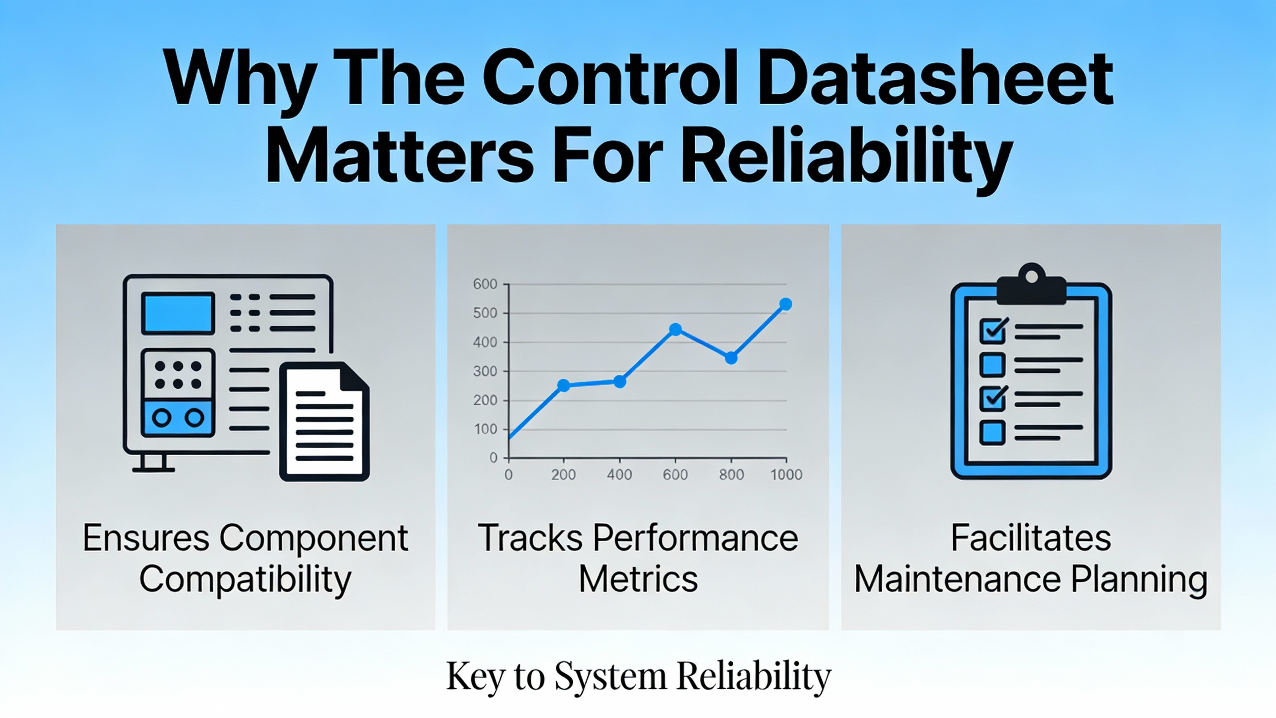
Why The Control Datasheet Matters For Reliability
Modern gas turbine control systems are integrated platforms of sensors, controllers, and actuators that regulate fuel flow, air flow, and auxiliaries to keep speed, load, temperature, and vibration within safe limits. Industry summaries from gasŌĆæturbine specialists describe typical architectures with thermocouples, pressure transmitters, speed pickups, and vibration probes feeding redundant I/O and controllers, often with twoŌĆæoutŌĆæofŌĆæthree voting logic and independent hardwired protection circuits for safe shutdown.
This is not just theory. A case described by Power Engineering magazine showed a plant running three gas turbines on a control system roughly fifty years old. After a modern control upgrade, starting reliability improved from about 50 percent to greater than 90 percent, with no failed starts attributed to the new controls. In peaking service, where a turbine may need to start within about fifteen minutes and run for thirty minutes, that difference in starting reliability translates directly into revenue and contractual performance.
Maintenance studies from component manufacturers reinforce how strongly control quality and maintenance interact. St. Marys Carbon notes that gas turbine efficiency commonly ranges from about 20 to 40 percent in simpleŌĆæcycle service, and that fouling, poor combustion control, and bearing issues are recurring causes of lost efficiency and forced outages. When the control system cannot see accurate temperature, pressure, or vibration data, or cannot sequence starts consistently, these physical problems appear as nuisance trips, slow starts, and chronic underŌĆæperformance.
Given this backdrop, the datasheet for your turbine control system is not a formality. It defines the control architecture, parameter coverage, redundancy, diagnostics, and cybersecurity posture that will either support or undermine your plant’s availability and profitability for the next twenty or thirty years.
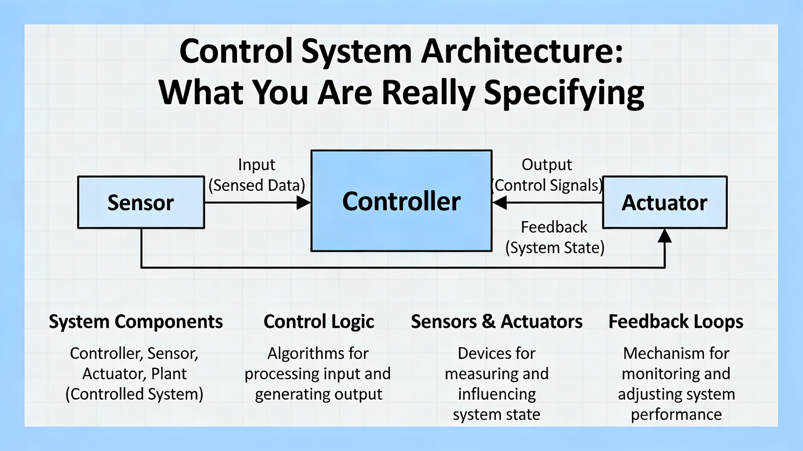
Control System Architecture: What You Are Really Specifying
Before you can list parameters, your datasheet must lock in the architectural choices that determine how the turbine will be monitored and governed. Across OEMs and integrators, three main families of solutions appear repeatedly in the literature.
Core Architecture Options
Gas turbine control platforms fall broadly into three categories described by firms such as Unisys Group, Emerson, and academic overviews of GE Mark V/VIe systems.
| Architecture type |
Typical usage |
Key strengths |
Typical limitations |
| OEMŌĆæspecific controller (e.g., GE Mark V/VIe, Siemens T3000, ABB Symphony Plus) |
New utilityŌĆæscale units, many existing fleets |
Deep turbineŌĆæspecific logic, proven sequencing, tight integration with OEM diagnostics |
Proprietary, often “black box” to owner; upgrades and changes tightly coupled to OEM |
| PLCŌĆæbased control (Siemens S7, AllenŌĆæBradley, Schneider, etc.) |
Smaller turbines, industrial drives, retrofits |
Modular, flexible, costŌĆæeffective, familiar to many plant teams |
Requires careful engineering for highŌĆæintegrity protection, may lack turbineŌĆæspecific features by default |
| Open DCS / plantŌĆæwide platform (e.g., Emerson Ovation, thirdŌĆæparty DCS) |
StationŌĆæwide integration, multiŌĆæunit plants, major retrofits |
Unified architecture for turbine, balanceŌĆæofŌĆæplant, and protection; strong trending, historian, cybersecurity |
More complex upfront design; requires disciplined change management and skilled integrator |
Unisys highlights that OEM platforms like GE Mark VIe or Siemens T3000 are tailored to turbine characteristics and often include advanced startup/load logic, diagnostics, and safety functions. A New York University overview of GE Mark V notes its robust, redundant design, harshŌĆæenvironment tolerance, and tight integration with SCADA and plant DCS.
On the other side, Power Engineering reports that many turbines installed between roughly 1990 and 2005 are now reaching their first or second control upgrade window, and owners are actively moving away from OEM “black box” controls toward open, thirdŌĆæparty control systems. These open systems give plant staff transparent access to live logic and process data, enabling them to become selfŌĆæmaintainers rather than captive customers.
From a reliability advisor’s perspective, the datasheet should state clearly whether you are procuring an OEMŌĆæspecific controller, a PLCŌĆæcentric solution, or a full DCS implementation. It should then spell out how that system will integrate with the rest of the plant—generators, protection relays, UPS systems, and SCADA—rather than leaving integration to afterŌĆætheŌĆæfact engineering.
Protection And Safety Layers
Gas turbine control is never just about setpoints; it is also about layers of protection. Modern systems described by gasŌĆæturbine OEM summaries and by Unisys use dense realŌĆætime monitoring and alerting. Sensors track combustion temperature, exhaust gas composition, bearing vibration, rotor speed, and lubeŌĆæoil pressure against defined limits. Automated emergency shutdown sequences act on overspeed, fire, flame loss, and other hazards by cutting fuel and air, applying brakes where relevant, and triggering fire systems.
A key theme in safety standards is functional independence. Dedicated Safety Instrumented Systems, designed to safety integrity levels such as SIL 2 or 3, often run separately from the main control system, as noted in Unisys’ discussion of turbine SIS architectures. These SIS platforms execute critical actions such as shutdown, isolation, and restart checks even if the main controller or HMI fails.
Older plants illustrate why this layered design matters. Power Engineering describes a case where an HMI client in the main control room failed on a proprietary OEM control system. Operators were forced to work at an HMI located physically next to 480 V distribution breakers and a 13.8 kV generator breaker, inside a highŌĆæhazard arcŌĆæflash zone. Because the system was closed and hardware was customized, repair required sending equipment back to the OEM, leaving the plant with degraded redundancy for weeks.
To avoid similar exposure, your datasheet should define, in engineering language, which trips are executed in the SIS, which remain in the basic process control system, what voting logic is used at each layer, and how the shutdown matrix is implemented and tested. Industry practice, as summarized by gas turbine control references, is to use twoŌĆæoutŌĆæofŌĆæthree voting on the most critical measurements, with separate hardwired protection wherever a software fault must not be able to suppress a trip.
Networking, HMI, And Data Infrastructure
Digitalization has changed the expectations for gas turbine control. Modern references from OEMs and integrators consistently describe control systems integrated into an HMI or SCADA layer that provides realŌĆætime trends, alarms, event logs, and sequenceŌĆæofŌĆæevents recording at millisecond resolution.
Unisys and NYU’s Mark V overview both emphasize userŌĆæfriendly HMIs that present realŌĆætime data and alarms in ways operators can act on quickly. Emerson’s material on its Ovation gas turbine controls stresses turnkey installations that improve operator performance and streamline maintenance by giving a clear view of turbine status. Articles in Power magazine further describe the role of informationŌĆæenabled DCS platforms and historians in reducing nuisance trips and cutting startup times by about twentyŌĆæfive percent at a cogeneration plant after a control upgrade.
In parallel, research published on ScienceDirect demonstrates how advanced analytics, including deep learning models, can use highŌĆædimensional operational data to identify working conditions and predict gas turbine performance across multiple operating modes. Another study applies graphŌĆætheory methods to gas turbine power plants, generating a single performance index from many subsystems such as air filtration, compressor, turbine, fuel, oil system, and alternator. Both threads assume rich, highŌĆæquality data coming from the control system.
Your datasheet should therefore specify data infrastructure as rigorously as it does I/O counts. That includes historian requirements, minimum time resolution for logs and sequenceŌĆæofŌĆæevents, key tags to be archived, and how data will be exposed to enterprise systems or fleet monitoring platforms. Skimping here limits your ability to adopt predictive maintenance, advanced emissions control, or fleetŌĆæwide optimization later.
A simple way to capture expectations is to treat data as a firstŌĆæclass parameter group, not an afterthought, as in the following conceptual table.
| Data feature |
Datasheet focus |
Supporting evidence |
| RealŌĆætime trends and SOE recording |
Define minimum time resolution and time synchronization (for example, millisecondŌĆælevel for trip analysis) |
OEM and integrator materials describe millisecondŌĆæresolution trends as standard for rootŌĆæcause analysis of trips and nearŌĆæmisses |
| LongŌĆæterm historian |
Identify retention period, key tags, and required integrations with plant historian or enterprise systems |
Power magazine case shows large reductions in nuisance fails and startup times after deploying an informationŌĆæenabled DCS and historian |
| Data quality and validation |
Specify calibration intervals and diagnostics for critical instruments |
Turbine instrumentation analyses stress that bad or delayed measurements undermine control logic and can cause unstable combustion or missed alarms |
| Analytics and export |
Clarify whether data must support future AI or advanced analytics and how export will be handled |
DeepŌĆælearning and graphŌĆætheory studies assume highŌĆævolume, highŌĆæquality operational data for reliable performance modeling |
Critical Parameter Groups Your Datasheet Must Capture
Once the architecture is clear, the core of the datasheet is the parameter set. Modern gas turbine control systems, as described by sources from Unisys, NYU, and turbine control summaries, typically manage startup sequencing, speed and load control, inlet and exhaust temperature control, combustion staging, compressor surge protection, and coordinated shutdown. The challenge is to translate that into a practical, auditable parameter list.
Speed, Load, And Grid Support
At a minimum, the control system must regulate turbine speed and generator load to match demand while supporting grid frequency and voltage. Unisys highlights that modern turbine controllers continuously adjust fuel flow and output to follow demand, maintain grid stability, avoid surge or overheating, and coordinate with combinedŌĆæcycle or hybridŌĆærenewable plants during synchronization and transitions.
From a datasheet perspective, that means explicitly defining operating modes, such as baseŌĆæload, peakŌĆæload, and automatic generation control participation, along with the associated ranges of load, ramp rates, and allowable overshoot. While the cited materials do not list specific ramp numbers, they do demonstrate how critical startup and loading behavior is to commercial performance. Power Engineering describes peaking units expected to start and synchronize in about fifteen minutes and then run for roughly half an hour, with liquidated damages if they fail to meet demand.
In practice, I advise owners to ensure the datasheet names the acceptable startup times, automatic and manual loading modes, and how the turbine will respond to grid frequency deviations or voltage disturbances. These are powerŌĆæsystem questions as much as turbine questions.
Temperature And Combustion Limits
Temperature control is central to both performance and hardware life. A technical discussion of GE Frame machines notes that raising firing temperature increases capacity but is limited by metal temperature constraints and sharply rising nitrogen oxide formation above about 2,800°F. Petrotech’s overview similarly observes that turbine inlet temperatures for modern machines exceed roughly 2,300°F, with compressor discharge air used for blade cooling at a modest efficiency penalty.
Academic work on gas turbine thermodynamics, using five years of operational data for a 31.5 MW unit, shows that the combustion chamber is the largest source of irreversibility when examined with exergy methods. Increasing turbine inlet temperature and appropriate compressor pressure ratios both improved overall exergy efficiency, but higher ambient temperatures degraded it.
On the exhaust side, a synergetic control study on a heavyŌĆæduty gas turbine underlines the need to regulate both generated power and exhaust gas temperature through coordinated fuel and airŌĆæflow control. Excessive exhaust gas temperature can drive thermal stress and accelerate creep or cracking in hotŌĆæsection components.
The datasheet should therefore define: which temperature measurements are considered primary for protection; how many independent sensing points (for example, multiple thermocouples per sector); the averaging or voting logic; and the key limits for startup, normal load, and fastŌĆæstart modes. It should also specify how the controller will react to temperature spreads or failed sensors, which are common precursors to damage and trips.
A practical example makes this concrete. Suppose your turbine is designed for a nominal firing temperature that translates into about 2,700°F under baseŌĆæload natural gas firing. If ambient air heats up by roughly 18°F during the afternoon, research indicates that overall exergy efficiency may drop by about two percent, and literature surveys suggest that power output can decrease by twenty to thirty percent when ambient temperature moves from around 77°F to the 95–113°F range. Your datasheet should clarify whether the controller will automatically adjust load limits based on ambient temperature and inlet conditions to keep firing and exhaust temperatures within safe envelopes.
Fuel, Emissions, And Environmental Control
Real power plants often run multiple fuels, and the control datasheet must reflect their very different behavior. A detailed forumŌĆæbased analysis of GE Frame turbines highlights that for a Frame 7FA unit, rated output at standard conditions was about 171.7 MW on fuel gas and 183.8 MW on fuel oil. At a representative ambient condition of about 57°F, a unit produced around 174 MW on gas and roughly 191 MW on oil. Operators had to preŌĆæselect a lower load on oil, about 170 MW, to avoid encroaching on mechanical or emissions limits.
The same analysis emphasizes that while oil firing can yield higher shaft power on certain frames, it consistently delivers worse heat rate, meaning poorer fuel efficiency, than gas firing. It also explains how water injection for nitrogenŌĆæoxide control on fuel oil increases mass flow and power but must be coordinated carefully.
Other sources describe modern Dry Low NOx combustion systems, which continuously adjust fuel staging and mixing to minimize NOx and carbon monoxide. WellŌĆætuned DLN systems can cut NOx emissions by about forty to sixty percent compared with older diffusionŌĆæflame designs, depending on fuel quality and operating mode. When DLN is not sufficient, selective catalytic reduction downstream is used as an external NOx control method.
The datasheet should spell out supported fuels, the control modes for switching between them, any associated water or steam injection schemes, the type of combustion system (for example, DLN), and how emissions are measured and controlled. It is vital to document which emission limits apply under which combinations of fuel, ambient condition, and load level. Without this, operators are left managing a complex fuel/emission/power tradeoff by trial and error.
Mechanical Health, Vibration, And Lube Systems
Reliability is not just about combustion; it is rooted in bearings, seals, and rotating parts. Unisys notes that modern control systems use vibration and lubeŌĆæoil monitoring to detect misalignment, bearing wear, and other issues early. St. Marys Carbon identifies compressor blade fouling, combustion problems, bearing failures, and thermal stress in turbine blades as common causes of efficiency loss and unplanned outages.
A dedicated analysis of gas turbine controls and instrumentation problems underscores that bad readings, failed automatic actions, or communication errors can lead directly to performance loss and safety risk. Early warning signs include erratic measurements, sluggish controls, nuisance alarms, and unexplained performance degradation despite steady fuel and air conditions. Root causes may be sensor aging, harsh environment, electromagnetic interference, or software misconfiguration, and are best addressed through structured rootŌĆæcause analysis rather than ad hoc device replacement.
In your datasheet, vibration, lube oil, and other mechanical health parameters deserve equal status with combustion parameters. Define the vibration monitoring hardware and thresholds, lubeŌĆæoil pressure and temperature limits, and the alarm and trip hierarchy that protects bearings and shafts. Also define how the control system will detect sensor failures and how many failed channels can be tolerated before a safe shutdown is required.
Ambient Conditions, Humidity, And Performance Monitoring
Ambient air conditions are a major performance driver. St. Marys Carbon lists intake air temperature as a key factor: warmer air has lower density, reducing mass flow, power output, and efficiency. The exergy study cited earlier quantified this effect, showing that a fiveŌĆædegree Kelvin increase in ambient temperature, about nine degrees Fahrenheit, reduced overall exergetic efficiency by around one percent in the studied plant.
Humidity matters as well. An application note from Vaisala explains that turbine efficiency and power increase when intake air is cooler and denser, and that inletŌĆæair cooling is widely used in warm climates. They note that a oneŌĆædegree Celsius reduction in intake air temperature, about 1.8°F, can increase turbine power output by up to 0.5 percent. Over a fiveŌĆædegree Celsius, roughly nineŌĆædegree Fahrenheit drop, that can translate into about a two to twoŌĆæandŌĆæaŌĆæhalf percent power gain. Fogging systems that evaporate fine water droplets into the inlet stream are one common approach; they also tend to increase humidity, which can reduce NOx formation.
However, fogging and high humidity bring risks of condensation or icing, especially near freezing conditions. To avoid damage from water droplets or ice in the compressor and turbine, operators must keep dew point below both air temperature and inlet surface temperatures, with safety margins to account for sensor uncertainty. HighŌĆæaccuracy dewŌĆæpoint measurements allow controls to run fogging or antiŌĆæicing systems closer to these limits without harming equipment.
A control datasheet that ignores ambient sensors and intake conditioning is incomplete. You should define which ambient and inlet parameters are measured, the required accuracy of temperature and humidity instruments, and the control strategies for inlet fogging or chilling systems. You should also specify how the turbine control will coordinate with those systems, especially where power augmentation or emissions compliance depends on them.
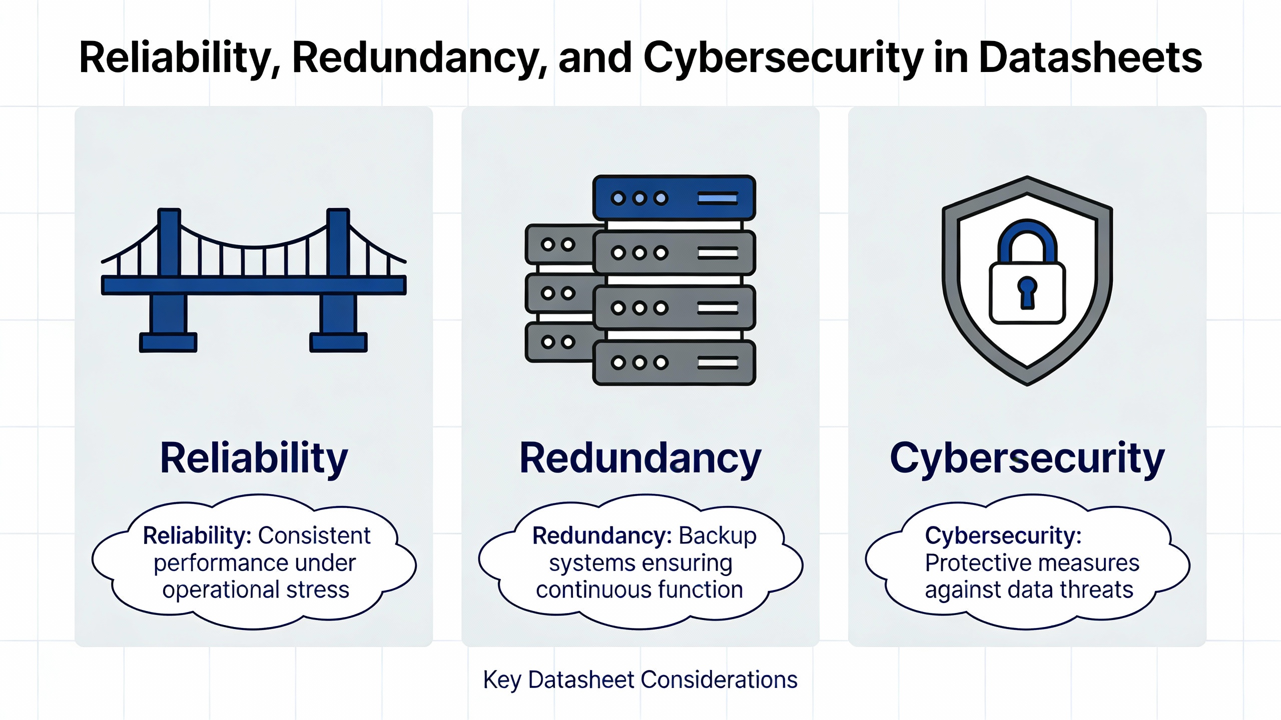
Reliability, Redundancy, And Cybersecurity In The Datasheet
From a powerŌĆæsystem reliability viewpoint, the configuration choices that most affect longŌĆæterm plant performance are redundancy, diagnostics, and cybersecurity. These are often underŌĆæspecified, leading to surprises during commissioning or after the first serious disturbance.
Redundant Architectures And Voting Logic
As already noted, many modern gas turbine controls use redundant processors, power supplies, communication buses, and I/O, supported by voting logic. Unisys describes redundant and faultŌĆætolerant architectures where duplicated processors and communication paths ensure continuous operation, and where software can isolate a faulty module while the rest of the system continues to run. Gas turbine control overviews similarly reference twoŌĆæoutŌĆæofŌĆæthree voting on critical measurements and separate hardwired protection circuits.
The performance benefits of wellŌĆæimplemented redundancy are clear. Articles in Power magazine show that properly engineered control upgrades can eliminate nuisance fails and materially improve starting reliability in multiŌĆæunit plants. Conversely, Power Engineering’s critique of OEM “black box” systems shows how proprietary, custom hardware and nonŌĆæstandard HMIs can erode redundancy and increase downtime when failures occur, because repair often requires sending hardware back to the OEM.
The datasheet should therefore define redundancy requirements explicitly: how many controller modules, how many power supplies, which I/O modules are redundant, and how voting is implemented for each protected measurement. It should also clarify what happens on loss of one controller or one communication link, particularly for gridŌĆæcritical functions like frequency and voltage support.
Diagnostics, Analytics, And Predictive Maintenance
Reliable operation requires not only redundancy but also strong diagnostics and predictive capabilities. Unisys emphasizes continuous trend monitoring of temperatures, vibration, and fuel consumption, often augmented by analytics to predict failures and reduce unplanned outages. OEM and integrator materials on modern digital controls note the role of advanced diagnostics, alarm management, and event logging in troubleshooting trips and near misses.
Academic work further illustrates what is possible when control systems deliver rich data. A deepŌĆælearning based framework for gas turbine performance prediction combines knowledgeŌĆæguided feature selection, multiŌĆæcondition identification, and dynamic modeling to predict behavior under shifting loads and ambient conditions. GraphŌĆætheoryŌĆæbased performance indices constructed from multiple subsystems provide a single numerical measure for real versus ideal performance. Both approaches are only feasible when the control system routinely collects accurate, highŌĆæresolution data on many parameters.
From an O&M standpoint, St. Marys Carbon recommends adhering to scheduled maintenance intervals, monitoring compressor health and air intake conditions, maintaining clean turbine blades, and ensuring proper lubrication and fuel quality. Turbine instrumentation analyses recommend regular calibration and loop tuning, functional testing of trips, and training operators to recognize early warning signs. These tasks are much easier when the controller’s diagnostics and trending are well designed.
In your datasheet, treat diagnostics as a specification item, not a marketing feature. Define which parameters must have builtŌĆæin selfŌĆætests, what alarms are required for degraded but not failed states, and what sort of trend and report generation is expected. Make sure the control platform supports exporting data for external analytics, because predictive maintenance tools are evolving quickly.
Cybersecurity And Compliance
As more control systems connect to plant networks and remote monitoring centers, the attack surface expands. Power magazine notes that modern controls and IoT integration increase exposure to physical and digital threats, and references NERC Critical Infrastructure Protection standards as a benchmark for securing critical power infrastructure. ThirdŌĆæparty control system providers discussed by Power Engineering often incorporate services to help owners meet such requirements.
Gas turbine control overviews from OEMs and integrators recommend segregated control networks, roleŌĆæbased access control, secure remoteŌĆæaccess gateways, regular patch management, backup and validation of control logic, and disciplined change management. Open, standardsŌĆæbased networks like those described in converged plantwide Ethernet reference architectures are often used to implement segmented, manageable control networks that support expansion while maintaining security.
Your datasheet should capture cybersecurity expectations as clearly as you define trip limits. That includes network zoning between control, supervisory, and business networks; authentication and authorization requirements for users; secure remoteŌĆæaccess provisions, if any; and expectations for patching and antivirus management. It should also define logging and audit requirements, especially if you operate in a regulated environment with compliance obligations.
Practical Example: A Multimode Turbine Control Datasheet In Action
To see how these architectural and parameter decisions intersect, consider a simplified example informed by the GE Frame 7FA performance discussion and by field examples of modernizations.
Imagine a midŌĆæmerit combinedŌĆæcycle plant with a heavyŌĆæduty gas turbine that can burn either natural gas or fuel oil. At standard conditions, the machine produces about 170 MW on gas and around 180 MW on oil. At a slightly cooler condition of roughly 57°F, operators observe about 174 MW on gas and 191 MW on oil, consistent with observations in the technical discussion. However, fuel oil operation carries tighter emissions constraints and worse heat rate.
The original OEM control, delivered in the late 1990s, is a proprietary platform with limited diagnostics. As the plant moves toward more frequent cycling, the owner decides to migrate to an open DCSŌĆæbased control system that will also manage the heatŌĆærecovery steam generator and balanceŌĆæofŌĆæplant.
In the control datasheet, the owner specifies: an open DCS architecture with redundant controllers and I/O; a dedicated SIS rated to SIL 2 or 3 for overspeed, flame loss, and critical pressure/temperature trips; twoŌĆæoutŌĆæofŌĆæthree voting on exhaustŌĆægas temperature and key pressure transmitters; and integrated HMI and historian with millisecond resolution sequenceŌĆæofŌĆæevents recording. Ambient and inlet measurements are specified with clear accuracy requirements, enabling future fogging or inlet chilling projects.
On the parameter side, the datasheet defines distinct operating envelopes for gas and oil firing, including maximum load, firing temperature limits, and expected heat rate behavior. It defines water injection limits for oil operation, tied to NOx control, and links them to exhaustŌĆætemperature and emissions monitoring. Startup and loading sequences are specified for both fuels, with the requirement that each mode achieve safe synchronization within defined time and thermalŌĆæstress limits.
Finally, the datasheet captures cybersecurity and diagnostics expectations, including roleŌĆæbased access, a formal changeŌĆæmanagement workflow, and data export to the owner’s fleet monitoring center.
When such a datasheet is enforced during design and factory acceptance testing, the result is a control system that can safely deliver the higher power available on oil when needed, without breaching emissions or thermal constraints, and can return to gas while maintaining efficient, predictable operation. It also positions the plant for future analytics and conditionŌĆæbased maintenance, rather than locking it into a blackŌĆæbox platform.
Preparing Your Team For A DatasheetŌĆæDriven Upgrade
Even the best datasheet is only as effective as the organization that uses it. Experience and industry guidance both point to several practices that make control upgrades and new projects less risky.
Emerson notes that controls and automation represent a small fraction of total plant capital cost, yet they have outsized leverage on reliability and compliance. Power magazine emphasizes that modernizing controls is not just swapping hardware; it is rethinking how the entire station will operate for the next two or three decades. ThirdŌĆæparty control providers described by Power Engineering stress collaboration, plantŌĆæspecific customization, and lifecycleŌĆæbased migration paths instead of wholesale “rip and replace” approaches.
On the maintenance side, St. Marys Carbon and turbine instrumentation analyses recommend disciplined sensor calibration, functional testing of protection trips, validation of interlocks after any change, and thorough operator training for abnormal events. Unisys and other modern control references show that enhanced HMIs, alarm management, and diagnostics tools are only effective when operators are trained and procedures are updated to match.
When you adopt or update a control datasheet, treat it as a living document. Revisit it after major outages and upgrades, incorporating lessons learned about alarms, trips, or parameter gaps. Align it with your plant’s reliability program and asset management tools, so that control parameters and event data feed directly into rootŌĆæcause analyses and improvement plans.

Brief FAQ
How detailed should a gas turbine control datasheet be?
A useful rule of thumb is that a control datasheet should contain enough detail for an experienced integrator to design, implement, and test the system without having to guess your operating philosophy. Industry examples show that underŌĆæspecified controls often lead to proprietary choices, default settings, or unverified assumptions that hurt reliability later. By contrast, plants that define architecture, parameter limits, redundancies, data requirements, and cybersecurity upfront are far more likely to achieve the high availability figures, often above 98 percent, reported for wellŌĆæmaintained combinedŌĆæcycle plants.
Is it worth replacing a functioning but old OEM control system?
Evidence from case studies described in Power Engineering and Power magazine suggests that replacing aging or obsolete controls can yield substantial gains in starting reliability and nuisanceŌĆætrip reduction, even when the turbine hardware is unchanged. For units installed in the 1990s or early 2000s, many owners now face their first or second controls upgrade decision. Given that modern controls can improve diagnostics, ease emissions compliance, and reduce dependence on proprietary hardware, a carefully specified upgrade guided by a strong datasheet often pays for itself through reduced downtime and more aggressive, profitable dispatch.
Closing
As a powerŌĆæsystem specialist, I view the gas turbine control datasheet as one of the most important reliability instruments you can own. When it clearly defines architecture, parameters, redundancy, diagnostics, and cybersecurity, it turns the control system from a opaque black box into a transparent, manageable asset that supports safe, flexible, and profitable operation. Invest the time to build that datasheet well, and it will repay you every day your turbines start, synchronize, and carry load exactly as expected.
References
- https://www.academia.edu/91522038/Assessment_of_effect_of_operation_parameters_on_gas_turbine_power_plant_performance_using_first_and_second_laws
- https://huskiecommons.lib.niu.edu/cgi/viewcontent.cgi?article=2638&context=allgraduate-thesesdissertations
- https://scholarcommons.sc.edu/cgi/viewcontent.cgi?referer=&httpsredir=1&article=3255&context=etd
- https://digitalcommons.uri.edu/cgi/viewcontent.cgi?article=1161&context=mechanical-engineering-capstones
- https://oaktrust.library.tamu.edu/bitstreams/26565ae0-32d2-47f7-8e4f-33375dba97e1/download
- https://upcommons.upc.edu/bitstreams/89a89c8e-b671-453a-b658-332c007a5fe6/download
- https://netl.doe.gov/sites/default/files/gas-turbine-handbook/1-1.pdf
- https://dspace.mit.edu/bitstream/handle/1721.1/46564/42242089-MIT.pdf?sequence=2
- https://ntrs.nasa.gov/api/citations/20100036217/downloads/20100036217.pdf
- https://wp.nyu.edu/mind/2023/08/03/an-introduction-to-gas-turbine-technology-and-gas-turbine-control-systems/


 Videos
 News
News Applications


Leave Your Comment