Why Ethernet Connectivity Matters So Much In Power Systems
In critical power environments, your Ethernet link to an AllenŌĆæBradley controller is part of the protection system, not just an IT convenience. IndustrialAutomationCo points out that network failures in automation quickly translate into downtime, production inefficiencies, and even critical system breakdowns. When that controller is coordinating UPS systems, transfer switches, battery rooms, or inverters, a ŌĆ£simpleŌĆØ Ethernet issue can silently remove your visibility into protection and control.
In my work commissioning and troubleshooting UPSŌĆæbacked control systems, most ŌĆ£PLC problemsŌĆØ that land on my desk turn out to be Ethernet path problems: a misŌĆæbound driver, a bad switch port, an IP conflict, or an overŌĆæstressed network card. The good news is that most of these issues can be resolved with a methodical approach and the right use of Rockwell and network diagnostics.
This guide walks through fieldŌĆætested troubleshooting steps that draw on Rockwell Automation guidance, RealPars training material, Electric NeutronŌĆÖs troubleshooting notes for AllenŌĆæBradley PLCs, Inductive Automation forum experience, and practical Ethernet troubleshooting practices from RTA Automation and others. The focus is on EtherNet/IP connections to CompactLogix, ControlLogix, MicroLogix, and related devices, but the same discipline applies broadly across your OT network.
Understand What ŌĆ£No Ethernet ConnectionŌĆØ Really Means
When a technician says, ŌĆ£I canŌĆÖt connect to the AllenŌĆæBradley PLC,ŌĆØ they might be seeing any of several different symptoms. RealPars describes cases where the PLC does not appear at all in the EtherNet/IP browse list, or where attempts to go online simply time out. Rockwell AutomationŌĆÖs RSLinx Classic documentation describes a red X over an Ethernet driver icon when the driver is faulted or cannot communicate. Electric NeutronŌĆÖs troubleshooting guide mentions ŌĆ£node not respondingŌĆØ alarms from remote I/O or HMIs when there are IP conflicts, subnet mismatches, or bad switches.
Causes behind these symptoms typically fall into a few buckets. The first is basic physical or power issues: dead switches, disconnected patch leads, or failed ports. The second is IP addressing and configuration: wrong subnet, gateway, or IP conflict. The third is driver and protocol mismatch: for example, trying to talk to a MicroLogix controller with a ControlLogixŌĆæoriented driver, as one Inductive Automation forum thread documents. The fourth is resource exhaustion or deviceŌĆæside limits, such as PLCŌĆæ5 Ethernet modules running out of available connections as described in a case on the MrPLC community.
The key to fixing the problem quickly is to treat it as a system issue, not just a software popŌĆæup. That starts with defining scope.
Step 1: Define The Scope Of The Outage
Before changing anything, determine how wide the impact is. Northwest Career CollegeŌĆÖs guidance for IT technicians applies directly here: begin by deciding whether you are looking at a single device problem or a systemic failure.
Ask yourself whether one engineering laptop cannot see any controllers while other HMIs are still reporting live data, or whether multiple HMIs, engineering workstations, and historians all lost communication to the same controller or to several controllers at once. If one machine is affected and the plant HMIs are fine, suspect the PC, driver, or local switch port. If several independent devices cannot connect to one PLC while other PLCs remain healthy, look at that controllerŌĆÖs network module, switch port, or IP settings. If communications to many PLCs vanished at nearly the same time, treat it as a broader network event: core switch, router, or VLAN problem, not a single cable.
This simple scoping step saves time by preventing you from rebooting every PLC in the building to fix what is really a single misconfigured engineering station, or from chasing Windows firewall rules when the real issue is a failed uplink between switches.
Step 2: Verify Power, LEDs, And Cabling
IndustrialAutomationCo, RTA Automation, and Northwest Career College all emphasize that physical checks are the fastest and most neglected step. It is tempting to dive into Studio 5000 or RSLinx, but many reported ŌĆ£Ethernet problemsŌĆØ turn out to be loose cables or unpowered devices.
Start by confirming stable power to all affected Ethernet devices: PLCs, remote I/O adapters, managed switches, routers, and industrial gateways. A tripped UPS output, a blown power supply, or an inadvertently switchedŌĆæoff panel feed will obviously take devices offline. Check that status LEDs on each device indicate healthy power.
Next, examine the Ethernet link and activity LEDs on PLC network modules, switches, and connected endpoints. A lit Link LED typically indicates physical connectivity; a blinking Activity LED indicates packet flow. If a portŌĆÖs Link LED is dark on either the PLC or the switch, reseat or replace that patch cord and, if needed, move the connection to a knownŌĆægood port.
RTA Automation notes that Ethernet over copper is generally reliable only up to about 100 meters per segment, or roughly 328 ft. If your PLC cabinet is fed by a very long copper run snaked through a noisy electrical area, a quick check of cable length and route can reveal hidden issues like marginal signal quality or damaged insulation. For fiber links, RTA AutomationŌĆÖs Ethernet troubleshooting guidance stresses verifying that transmit and receive fibers are correctly crossed between devices and that the fiber type matches the transceivers. If transmit is patched to transmit, or singleŌĆæmode fiber is fed into multimode gear, you may never get a link light even though the patch looks neat.
A brief visual inspection should also look for crushed cables, damaged RJ45 latches, loose punchedŌĆædowns, or evidence of moisture or contamination in junction boxes. While outright cable damage is less common than simple loose connectors, IndustrialAutomationCo notes that environmental stressors, including electromagnetic interference and harsh conditions, frequently drive intermittent network faults that are otherwise hard to explain.
Step 3: Clean Up IP Addressing And Subnets
Once the physical layer is sound, shift attention to IP addressing, subnets, and conflicts. IndustrialAutomationCo and Electric Neutron both emphasize IP conflicts and subnet mismatches as primary causes of communication loss between PLCs, HMIs, and SCADA systems.
RealPars highlights a particularly common pitfall: the engineering PC is simply not on the same IP subnet as the AllenŌĆæBradley PLC, yet the EtherNet/IP driver is expected to ŌĆ£discoverŌĆØ it. The EtherNet/IP driver in FactoryTalk Linx only discovers devices on a single IP subnet. If your PCŌĆÖs network interface resides on a different subnet, broadcast discovery will not reach the controller.
A practical sequence, distilled from RealPars and the industrial network guidance, is to display the PCŌĆÖs IP configuration and confirm which interface is intended for PLC communications. If none of the configured IP addresses share a subnet with the PLC, adjust the PCŌĆÖs IP settings so at least one adapter sits in the same address range. Then ensure the EtherNet/IP driver in RSLinx Classic or FactoryTalk Linx is bound to that adapter rather than to WiŌĆæFi or a corporate NIC that does not reach the OT network.
Electric Neutron describes cases where communication loss to remote I/O or HMIs stemmed from duplicate IP addresses, incorrect subnet masks, or wrong chassis and slot configuration. After aligning the PC, review the PLC and all peer devices for unique addresses, consistent subnet masks, and correct default gateways where routed networks are involved. IndustrialAutomationCoŌĆÖs configuration checks similarly call for verifying that gateways and VLAN tags are appropriate for the path between the controller and its clients. A single device with a misŌĆætyped mask can communicate locally but vanish as soon as traffic crosses a router or firewall.
RTA Automation warns about another subtle condition: devices that rely on DHCP may selfŌĆæassign unusable addresses if the DHCP server is down or unreachable. PowerŌĆæcycle a sample PLC or I/O adapter and use its front panel or embedded web page to confirm it has received a valid address in the expected subnet.

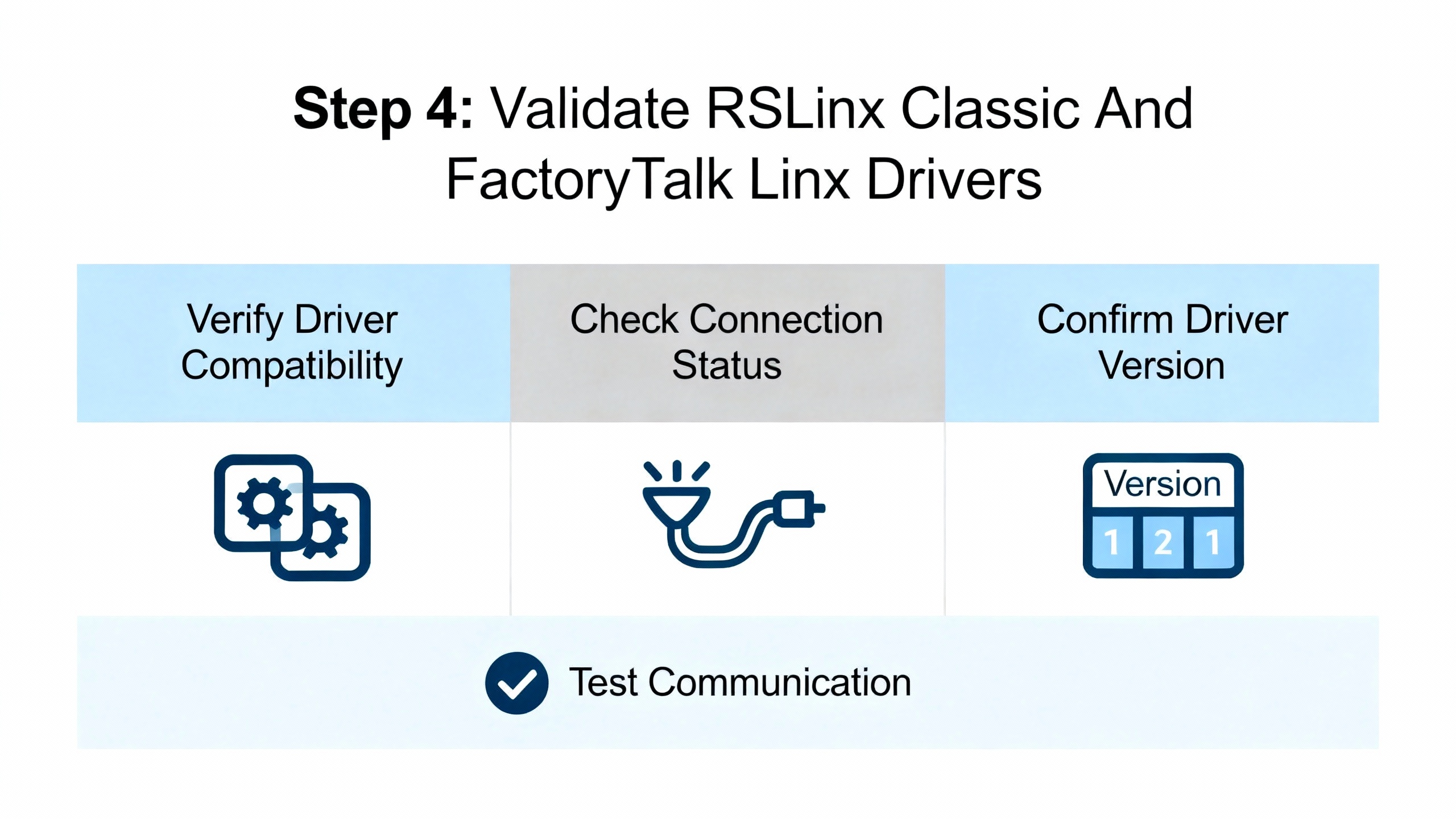
Step 4: Validate RSLinx Classic And FactoryTalk Linx Drivers
If the physical path and IP plan are correct, yet your tools still cannot see the PLC, the next focus is the Rockwell communication stack. Here, Rockwell AutomationŌĆÖs RSLinx Classic troubleshooting guidance and RealParsŌĆÖ FactoryTalk Linx examples are invaluable.
RSLinx Classic is a WindowsŌĆæbased communications server. In its interface, each communication pathway is represented by a driver. When an Ethernet driver icon shows a red X, Rockwell Automation notes that the driver is faulted, stopped, or unable to communicate. Typical causes include incorrect IP or subnet settings in the driver, use of the wrong Ethernet driver type, missing gateway configuration, and upstream network issues such as VLAN separation or routed segments without appropriate paths.
Begin by opening RSLinx Classic and inspecting the status of each EthernetŌĆærelated driver. Clear any stopped or faulted state by confirming configuration, then restarting the driver or the RSLinx service. Verify that you selected the correct driver type: Rockwell distinguishes between the newer EtherNet/IP driver and legacy Ethernet drivers, and using the wrong one can prevent browsing entirely.
RealPars shows that in FactoryTalk LinxŌĆÖs ŌĆ£Who ActiveŌĆØ view, you must enable continuous discovery on the relevant driver by turning on the ŌĆ£Make Discovery Continuous (Auto browse)ŌĆØ option when the driver node is selected. This causes the driver to send periodic discovery broadcasts and update the network tree. If you click on a specific device under the driver, discovery stops; the network view may then appear frozen even though traffic flows normally. ReŌĆæselecting the driver node restarts browsing.
RealPars also explains that the EtherNet/IP driver can bind itself to the wrong PC network adapter. If the driver is silently using WiŌĆæFi while your PLC network is on a wired adapter, discovery will fail. The remedy is to open the driverŌĆÖs configuration, go to the advanced settings, and explicitly bind it to the correct adapter. Combine this with the earlier IP alignment to ensure the driver is using an interface that sits on the same subnet as the PLC.
FactoryTalk Linx uses visual cues to indicate device status. A red X on a device means a controller or module that was previously reachable is now offline, often because its cable was unplugged or its IP address changed. RealPars suggests using the ŌĆ£Remove Offline DevicesŌĆØ function on the driver to clear stale entries, then refreshing the browse to see the true picture. A yellow question mark means the driver sees a device at Layer 3 but does not have a suitable Electronic Data Sheet. In that case, you can often rightŌĆæclick the device and attempt an EDS upload directly from the device. If that fails, download the appropriate EDS from the manufacturer and install it so the driver can interpret the device correctly.
These steps collectively restore the visibility of AllenŌĆæBradley and thirdŌĆæparty EtherNet/IP devices in the Rockwell stack, which is a prerequisite to any higherŌĆælevel troubleshooting in Studio 5000 or FactoryTalk View.
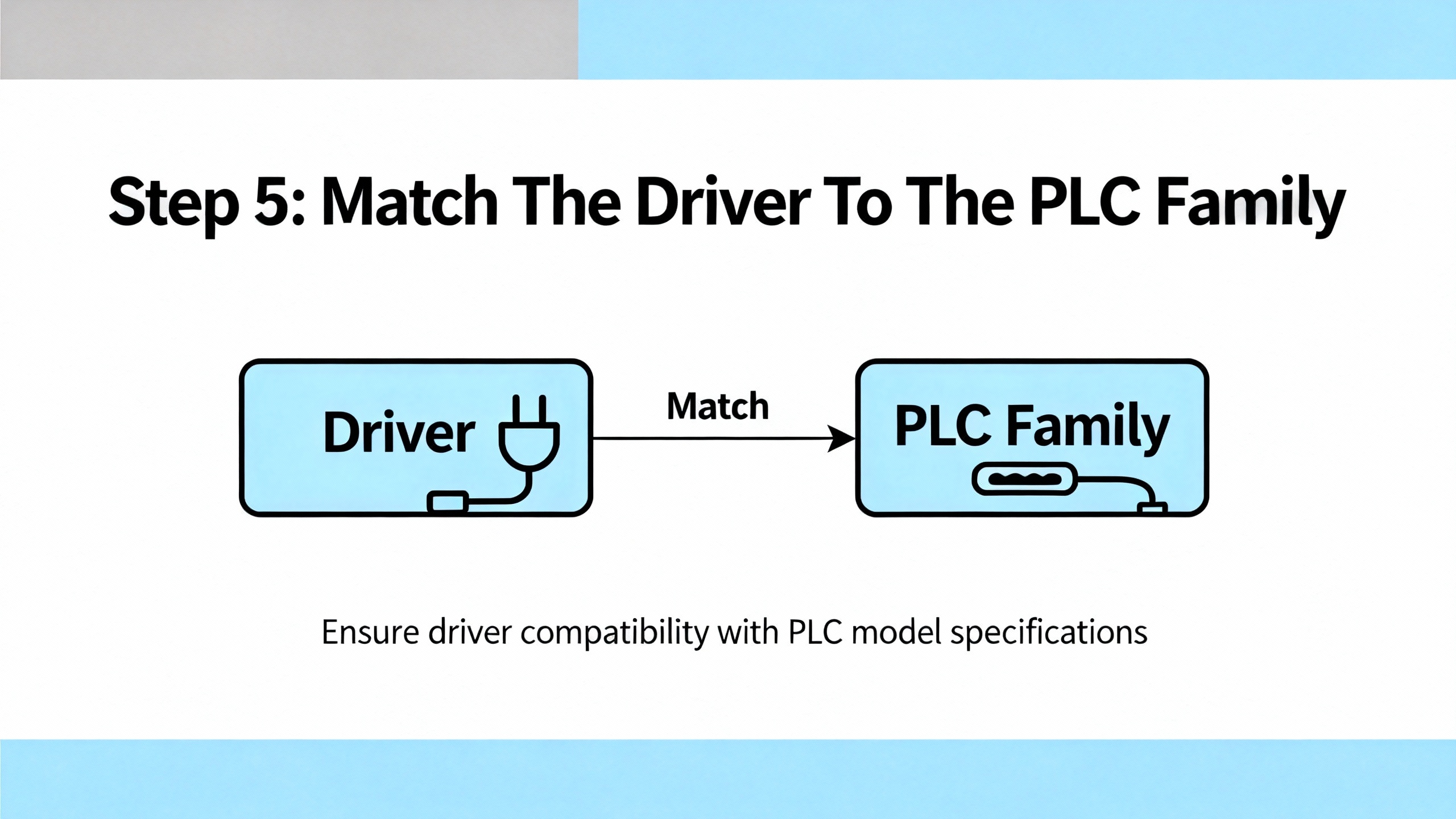
Step 5: Match The Driver To The PLC Family
Even with Ethernet drivers healthy, communication can still fail if you select a driver designed for the wrong hardware family. The Inductive Automation forum contains an instructive example: a user was unable to connect to a MicroLogix PLC because they tried to use IgnitionŌĆÖs ControlLogixŌĆæoriented driver. Community members pointed out that RSLogix 500 and RSLogix 5000, which target different AllenŌĆæBradley families, are not interchangeable. You must choose the driver that matches the actual PLC family.
The resulting guidance is straightforward. First, positively identify the controller model from its nameplate or from the onŌĆæsite programming software. Then, in your SCADA platform or engineering tool, select the protocol driver that matches that family. For Ignition, that meant using the dedicated MicroLogix driver instead of the ControlLogix driver. In RSLinx Classic and FactoryTalk Linx, the principle is similar when choosing device types and addressing schemes for older PLCŌĆæ5, SLC, or MicroLogix controllers versus LogixŌĆæseries controllers.
This matching of driver to PLC family eliminates a whole class of ŌĆ£cannot connectŌĆØ scenarios that are otherwise hard to distinguish from wiring or IP problems.
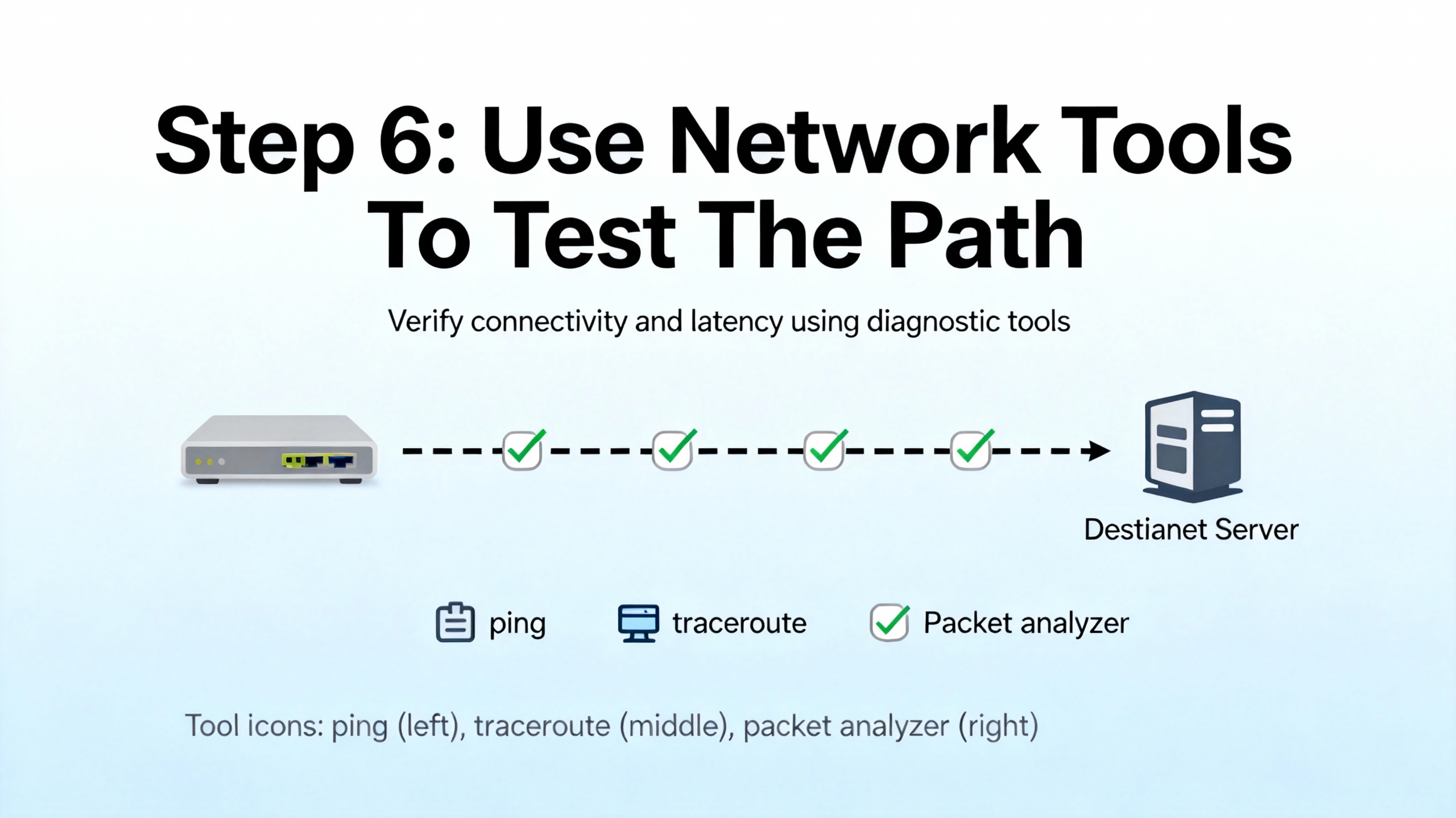
Step 6: Use Network Tools To Test The Path
At this point you have checked physical continuity, IP addressing, and Rockwell drivers. If communications are still unreliable, it is time to use network tools to see what the Ethernet path is actually doing.
IndustrialAutomationCo and RTA Automation both recommend using commandŌĆæline utilities such as ping and traceroute to verify reachability and latency. Joining the network with a laptop, assigning it to the appropriate subnet, and pinging each controller in turn will quickly reveal whether packets are reaching the PLC and whether latency or loss is unusually high. If some addresses cannot be reached while others respond normally, that points toward switch, router, or firewall rules along specific paths.
For deeper analysis, MrPLCŌĆÖs discussion of PLCŌĆæ5 Ethernet issues shows the value of Wireshark. When installed on a PC on the same network, Wireshark can capture Ethernet traffic and help you see whether the PLC stops sending or responding at the moment of dropout. Enabling promiscuous mode allows the network card to capture all packets visible on that segment, not just those addressed to the PC. Filtering on the PLCŌĆÖs IP address can then show whether it continues to send traffic during suspected outages.
However, the MrPLC case study warns that if an intelligent managed switch sits between the PC and the PLC, the PC may still only see its own traffic and broadcast messages. To overcome this, technicians sometimes insert an unmanaged hub between the PLC and the switch and connect the laptop to that hub, so Wireshark can see both directions of the conversation.
RTA AutomationŌĆÖs Ethernet troubleshooting guide adds further practical considerations. It notes that autoŌĆænegotiation between devices can fail, particularly in electrically noisy environments, leading to mismatched speed or duplex settings and intermittent errors. In such cases, disabling autoŌĆænegotiation and manually setting matching speed and duplex on both the PLC port and the switch port can stabilize the link. RTA also mentions that when a device is moved to a different switch port, stale MAC address tables can confuse forwarding until the switch is powerŌĆæcycled or its tables age out.
Taken together, these tools and techniques shift your troubleshooting from speculation to observable evidence, which is essential in powerŌĆæcritical systems where repeated outages are unacceptable.
Step 7: Watch For PLC Network Card Limits And Load Issues
Sometimes every individual piece of the network looks fine, yet controllers intermittently ŌĆ£drop offŌĆØ from some clients while others remain connected. The MrPLC Ethernet problems discussion offers an important clue in such cases: older AllenŌĆæBradley PLCs and network interface cards support only a limited number of simultaneous Ethernet connections. Community members note that newer AllenŌĆæBradley Ethernet cards support on the order of several dozen connections, but each PC or HMI can consume more than one connection, and RSLinx itself can open multiple connections to a PLC.
When the total number of connections from RSLinx, HMIs, historians, diagnostic tools, and OEM software exceeds the cardŌĆÖs capacity, new connection attempts may fail or existing ones may be dropped, making the PLC appear to vanish from view intermittently.
The recommended investigative approach, as described in that discussion, is to correlate dropouts with the number and type of clients attempting connections. Wireshark captures, RSLinx logs, and SCADA diagnostics can reveal repeated failed connection attempts or resets. A practical test is to relocate the PLC to a different network segment or test bench, load the same program, and observe whether the dropout behavior follows the PLC. If it does, that points toward PLC or card resource exhaustion or hardware issues rather than cabling or switches.
For longŌĆæterm reliability, this is where architecture and driver configuration matter. Inductive Automation forum contributors emphasize designing SCADA polling patterns thoughtfully, avoiding reading large, complex instruction blocks in highly fragmented ways, and grouping data into wellŌĆæstructured tag sets to make communications more efficient. Those are design choices that can reduce the number of separate operations and make better use of the limited connection budget.
Step 8: Consider Network Design, Segmentation, And Security
When AllenŌĆæBradley Ethernet problems recur across shifts or sites, especially in powerŌĆæcritical environments, the root cause is often the network design itself rather than a single faulty component. Rockwell AutomationŌĆÖs EtherNet/IP design guidance and MacombŌĆÖs EtherNet/IP network training materials highlight several important themes.
First, EtherNet/IP networks in industrial control systems typically carry timeŌĆæsensitive I/O and motion traffic, HMI and SCADA messaging, and integration data to higherŌĆælevel systems. To keep this traffic reliable, design guidance calls for using industrialŌĆærated, managed switches in clear control, supervisory, and enterprise zones, not unmanaged officeŌĆægrade hubs. Networks are commonly structured as stars or rings, with 100 Mbps fullŌĆæduplex segments at the device level and 1 Gbps uplinks and backbones to carry aggregated traffic. Control network utilization is typically kept well below saturation, often in the range where average load stays comfortably under a fraction of link capacity, to maintain timing margins.
Second, segmentation and quality of service matter. Rockwell and Macomb teaching materials describe using VLANs or separate physical networks to isolate control traffic from enterprise traffic, applying qualityŌĆæofŌĆæservice policies so critical CIP I/O and motion data receive higher priority than nonŌĆæcritical services such as file transfers, and avoiding uncontrolled daisyŌĆæchain topologies that complicate fault isolation.
Third, security controls now form part of reliability engineering. Rockwell and RTA Automation both stress placing control networks behind firewalls, restricting which ports are open, disabling unused switch ports, and controlling remote access through authenticated methods. IndustrialAutomationCo and RTA Automation also encourage using continuous monitoring and logging to detect abnormal traffic patterns or repeated communication failures, which can signal both cyber and physical issues.
For power system assets, this design discipline should extend to how PLCs, protection relays, UPS controllers, and battery monitoring systems share the same Ethernet infrastructure. Case studies in the IEC 61850 literature show that when protection messaging shares ŌĆ£bestŌĆæeffortŌĆØ Ethernet with other traffic, poor engineering can lead to unacceptable latency and misoperations. While IEC 61850 and EtherNet/IP are different ecosystems, the takeaway is the same: design, monitor, and periodically test the network as rigorously as you test the protection logic itself.
Step 9: Leverage Vendor And Training Resources
Even with a strong internal troubleshooting process, there are times when involving external expertise is the most reliable path. IndustrialAutomationCo and RTA Automation both recommend contacting equipment vendors for deviceŌĆæspecific issues once basic diagnostics are complete, especially when firmware, obscure error codes, or undocumented behaviors appear.
Electric NeutronŌĆÖs AllenŌĆæBradley troubleshooting guide highlights the role of Rockwell tools such as Studio 5000 Logix Designer for logic and fault analysis, RSLinx Classic or FactoryTalk Linx for communications diagnostics, BOOTPŌĆæDHCP Server for initial IP configuration, and ControlFlash or ControlFlash Plus for firmware management. These tools can also reveal deeper status on Ethernet modules, such as fault histories or diagnostic counters.
Training resources also matter for longŌĆæterm resilience. RealPars encourages structured learning around Logix communications and troubleshooting, and institutions such as Northcentral Technical College offer EtherNet/IP courses that combine networking, architecture, protocol, and security in an automation context. Rockwell AutomationŌĆÖs own EtherNet/IP configuration and troubleshooting classes provide vendorŌĆæspecific depth. For organizations running large UPS and power distribution systems, investing in this type of training for both controls and OT networking teams pays for itself quickly in reduced downtime.
Quick SymptomŌĆæToŌĆæCause Reference
The following table consolidates several common symptoms and the most likely focus areas, based on the sources discussed above.
| Symptom | Likely Focus Area | Key References (Publisher) |
| PLC does not appear in EtherNet/IP browse list | PC on wrong subnet, driver bound to wrong adapter, Auto browse disabled | RealPars, Rockwell Automation |
| Red X on Ethernet driver in RSLinx Classic | Faulted driver, wrong driver type, IP or subnet misconfiguration | Rockwell Automation |
| HMIs report ŌĆ£node not respondingŌĆØ while cabling looks OK | IP conflict, subnet mismatch, bad switch port, wrong chassis or slot map | Electric Neutron, IndustrialAutomationCo |
| Intermittent dropouts under high client load | PLC Ethernet card connection limit reached, inefficient polling patterns | MrPLC community, Inductive Automation forum |
| Single PC cannot connect, other HMIs work fine | Local firewall, disabled adapter, incorrect driver configuration | Rockwell Automation, RTA Automation |
| Multiple PLCs and HMIs go offline simultaneously | Switch, router, VLAN, or power problem in shared network infrastructure | IndustrialAutomationCo, RTA Automation, Macomb |
Use this table as a mental map: pick the symptom that best matches what you see, then concentrate your next troubleshooting step on that slice of the system.
Closing Thoughts
For a powerŌĆæcritical facility, an AllenŌĆæBradley Ethernet issue is not just an IT nuisance; it is a reliability event. A disciplined approach that starts with scope and physical checks, moves through IP and driver validation, and then leverages packet analysis, connection limits, and network design practices will resolve the majority of problems before they become crises.
If you standardize these steps across your maintenance team, document each incident, and invest in EtherNet/IP and OTŌĆænetwork training, your UPS, inverter, and protection systems will ride on a communication infrastructure that is as robust as the power hardware they control.
FAQ
How do I quickly tell if my AllenŌĆæBradley Ethernet issue is a PLC problem or a network problem?
Start by checking whether multiple independent clients have lost communication to the PLC. If several HMIs and engineering tools cannot connect, and you see link or activity LED issues or ping failures, treat it as a network problem first. If only one workstation has the issue while others are fine, focus on that PCŌĆÖs drivers, firewall, and adapter settings. RockwellŌĆÖs RSLinx Classic red X indicators and simple ping tests, as described by Rockwell Automation and RTA Automation, are very effective in making this distinction.
When should I suspect the PLCŌĆÖs Ethernet card itself?
Suspect the PLCŌĆÖs Ethernet card when the physical cabling, switch ports, and IP configuration are verified good, yet the PLC intermittently disappears from several independent clients and the behavior follows the PLC when it is moved to a different network segment. The MrPLC Ethernet problems discussion describes exactly this pattern for certain PLCŌĆæ5 Ethernet modules, especially when connection limits are reached or hardware starts to fail.
Is it worth using Wireshark in an industrial power environment, or is that overkill?
Wireshark is very useful once basic checks are done and intermittent or complex issues remain. MrPLC and RTA Automation both show that packet captures can reveal whether the PLC stops responding, whether there are repeated connection attempts, or whether traffic is being misrouted. In a power system context, where unexplained communication losses are a serious reliability concern, briefly inserting a laptop and an unmanaged hub or using a switch mirror port for captures is a reasonable and often necessary step, provided it is done under change control and safety procedures.

References
- https://www.academia.edu/86005333/Study_Using_IEC_61850_Network_Engineering_Guideline_Test_Procedures_to_Diagnose_and_Analyze_Ethernet_Network_Installations
- https://www.northwestcareercollege.edu/blog/troubleshooting-tips-for-network-connectivity-issues-for-it-technicians-part-1/
- https://www.macomb.edu/resources/workforce-development/attachments/GM-CD-Networks-EtherNet-IP.pdf
- https://www.ntc.edu/academics-training/courses/automation-systems-technology/ethernet-ip
- https://aichat.physics.ucla.edu/index_htm_files/book-search/qzAXI5/EthernetFrameHeader.pdf
- https://dowordpress.sfs.uwm.edu/exe/S46331E949/ppt/S59742E/industrial-ethernet-a_pocket-guide.pdf
- https://www.plctalk.net/forums/threads/allen-bradley-plc-and-vfd-network-issues.134723/
- https://www.electricneutron.com/troubleshooting-guide-for-allen-bradley-plcs/
- https://www.justanswer.com/computer-networking/rucs1-plc-network-troubles-shooting-little.html
- https://www.realpars.com/blog/allen-bradley-plc-troubleshooting


 Videos
 News
News Applications


Leave Your Comment