Contactor failures are rarely glamorous, but in critical power systems they are memorable. A welded compressor contactor that locks a chiller on, a fried coil that prevents a UPS from transferring to bypass, or a burned elevator hoist contactor that shuts down a building are all failures I have seen that trace back to one root cause: the contactorŌĆÖs current rating and duty were never matched to the real load.
In industrial and commercial power supply systems, especially where UPSs, inverters, and power protection equipment support critical loads, you cannot treat contactor selection as a catalog afterthought. The goal is not simply ŌĆ£will it turn onŌĆØ but ŌĆ£will it survive for years under real inrush, duty cycle, and temperature.ŌĆØ
This guide walks through how contactors are rated, what ŌĆ£60 AŌĆØ or ŌĆ£100 AŌĆØ really means, how utilization categories like ACŌĆæ1 and ACŌĆæ3 change the picture, and a practical method to choose the right current capacity. The recommendations here align with guidance from manufacturers and technical resources such as ContactorDepot, Rico Automation, C3Controls, Springer Controls, Denor, RS, RSPSupply, and others, and are framed from a reliability point of view rather than minimum compliance.
1. What Contactor Ratings Really Mean
Before talking about ŌĆ£how big,ŌĆØ it is worth being precise about what is being rated. Several sources, including Rico Automation, C3Controls, and RS, converge on the same core definitions.
A contactor is an electrically operated switch designed to make or break power circuits under load. C3Controls describes it as a specialized relay built for higher current: relays commonly handle around 5ŌĆō15 A, while contactors used in industry can carry from a few amperes up to more than 5,000 A and power levels over 100 kW, at voltages from around 24 VDC to several hundred or more volts AC. RS and C3Controls both emphasize that contactors can be controlled with modest coil power, allowing lowŌĆævoltage control of highŌĆævoltage loads.
When you read a contactor datasheet or nameplate, you are typically seeing several distinct ratings, each with different implications.
| Rating type | What it describes | Where it comes from |
| Continuous current rating | Maximum current the device can carry thermally without damage, often called thermal current | Manufacturer tests; Rico Automation notes this as the basis of many published amperage ratings |
| Utilization category (ACŌĆæ1, ACŌĆæ3, ACŌĆæ4, etc.) | Type of load and duty (resistive, motor, plugging, etc.) the contactor is tested for | IEC standards summarized by Denor, Springer Controls, RS, and Rico Automation |
| Operational voltage (Ue) | Maximum voltage at which the contactor can safely switch under its category | PPR and RS describe Ue as the safe working voltage for switching |
| Insulation voltage (Ui) | Maximum voltage the insulation system can withstand without breakdown | PPR explains Ui as a dielectric capability separate from normal operating voltage |
| Coil (control) voltage | Voltage required to energize the coil and close the contacts | Highlighted by Rico Automation, Springer Controls, RS, RSPSupply, and Kent Electrical Supply as a key selection input |
| Mechanical and electrical life | Number of operations the contactor can perform mechanically and under load | Springer Controls cites design targets around 10 million operations when used within the correct utilization category |
| Ambient temperature range | Temperature band within which ratings apply, often with derating at higher temperatures | Rico Automation notes that increased ambient temperature forces a reduction in allowable current |
From a currentŌĆæcapacity perspective, the two most important lines are the continuous current rating and the utilization category. A 60 A contactor in ACŌĆæ1 duty is not equivalent to a 60 A contactor in ACŌĆæ3 duty, even if both say ŌĆ£60 AŌĆØ on the label.
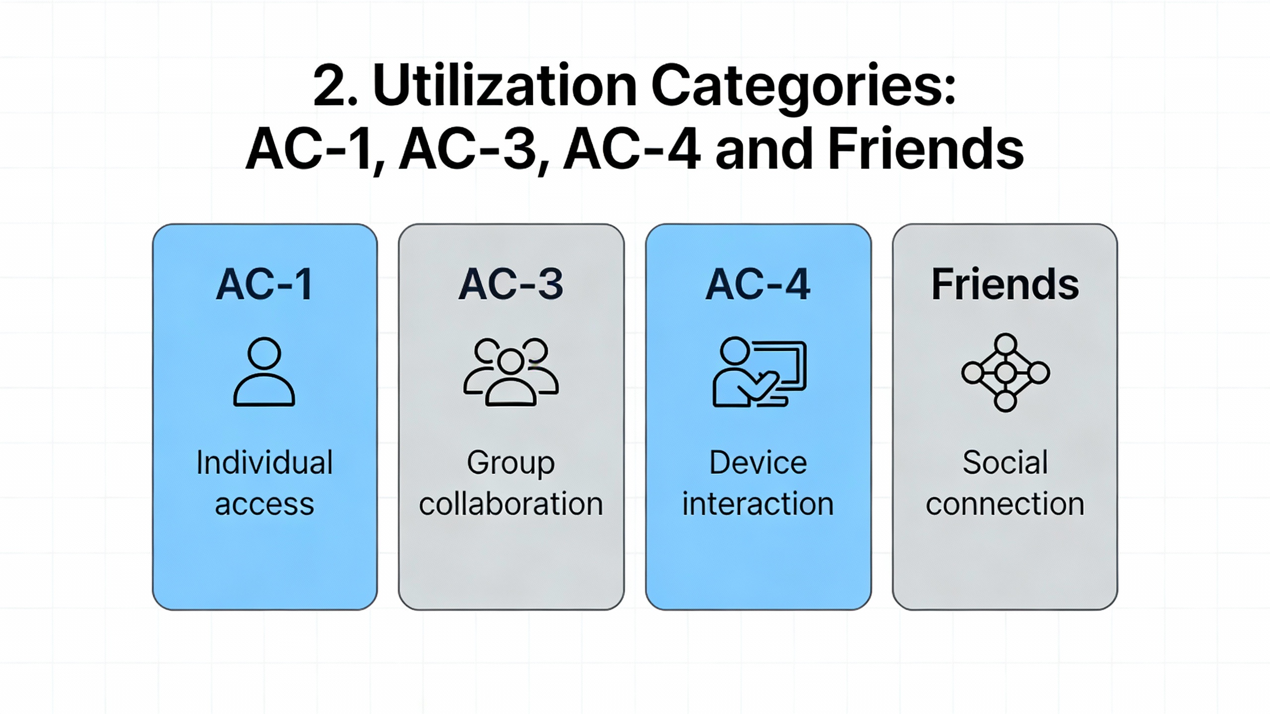
2. Utilization Categories: ACŌĆæ1, ACŌĆæ3, ACŌĆæ4 and Friends
IEC utilization categories define how hard life will be for the contacts. Denor, Springer Controls, RS, RSPSupply, and Rico Automation all echo the same basic picture.
DenorŌĆÖs overview of contactor duties notes that ACŌĆæ1 is intended for nonŌĆæinductive or slightly inductive loads such as heaters and resistance furnaces, where power factor is close to unity. Current is steady and switching is relatively gentle. ACŌĆæ3, by contrast, is the workhorse for squirrelŌĆæcage motors: starting a motor and switching it off while running, enduring high inrush currents at start and substantial inductive energy when opening under load. ACŌĆæ4 is more severe still, intended for frequent startŌĆæstop, plugging, and inching of motors, such as crane duty.
Rico AutomationŌĆÖs explanation reinforces this by grouping ACŌĆæ1, ACŌĆæ3, and ACŌĆæ4 as ŌĆ£common duty categoriesŌĆØ and tying them to specific load types: ACŌĆæ1 for slightly inductive or resistive loads, ACŌĆæ3 for starting and running motors under full load, and ACŌĆæ4 for severe applications with repetitive short bursts and high inrush. RSPSupply stresses a practical constraint: ACŌĆæ1 ratings should not be used to justify motor duty, because they do not account for inrush; ACŌĆæ3 is the right basis for squirrelŌĆæcage motor loads.
A simplified view of the main AC categories relevant to current selection looks like this.
| Category | Typical load type | Example applications (from Denor and related sources) | Selection implication for current capacity |
| ACŌĆæ1 | NonŌĆæ or slightly inductive, resistive loads | Heaters, electric furnaces, resistive lighting | Contacts see relatively low stress; published amp rating is close to thermal limit |
| ACŌĆæ2 | SlipŌĆæring motors, starting and stopping | HighŌĆætorque slipŌĆæring motor starters | Higher making current than ACŌĆæ1; must honor manufacturer data |
| ACŌĆæ3 | SquirrelŌĆæcage motors, starting and stopping while running | Lifts and elevators, conveyors, fans, pumps, compressors, mixers | Motor inrush and inductive breaking dominate; ACŌĆæ3 current rating is stricter |
| ACŌĆæ4 | SquirrelŌĆæcage motors with plugging and inching | Cranes and drives with frequent jogging or plugging | Very high stress; may require larger frame for same steady current |
| ACŌĆæ5, ACŌĆæ6, ACŌĆæ7, ACŌĆæ8 | Specialized loads (lamps, transformers, capacitor banks, hermetic compressors, small household machines) | Discharge and incandescent lighting, transformers, capacitor banks, hermetic compressors | Must match the category to the actual device; transformer and capacitor inrush can be several times full load |
For DC duties, Denor lists similar categories (DCŌĆæ1, DCŌĆæ3, DCŌĆæ5, etc.) that differentiate nonŌĆæinductive loads from shunt and series motors with starting, plugging, and braking, but for many UPS and industrial motor applications the AC categories dominate.
The key takeaway is that an ampere is not an ampere in all contexts. A 40 A ACŌĆæ1 contactor on a heater and a 40 A ACŌĆæ3 contactor on a hoist motor live entirely different lives, even if the steady current is identical.
3. StepŌĆæbyŌĆæStep Method to Choose Proper Current Capacity
Once you understand that the amp rating is tied to a specific utilization category, you can follow a structured process to choose current capacity that meets both design and reliability targets. The steps below synthesize guidance from ContactorDepot, Rico Automation, Springer Controls, RSPSupply, and Kent Electrical Supply.
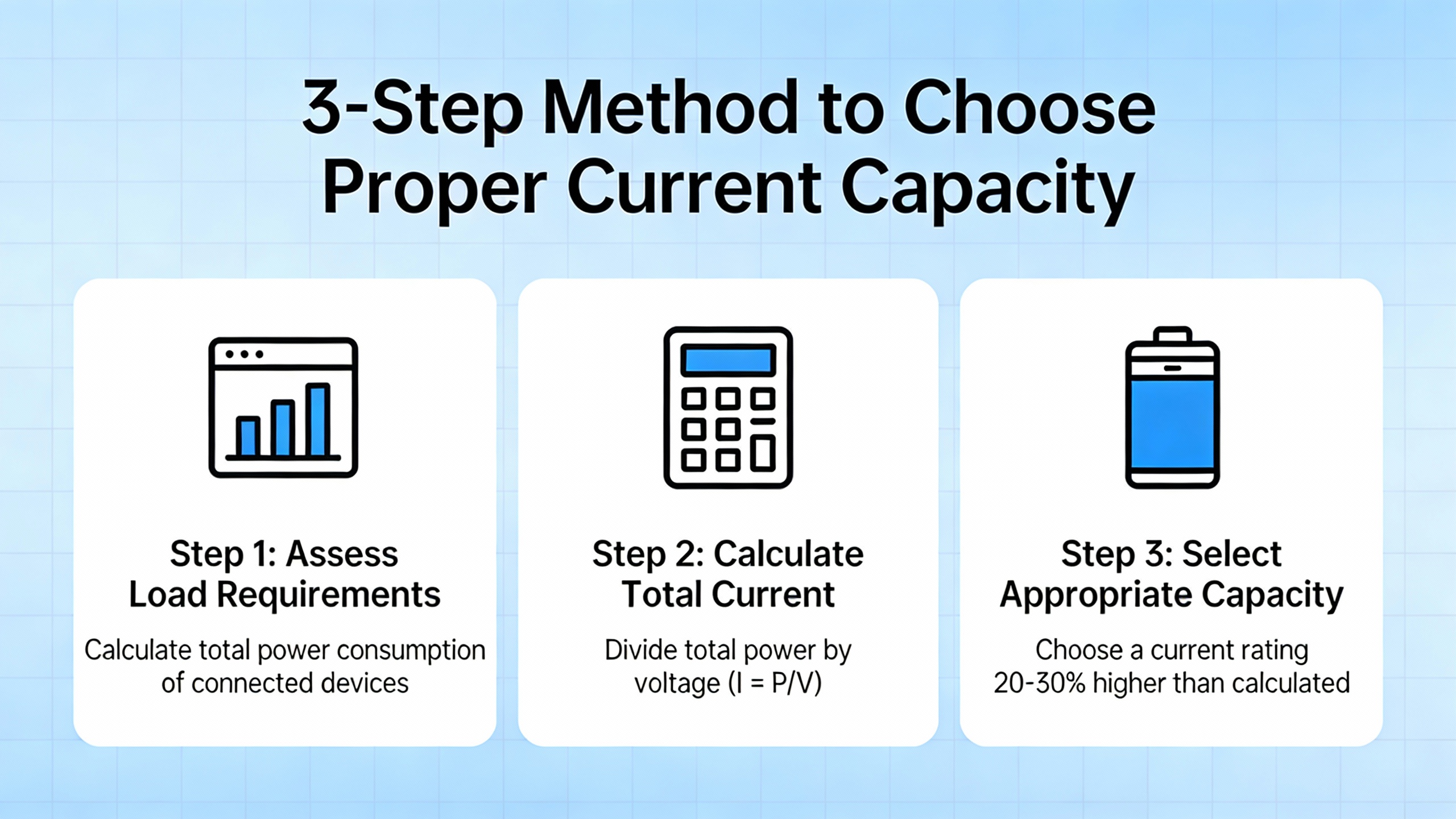
3.1 Identify real load current
ContactorDepotŌĆÖs motor sizing guide and Springer ControlsŌĆÖ IEC sizing article both begin with the same instruction: start from the loadŌĆÖs fullŌĆæload current. For motors, this is the Full Load Amperage (FLA or FLC) on the nameplate at the actual operating voltage. For other loads, it is the continuous current drawn at rated conditions, again from the equipment nameplate or datasheet.
If the motor nameplate is missing or illegible, Springer Controls notes that National Electrical Code motor FLA tables, or calculators based on them, can be used to estimate current from horsepower, voltage, and phase. For modern UPS, inverter, or rectifier systems, the manufacturer datasheet will typically state continuous input and output currents; those become your base currents when sizing contactors in those paths.
As a quick example, suppose a threeŌĆæphase compressor motor is nameplated at 52 A full load at the operating voltage. That 52 A is your starting point. For a resistive heater, perhaps the nameplate shows 36 A; that becomes your base current for an ACŌĆæ1 contactor.
3.2 Apply a margin for inrush and operating stress
Motor and inductive loads do not stop at the nameplate number. Rico Automation explicitly recommends adding roughly 20ŌĆō30% margin above fullŌĆæload current to account for starting inrush. Kent Electrical Supply, in its detailed contactor installation and sizing guidance, cites a similar concept in a slightly different form: for motor loads, choose a contactor rated at least 115% of the motorŌĆÖs fullŌĆæload current, and for equipment with high inrush and frequent starts a service factor margin of about 125% is advisable.
Kent Electrical Supply even provides a simple numerical illustration: a motor drawing 50 A at full load should drive the choice of a contactor rated for at least 57.5 A. In practice, that means stepping up to the next standard current rating above the calculated value rather than trying to match it exactly.
Returning to the 52 A compressor example derived from ContactorDepotŌĆÖs discussion of frequently cycling compressor motors, applying a 20ŌĆō25% margin suggests a target in the midŌĆæ60 A range. Rather than attempting to use a 52 A or 55 A contactor, you would look at the manufacturerŌĆÖs ACŌĆæ3 ratings and select the next frame whose ACŌĆæ3 rating comfortably exceeds the marginŌĆæadjusted current. ContactorDepotŌĆÖs guidance is clear that undersizing leads to overheating and premature wear, particularly when the compressor cycles many times per hour.
For resistive loads under ACŌĆæ1 duty, margin is still sensible, but you are generally dealing with more predictable behavior. Rico AutomationŌĆÖs advice to choose a rating above the fullŌĆæload current, with some allowance for temperature and grouping, is usually sufficient.
3.3 Match the utilization category to the load
With a target current in mind, the next filter is the utilization category.
For motors, ContactorDepot and RSPSupply both emphasize that ACŌĆæ3 is the default category for squirrelŌĆæcage motors that start under load and are switched off while running. If the application involves frequent jogging, plugging, or inching, Springer Controls and DenorŌĆÖs classification point you to ACŌĆæ4, a more severe category that can justify a larger contactor for the same FLA.
For simple heating loads, DenorŌĆÖs definition of ACŌĆæ1 as nonŌĆæ or slightly inductive, nearŌĆæunity power factor loads means you can safely apply ACŌĆæ1 ratings, assuming the circuit really is resistive. For transformer primaries, EatonŌĆÖs transformerŌĆæswitching guidance highlights that dedicated transformer categories such as ACŌĆæ6b are appropriate, because magnetizing inrush current can be several times the transformerŌĆÖs normal fullŌĆæload current. Relying on an ACŌĆæ3 or ACŌĆæ1 rating alone for that duty can be misleading.
A critical reliability point from RSPSupply is that ACŌĆæ1 ratings should not be used for motor loads. A contactor may be labeled 40 A ACŌĆæ1 and only 9 A ACŌĆæ3; sizing it to a 30 A motor based on ACŌĆæ1 would be a serious error.
3.4 Consider duty cycle and operations per hour
The electrical rating assumes a certain duty pattern. Kent Electrical SupplyŌĆÖs selection criteria, Springer ControlsŌĆÖ utilizationŌĆæcategory notes, and RSPSupplyŌĆÖs explanation of duty cycle all stress that frequent switching elevates thermal and mechanical stress on contacts and mechanisms.
RSPSupply highlights that contactors carry duty cycle ratings, sometimes expressed as allowable operations per hour (for example, a few hundred operations per hour) or as continuous versus intermittent duty. Springer Controls notes that its IEC contactors are designed for around 10 million operations when used within their proper utilization category and duty profile; pushing a device far beyond its intended operations per hour will shorten life.
The elevator hoist motor case discussed on EngŌĆæTips is a good realŌĆæworld illustration. The contactor in that system is ACŌĆæ3 rated at 30 kW and is applied to a hoist motor of roughly the same power, with measured currents of roughly 20ŌĆō30 A running and around 41.7 A starting, with the contactor operating as often as once per minute. Contacts were found heavily burned and partially melted while the coil remained intact. The contactor was technically within its nameplate limits, but it was operating near the top of its rating in a highŌĆæduty application, and that combination of high load and frequent switching drove early contact damage. The lesson is that selecting a contactor only to just meet the numeric rating, without considering operations per hour, is not enough.
For many UPS or inverter transfer contactors that operate only during rare bypass or maintenance events, duty cycle is gentle and current margin plus correct utilization category dominate. For HVAC compressors cycling every few minutes, escalators, conveyors, or crane drives, duty cycle should push you toward a more conservative current selection.
3.5 Account for ambient temperature and environment
Rico Automation calls out ambient temperature as a formal rating factor, with a clear example: a contactor rated 100 A at around 77┬░F may only be rated about 80 A if it operates near 104┬░F. In real switchboards and UPS rooms, ambient temperatures near or above that higher value are not unusual.
C3Controls and RS both note that contactors generate more heat than small relays and that permissible operating temperature ranges are important in product selection and installation. When multiple contactors are mounted side by side with limited ventilation, practical current capacity can drop further.
If you are installing a 90 A contactor in a cramped, poorly ventilated enclosure adjacent to other heatŌĆæproducing devices and the room itself regularly reaches 100┬░F or more, treating the published current rating as a hard limit is risky. Using manufacturer derating curves or tables, as Rico Automation suggests, and allowing extra margin in current capacity is prudent.
3.6 Verify coil voltage and control side integrity
Coil voltage does not directly change power current capacity, but it has an indirect effect on reliability and heating. Rico Automation, RS, RSPSupply, Springer Controls, and Kent Electrical Supply all emphasize that the coil voltage must match the control circuit.
If the coil is significantly undervoltage, the armature may chatter instead of sealing fully, causing contact bounce, excessive arcing, and localized heating. Overvoltage can overheat the coil and shorten its life or lead to failure. C3Controls notes welded contacts as a common failure mode from high inrush and unstable control voltages, and coil burn as another.
Common coil voltage offerings include values such as 24 VDC, 24 VAC, 48 V, 120 V, and 230ŌĆō240 V, typically up to around 250 V on the control side, according to RS and Kent Electrical Supply. In industrial systems it is common, as RS describes, to drive a contactor coil at 24 VDC from a control power supply while the contactor switches a much higher supply on the load side. These are excellent practices for safety and remote control, but only if the coil rating and control supply align.
4. 60 A Versus 100 A Contactor: Is Bigger Better?
One of the most frequent questions from project teams is whether to simply oversize the contactor ŌĆ£for safety.ŌĆØ The 60 A versus 100 A comparison discussed by ContactorDepot is an excellent lens for this.
ContactorDepot explains that a 60 A contactor is designed for loads up to 60 A, suited to moderate current applications where very high starting or running currents are not expected, and typically more compact and spaceŌĆæefficient. A 100 A contactor is designed to handle up to 100 A, used with larger motors and heavy industrial equipment, but physically larger and more expensive. Because of more copper and more robust construction, higherŌĆæamp contactors cost more, and their coils often consume more power.
The same article cautions that exceeding a contactorŌĆÖs ampacity risks overheating, welded contacts, and premature failure. It also warns that using a higherŌĆæamp contactor than the load requires, while technically possible, is not automatically a good idea: the oversized contactor may be less efficient, more expensive, and can have a reduced lifespan because it may not operate in its optimal range. Their core recommendation is to match the contactorŌĆÖs amp rating closely to the applicationŌĆÖs current requirement rather than always oversizing.
At the same time, the motorŌĆæcontactors discussion on the Mike Holt forum introduces a nuance. Experienced practitioners there note that stepping up one frame size from the minimum required rating can often improve durability, particularly when working with highŌĆæquality IEC brands or robust NEMA designs. They also point out that quality varies widely: some IEC contactors from vendors such as Siemens, certain Sprecher & Schuh vintage units, Mitsubishi, ABB, and others have proven very durable in demanding industrial applications, while lowŌĆæcost knockoffs with similar printed ratings can be ŌĆ£junkŌĆØ internally. The same forum thread advises caution with ŌĆ£Definite PurposeŌĆØ contactors, which are engineered for specific limitedŌĆædemand uses and are not a universal solution.
Taken together, the picture is this. Using a 100 A contactor where your adjusted ACŌĆæ3 current requirement clearly falls in the lowŌĆæ50 A range is likely excessive; a correctly chosen 60ŌĆō65 A device from a reputable manufacturer, in the correct category and with appropriate dutyŌĆæcycle consideration, is a better engineering choice. On the other hand, if margin, ambient conditions, and duty cycle push you right up against the limits of a smaller frame, stepping to the next frame size, as the Mike Holt discussion suggests, can be justified as a reliability upgrade, especially if the cost and space impact are acceptable.
A simple mental rule of thumb, consistent with both ContactorDepot and the practitioner commentary, is to size the contactor so that your actual adjusted current lands comfortably within its utilizationŌĆæcategory rating, not perched on the last few amperes, and to avoid jumping multiple frame sizes above that point without a clear reason.
5. NEMA Versus IEC and the Role of Quality
C3Controls provides a useful comparison between NEMA and IEC standards, which the Mike Holt community commentary on quality complements.
NEMA contactors, standardized for lowŌĆævoltage motors below about 1,000 V, are specified in discrete sizes (00, 0, 1 through 9) with associated continuous current and motor horsepower ratings. C3Controls points out that NEMA designs are intentionally oversized, often by safety factors up to around 25% beyond design ratings. This makes them forgiving when operating conditions such as load current or duty are not perfectly known. NEMA devices are also described as particularly capable of withstanding shortŌĆæcircuit stress, though they generally require additional safety covers to be fingerŌĆæsafe.
IEC contactors, by contrast, are defined under a global standard that offers many more size steps. They are not oversized by default, and are meant to be applied when the operating conditions are well understood. C3Controls notes that IEC contactors are typically smaller and less expensive, and are often fingerŌĆæsafe at the terminals. The tradeŌĆæoff is that they must be selected more precisely and are less forgiving of unknown or changing duty conditions.
Practitioners in the Mike Holt forum caution that today, some products bear NEMA ratings while internally resembling IEC designs, and that a NEMA label is not an automatic guarantee of exceptional robustness. They emphasize that quality varies widely among IEC contactors as well, citing Siemens, certain Sprecher & Schuh designs, Mitsubishi, and ABB as examples of highŌĆæquality IEC contactors in demanding industrial use, while warning against lowŌĆæcost offshore copies that imitate premium brands cosmetically but perform poorly.
All of this feeds directly into currentŌĆæcapacity selection. A cheap IEC contactor with a 60 A ACŌĆæ3 rating may not handle the same abuse as a wellŌĆædesigned device with the identical printed rating, especially in highŌĆæduty or highŌĆætemperature conditions. A NEMA contactor may include extra current margin by design, but counting on that hidden safety factor instead of explicitly accounting for inrush, duty cycle, and temperature is not sound engineering.
From a powerŌĆæsystem reliability perspective, especially around UPSs, inverters, and critical motors, matching the current capacity correctly and then choosing a reputable manufacturer and appropriate standard (NEMA or IEC) is far more effective than using brand alone as a proxy for margin.
6. Examples Across Typical Applications
6.1 Compressor motor in a critical cooling system
ContactorDepotŌĆÖs compressorŌĆæduty example with a 52 A motor is a classic case. A compressor that cycles frequently in a data room or process cooling application draws its fullŌĆæload current on every run and imposes high inrush currents at start. Following Rico Automation and Kent Electrical SupplyŌĆÖs guidance, you would:
First, take the 52 A fullŌĆæload current from the motor nameplate.
Second, apply a margin of at least 15ŌĆō25% for inrush and duty, yielding a target above the lowŌĆæ60 A range.
Third, ensure the contactorŌĆÖs ACŌĆæ3 rating at the operating voltage exceeds that adjusted value, and consider whether the application edges into ACŌĆæ4 territory if frequent short starts or reversing are involved.
Fourth, check the room and enclosure temperature; if the ambient can approach 100┬░F or more, use manufacturer derating information to confirm that the chosen size is still suitable, or step up one frame size if necessary.
Finally, verify coil voltage and consider auxiliary contacts for interlocks and status feedback, as described by Springer Controls and RSPSupply, so the compressor integrates cleanly with protection and monitoring.
6.2 Transformer primary switching in a power distribution panel
EatonŌĆÖs transformerŌĆæswitching guidance makes a crucial point: transformer magnetizing inrush at energization can be several times higher than fullŌĆæload current. A contactor chosen solely on thermal continuous rating or on an ACŌĆæ1 or ACŌĆæ3 label may fail prematurely if used to switch transformer primaries, as often happens in power distribution and some UPS or powerŌĆæconditioning systems.
Here, the correct approach is to:
Determine transformer kVA and primary voltage.
Consult the manufacturerŌĆÖs transformerŌĆæduty ratings, which Eaton indicates are typically given using appropriate utilization categories such as ACŌĆæ6b.
Select a contactor whose transformerŌĆæduty rating covers both the continuous fullŌĆæload current and the making capacity for worstŌĆæcase inrush, rather than simply matching fullŌĆæload current.
Ensure that switching frequency and duty cycle are understood; repeated cold energization of large transformers places far more cumulative stress on the contactor than occasional switching.
6.3 Elevator hoist motor contactor under high duty
The EngŌĆæTips case of an elevator hoist motor contactor is a strong warning about ŌĆ£just meetingŌĆØ the ACŌĆæ3 power rating. The contactor in question is ACŌĆæ3 rated for 30 kW at 500 V. The motor is a 40 hp (about 30 kW) hoist motor at 460 V, running with measured starting currents around 41.7 A and normal currents in the 20ŌĆō30 A range, switching approximately once per minute.
Even though the motor power nominally matches the ACŌĆæ3 rating, the combination of high utilization (frequent starts), slight differences in voltage, and the demanding hoist duty led to heavily burned and partially melted contacts while the coil survived. In reliability terms, this is a classically ŌĆ£underspecifiedŌĆØ situation: on paper it matches, but there is no margin for wear, manufacturing variation, or environmental stress.
The corrective actions in such a situation would be to reassess the contactor size, potentially choosing a larger ACŌĆæ3 contactor for the same motor, and to review whether the duty pattern might justify an ACŌĆæ4ŌĆæcapable device, given the severity of hoist duty. It also underscores the importance of regular inspection and preventive replacement of contact sets in similar applications, as advocated by Kent Electrical Supply and Chint Global for highŌĆæduty contactor systems.
7. Common Mistakes in CurrentŌĆæCapacity Selection
Looking across guidance from ContactorDepot, Rico Automation, RSPSupply, Springer Controls, C3Controls, and field cases, several recurrent selection errors stand out.
One frequent mistake is sizing solely on horsepower or kVA nameplate without checking the actual fullŌĆæload amperage at the operating voltage. Springer Controls specifically emphasizes using FLA rather than power alone, and RSPSupply explains that since power equals voltage times current, changing the voltage changes the current at the same power.
Another error is basing motor contactor choice on ACŌĆæ1 ratings. RSPSupply and Denor both make clear that ACŌĆæ1 is intended for resistive loads, while ACŌĆæ3 is for motors. Applying a 40 A ACŌĆæ1 rating to a motor that draws 30ŌĆō35 A is not safe, because inrush and inductive switching stresses are not accounted for in ACŌĆæ1.
Ignoring duty cycle is similarly damaging. RSPSupply warns that exceeding a contactorŌĆÖs rated operations per hour leads to arcing, heat buildup, and premature failure. The elevator hoist example is a textbook case of a device that was, in practice, asked to do more work than its rating comfortably allowed.
Ambient temperature and enclosure effects are often overlooked. Rico AutomationŌĆÖs example of a 100 A rating at roughly 77┬░F dropping to about 80 A at around 104┬░F is a reminder that a hot electrical room can, in effect, steal capacity from your contactor. C3Controls and RS both emphasize that contactors generate heat and must be operated within their specified temperature range.
Finally, there is a tendency to trust any device with the ŌĆ£right numbersŌĆØ on the label. The Mike Holt forum discussion, along with C3ControlsŌĆÖ NEMA and IEC comparison, highlight the reality that a lowŌĆæcost offshore contactor that visually mimics a premium brand may not match it in internal design or longŌĆæterm performance. When you are switching critical loads in a UPS, cooling plant, or essential motor, a slightly higherŌĆærated, higherŌĆæquality device usually pays for itself in reduced downtime.
8. Brief FAQ
Q: Is it safe to use a threeŌĆæphase contactor for a singleŌĆæphase load and assume I can use the full amp rating on one pole?
The Engineering Stack Exchange question on MNX25 contactors illustrates why this is not straightforward. Nameplates often state an ACŌĆæ1 or ACŌĆæ3 current for threeŌĆæphase use, but they do not always clarify whether the rating is per pole or for the device as a whole, especially when some poles are unused. Because the internal design, thermal paths, and test conditions vary, you should not assume that using only one pole allows you to carry the full nameplate current through that pole. The safe approach is to consult the manufacturerŌĆÖs datasheet or application notes for explicit singleŌĆæphase ratings or to use manufacturer selection tables that cover singleŌĆæphase duty.
Q: Does running a contactor well below its current rating always increase its life?
Operating below rated current reduces heating and can help, but ContactorDepot notes that gross oversizing has downsides. A 100 A contactor on a modest load may be less efficient, costlier, and may not operate in its optimal range. The Mike Holt forum commentary suggests a more balanced approach: choose a quality contactor, match the utilization category and current rating carefully to the adjusted load, and, when needed for harsh duty or high temperature, step up a single frame size rather than skipping several sizes. The goal is appropriate margin, not maximal oversizing.
Q: For reliability, which matters more: brand or extra current margin?
Both matter, and they interact. A highŌĆæquality IEC or NEMA contactor from a reputable manufacturer with a carefully chosen current rating will usually outlast a lowŌĆæquality device that is nominally oversized on paper. Practitioner experience shared on the Mike Holt forum, along with manufacturer guidance from C3Controls and Springer Controls, suggests that correct category, adequate current margin, appropriate duty cycle, and a proven design together deliver the longest life. Relying on brand alone without proper sizing, or relying on sizing numbers alone on a poorŌĆæquality device, are both risky strategies.
Closing
Choosing the proper current capacity for a contactor is not about picking the biggest number you can afford; it is about matching real load current, utilization category, duty cycle, temperature, and device quality so the contactor quietly does its job for years. In critical power and motor systems, that quiet reliability is exactly what you want. As a power systems specialist, my strongest advice is to treat contactor ratings as engineering data, not just catalog filters, and to let that discipline drive safer, longerŌĆælived installations.
References
- https://www.academia.edu/39280431/THE_IMPACT_OF_QUALITY_MANAGEMENT_SYSTEM_OF_CONTACTOR_QUALITY_PERFORMANCE_AT_A_LOCAL_POWER_STATION_IN_SOUTH_AFRICA
- https://www.ltrc.lsu.edu/pdf/STT205-ElectricalSafety.pdf
- https://digitalcommons.unl.edu/cgi/viewcontent.cgi?article=1159&context=archengfacpub
- https://digitalcommons.usf.edu/cgi/viewcontent.cgi?article=3878&context=etd
- https://faculty.slcc.edu/provost/syllabi_database/fall2025_team_1610_101.pdf
- https://hibp.ecse.rpi.edu/~connor/education/Fields/IEEEStd142_2007.pdf
- https://etd.ohiolink.edu/acprod/odb_etd/ws/send_file/send?accession=osu1657997507638259&disposition=inline
- https://digital.library.unt.edu/ark:/67531/metadc897716/m2/1/high_res_d/938565.pdf
- https://safety.ep.wisc.edu/wp-content/uploads/sites/707/2017/03/36.-2015-NFPA-70E-Copy.pdf
- https://denor.com/electrical-standards-for-contactors-ac1-ac2-ac3-ac4-dc1-dc2-dc3.html


 Videos
 News
News Applications


Leave Your Comment