Designing and operating industrial power panels for UPS systems, inverters, and sensitive electronics is not just a matter of ŌĆ£picking a breaker that looks big enough.ŌĆØ In the field, the breaker decisions that seem minor on paper are often the ones that later show up as overheated bus stabs, nuisance trips during critical transfers, or worst of all, arcŌĆæflash events during maintenance.
Guidance from sources such as Schneider ElectricŌĆÖs data center engineering teams, Delta Wye ElectricŌĆÖs decades of industrial projects, and technical references like ElectricalŌĆæWorld and Simcona consistently point to the same conclusion: disciplined breaker sizing is a core reliability decision, not an afterthought. This guide walks through how to size and select circuit breakers for industrial panels with a focus on continuous critical power applications, and how to do it in a way that protects both people and equipment.
Why Breaker Sizing Matters in Industrial Power Systems
In industrial environments, breaker sizing mistakes do not stay hidden for long. Delta Wye Electric, which reports thousands of industrial installations over more than forty years without safety incidents, ties that track record directly to rigorous breaker and panel practices combined with NFPA 70EŌĆædriven safety procedures. Their experience is echoed by OSHA data they cite: roughly four out of five electrical accidents occur during installation and maintenance, often because protective devices were misapplied or workers assumed ŌĆ£the breaker will take care of it.ŌĆØ
Improperly sized breakers cause several predictable problems. Oversized breakers allow conductors and busbars to run above their safe ampacity, so the copper or aluminum heats up while the breaker does nothing. That is why both ElectricalŌĆæWorld and Portlandia Electric emphasize the foundational rule that a breakerŌĆÖs rating must never exceed the adjusted ampacity of the connected conductors. On the other side, undersized breakers trip repeatedly under normal load, which is not only irritating but also brutal on UPS systems, inverters, and downstream electronics that are not designed for frequent hard power interruptions.
The cost dimension is just as real. Delta WyeŌĆÖs cost and ROI analysis shows that unplanned failures and arcŌĆæflash events can cost between $5,000.00 and $50,000.00 per hour of downtime, plus equipment damage, OSHA fines, and liability. In their comparison, a plant that invested approximately $7,500.00 in disciplined design and professional installation over five years ended up far better off than a ŌĆ£budgetŌĆØ installation that landed between about $35,000.00 and $180,000.00 in total cost once failures were accounted for. For critical power panels feeding UPS and inverter systems, these numbers are conservative.
Core Concepts: Ratings, Loads, and the 80% Rule
Before you can size breakers correctly, you need a precise vocabulary. The technical references from ElectricalŌĆæWorld, Schneider Electric, Nuclear Electrical Engineer, and others align on the following key concepts.
Breaker Rating, Wire Ampacity, and Load Current
A circuit breakerŌĆÖs ampere rating is the maximum current it is designed to carry continuously without tripping under defined conditions. ElectricalŌĆæWorld explains it as the trip threshold: above that current, the breaker eventually opens.
Wire ampacity is the maximum continuous current a conductor can carry without its insulation exceeding safe temperature limits. Standard ampacities for common copper sizes at typical 75┬░F to 167┬░F insulation temperature ratings are well established in the National Electrical Code (NEC) tables and are summarized in guides such as ElectricalŌĆæWorldŌĆÖs wireŌĆæsize chart and Portlandia ElectricŌĆÖs practical pairing recommendations.
Load current is simply the current your equipment actually draws. For singleŌĆæphase applications, references such as the Cable and Circuit Breaker Size Calculations paper and ElectricalŌĆæWorld compute it by dividing real power in watts by the voltage, with adjustments for power factor where needed. For threeŌĆæphase circuits, the same paper uses the wellŌĆæknown squareŌĆærootŌĆæofŌĆæthree relationship to convert total kilowatts and lineŌĆætoŌĆæline voltage into line current.
All of the credible sources stress the same critical rule: the breaker rating must never exceed the ampacity of the conductor after all derating factors are applied. GeneratorSourceŌĆÖs breaker selection guidance reinforces that point from a UL and testing perspective, noting that highŌĆæquality UL 489 moldedŌĆæcase breakers are calibrated with factoryŌĆæsealed trip systems and should not be altered in the field.
Continuous vs Noncontinuous Loads and the NEC 125% Rule
The NEC draws a clear distinction between continuous and noncontinuous loads. Schneider ElectricŌĆÖs data center blog and Nuclear Electrical EngineerŌĆÖs discussion of NEC 2014 point out that a continuous load is one where the maximum current is expected to last for three hours or more. Many industrial power supplies, UPS inputs, and control loads fall into this category, just as commercial lighting and EV chargers do in building applications.
NEC Section 210.20(A), discussed by Schneider Electric and several technical writers, requires that branchŌĆæcircuit breakers be sized for 100% of the noncontinuous load plus 125% of the continuous load. Nuclear Electrical Engineer explains why that leads to the familiar ŌĆ£80% ruleŌĆØ for standard breakers: most moldedŌĆæcase devices are listed to carry continuous load up to only about 80% of their handle rating. Because one divided by 0.8 equals 1.25, sizing the breaker at 125% of the continuous current ensures that the actual continuous current is only 80% of the breakerŌĆÖs nameplate.
Several examples across the references illustrate this. In the Nuclear Electrical Engineer example, a purely continuous 13.7 amp load requires a breaker rated at least 13.7 times 1.25, which is 17.125 amps. Because you must use standard ratings such as 15, 20, or 25 amps (as listed in NEC 240.6 and summarized by ElectricalŌĆæWorld), the next standard size of 20 amps is chosen. When a 4 amp noncontinuous load is added, the requirement becomes 13.7 times 1.25 plus 4, or 21.125 amps, and the next standard breaker is 25 amps.
Portlandia Electric applies the same logic in a more general chart, noting that standard breaker ratings typically support about 80% of their handle as a maximum continuous load. In practice, this means a 15 amp breaker is treated as safe for 12 amps continuous, a 20 amp breaker for 16 amps, a 30 amp device for 24 amps, and so on.
EightyŌĆæPercent vs OneŌĆæHundredŌĆæPercentŌĆæRated Breakers
The 80% limitation is not universal. Schneider ElectricŌĆÖs data center guidance and SimconaŌĆÖs industrial breaker selection article both highlight the existence of 100%ŌĆærated circuit breakers that are specifically listed to carry their full nameplate current continuously. Where such breakers are used and installed per their manufacturer instructions, the NECŌĆÖs 125% adder for continuous load sizing does not apply in the same way; the breaker is allowed to operate at 100% of its rating for continuous loads.
There are tradeŌĆæoffs. Schneider Electric notes that 100%ŌĆærated breakers typically cost more per unit, but because they can be loaded to their full rating, they may allow smaller frame sizes in circuits with significant continuous loads. That can offset cost by reducing enclosure size and conductor size. Simcona observes that standard breakers are usually rated for ambient panel temperatures up to about 122┬░F, while some 100%ŌĆærated devices are designed to operate up to around 140┬░F, which can be relevant in tightly loaded UPS rooms or hot mechanical spaces.
Schneider Electric recommends first classifying loads as continuous or noncontinuous and, where possible, segmenting circuits so each branch is predominantly one type. If a branch feeds only noncontinuous loads, standard 80%ŌĆærated breakers sized at 100% of the calculated load are usually the most economical. Where continuous loads dominate, particularly in critical power distribution, engineers should consciously compare an upsized 80%ŌĆærated breaker and conductors against a 100%ŌĆærated device and smaller conductors to see which option offers the better blend of cost, space, and future capacity.

Sizing Industrial Branch Breakers: A Practical Method
Across ElectricalŌĆæWorld, Portlandia Electric, and several engineering notes, the method for sizing branch breakers is remarkably consistent. The details differ slightly between residential examples and industrial power panels, but the logic is identical.
First, determine the load current. For each piece of equipment, pull real power and voltage from the nameplate or specification sheet and convert to amps. ElectricalŌĆæWorld uses a simple example of a 4,500 watt electric water heater on 240 volts drawing 18.75 amps. The Cable and Circuit Breaker Size Calculations paper demonstrates both singleŌĆæphase and threeŌĆæphase calculations, including a threeŌĆæphase example where a 6.5 kilowatt load on a 480 volt system draws approximately 7.82 amps per phase. For industrial UPS and inverter feeders, the same math applies; you simply plug in the appropriate voltages and kilowatts.
Second, classify each load as continuous or noncontinuous. A UPS that stays online around the clock, a dc charging system, or a process control cabinet that never shuts down is most naturally treated as a continuous load under the NEC definition. A maintenance receptacle or an occasional test charger would generally be noncontinuous.
Third, apply the 125% factor to the continuous portion. ElectricalŌĆæWorldŌĆÖs example for the 4,500 watt water heater treats it as continuous. The 18.75 amp load is multiplied by 1.25 to yield 23.44 amps as the minimum breaker capacity. For a mixedŌĆæload circuit, PortlandiaŌĆÖs example of 13 amps continuous plus 7 amps noncontinuous would lead to 13 times 1.25 plus 7, or 23.25 amps.
Fourth, apply derating factors for conditions that reduce conductor ampacity. ElectricalŌĆæWorld provides temperature derating values showing that at ambient ranges around the midŌĆæ90s┬░F, copper conductors might have their ampacity multiplied by around 0.91, dropping to roughly 0.58 by the low 120s┬░F. They also document conduit fill derating: with more than three currentŌĆæcarrying conductors in a raceway, ampacity must be reduced with factors such as 0.80 for four to six conductors, 0.70 for seven to nine, and so on.
Fifth, select a wire size whose adjusted ampacity exceeds the required load. ElectricalŌĆæWorld and Portlandia converge on typical copper pairings for 75┬░FŌĆæclass terminations: 14 AWG for 15 amp breakers, 12 AWG for 20 amps, 10 AWG for 30 amps, 8 AWG for 40 amps, 6 AWG for 50 to 60 amps, and 4 AWG for around 80 amps. Portlandia emphasizes that when conductor ampacity falls between standard breaker sizes, you generally round the breaker down to the next lower standard rating to keep the conductor conservatively protected, unless a specific NEC exception applies.
Finally, select the breaker size and type. ElectricalŌĆæWorldŌĆÖs stepŌĆæbyŌĆæstep process ends by choosing a standard breaker rating from NEC 240.6 that both protects the chosen wire and satisfies the load requirement. For the 18.75 amp continuous heater example, 23.44 amps is the minimum; 12 AWG copper at roughly 25 amps ampacity is adequate, and a 25 amp breaker is selected. In an industrial UPS panel, the same approach would be used for each feeder: calculate adjusted load, pick the conductor, and then choose a breaker whose rating does not exceed the adjusted ampacity.
Special Case: Motor and Drive Circuits in Industrial Panels
Motors and drives behave differently under fault and start conditions, and every serious source addresses them separately. ElectricalŌĆæWorld, Portlandia Electric, AutomationDirectŌĆÖs industrial breaker tutorial, and NEC Article 430 all speak to this.
Motors draw high inrush current when starting. AutomationDirect demonstrates that in the United States, NEC Table 430ŌĆæ152 often leads to inverseŌĆætime circuit breakers sized at up to 250% of the motorŌĆÖs fullŌĆæload amps, precisely to ride through that starting surge. ElectricalŌĆæWorld describes a general method for multiple motors: size the circuit capacity as 125% of the largest motor fullŌĆæload current plus the sum of the others. In all cases, conductor sizing for motor circuits tends to be based on 125% of motor fullŌĆæload current, while the overcurrent protective device can be higher, within NEC limits, to avoid nuisance tripping.
This is directly relevant in panels that combine UPS feeders with motor control centers, compressor drives for cooling, or pump loads. A feeder that supplies both continuous UPS load and intermittent motor or HVAC load must be sized in a way that respects both the continuous 125% rule and the special motor allowances. In practice, this often means separating highŌĆæinrush motor circuits into their own feeders and leaving UPS and inverter circuits on more ŌĆ£cleanŌĆØ continuousŌĆæonly feeders to simplify both breaker sizing and coordination.
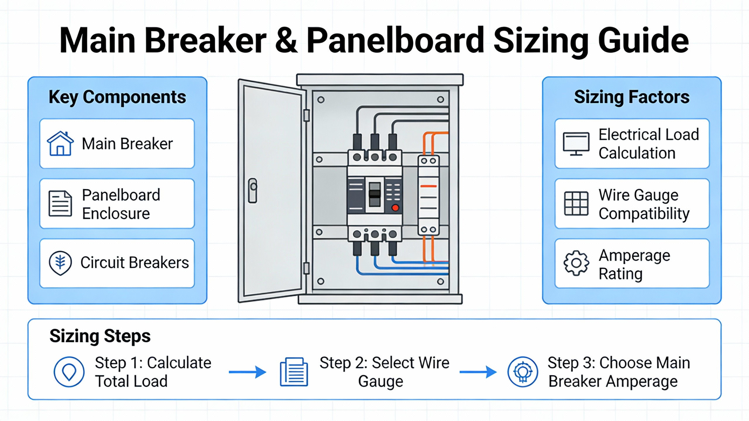
Main Breaker and Panelboard Sizing
Branch breakers protect individual circuits. Main breakers and the panelboards themselves must be sized based on the overall demand, not just by summing the numbers on the handles.
Delta Wye Electric notes that industrial facilities typically operate panels at around 70% to 80% of their rating. In their planning, available capacity is often treated as the panelŌĆÖs nominal rating minus the connected load adjusted for demand factors and the 125% continuous requirement. ThreeCrownŌĆÖs panel sizing guide for buildings, though focused on residential and light commercial, reinforces this approach by stating that continuous loads should stay below about 80% of the panelŌĆÖs rating and by warning that undersized panels lead to overloaded circuits, frequent breaker trips, and fire risk.
For existing facilities, the Mike Holt forum discussion and the EngŌĆæTips thread on main breaker sizing under the Canadian Electrical Code converge on the importance of true demand calculations. The EngŌĆæTips contributors point out that if every panel calculation conveniently lands at neat multiples such as 100 amps, 200 amps, or 300 amps, it is a red flag that someone may be guessing based on breaker handles rather than applying the demand factors in the code. They also remind designers that busbar ampacity can limit the maximum permissible main breaker size and that you cannot simply supply 700 amps of calculated demand through a 600 amp main unless very specific motor load exceptions are legitimately applied.
On the equipment side, SchneiderŌĆæaligned technical notes from ElectricalŌĆæInstallation.org describe main breaker selection for a transformerŌĆæfed installation. For a 250 kilovoltŌĆæampere transformer at 400 volts threeŌĆæphase with a fullŌĆæload current around 360 amps and a threeŌĆæphase shortŌĆæcircuit current of about 9 kiloamps, their example selects a moldedŌĆæcase breaker with an adjustable trip range of 160 to 400 amps and a shortŌĆæcircuit breaking capacity of 50 kiloamps. For larger transformers or multiple transformers in parallel, the same reference shows that feeder breakers connected closest to the common bus may see the highest fault currents and must be chosen accordingly.
For critical power panels fed from UPS output transformers or generatorŌĆæsupplied switchboards, the implication is clear. You size the main breaker for the worstŌĆæcase demand and future growth, apply the same 125% continuous logic where applicable, and then verify that its shortŌĆæcircuit rating and the busbar ampacity are adequate for the maximum fault contribution from all sources, including utility, generator, and inverter.
Fault Duty, Interrupting Capacity, and Coordination
Selecting a breaker only by its ampere rating is one of the more dangerous shortcuts in industrial practice. GeneratorSource, Simcona, ElectricalŌĆæInstallation.org, AutomationDirect, and EŌĆæTŌĆæA all emphasize interrupting capacity and coordination as equally important dimensions.
Interrupting capacity, sometimes called AIC (ampere interrupting capacity), is the maximum fault current a breaker can safely interrupt without destroying itself. GeneratorSource explains that if a breakerŌĆÖs interrupting rating is below the available fault current at its point of installation, the device can fail violently during a short circuit. Simcona notes that as facilities add more large loads and sources, basic 10 kiloamp ratings are often insufficient, and moldedŌĆæcase breakers are commonly chosen with much higher breaking capacities.
ElectricalŌĆæInstallation.org sets out the fundamental rule for lowŌĆævoltage installations: a circuit breaker must either have a rated shortŌĆæcircuit breaking capacity at least equal to the prospective shortŌĆæcircuit current at its location, or it must be part of a coordinated scheme in which an upstream device limits the energy seen by the breaker and the conductors. That coordinated technique, often called cascading, can involve combining currentŌĆælimiting breakers or fuses upstream with standard breakers downstream, allowing you to use more modest breaking capacities at lower cost while still respecting thermal and mechanical limits.
AutomationDirectŌĆÖs industrial tutorial adds important nuance around UL categories. UL 489 breakers are fully rated for branchŌĆæcircuit protection of conductors, control panels, and motor control centers and can have interrupting capacities up to about 100,000 amps. UL 1077 devices, by contrast, are only supplemental protectors and must not be relied upon as the sole means of branchŌĆæcircuit protection. When panels for UPS, inverters, and automation equipment are assembled, mixing UL 1077 devices where UL 489 breakers are required is a serious error.
Tripping characteristic also matters. ElectricalŌĆæInstallation.org and AutomationDirect both describe standardized instantaneous trip types. Type B breakers trip at roughly three to five times their rated current and are suited to sources with low fault currents, such as some generator supplies or long cable runs. Type C, typically tripping at five to ten times rating, is considered generalŌĆæpurpose and suits many distribution circuits. Type D, which may allow ten to twenty times rated current before tripping instantaneously, is used for circuits with high inrush such as motors and transformers. For many UPS and inverter output circuits with limited fault current capability, the choice of curve type and upstream coordination becomes critical to ensure that faults clear quickly without relying on fault levels the source cannot produce.
Environment, Temperature, and Derating
Industrial panels do not live in ideal laboratories; they live in compressor rooms, battery rooms, rooftop enclosures, and highŌĆæelevation plants. That reality drives derating.
ThermalŌĆæmagnetic breakers with uncompensated thermal trips, as described in ElectricalŌĆæInstallation.org, have trip currents that vary with ambient temperature. If a breaker calibrated at around 86┬░F is installed in a boiler room that runs closer to 140┬░F, the current needed to cause an overload trip can be significantly lower than the handle rating. Manufacturers provide derating tables that quantify this effect. In a detailed example for a modular iC60 breaker, a 40 amp unit derates to 38.2 amps at about 140┬░F ambient. When the same device is mounted sideŌĆæbyŌĆæside with others in a closed distribution box, mutual heating requires another derating factor of about 0.8, leaving an effective continuous capability of roughly 30.5 amps. For a load that needs 34 amps, this breaker is inadequate. The recommended solution in that example is to move up to a 50 amp breaker, which derates to about 47.6 amps at temperature and then to around 38 amps after the mutual heating factor, providing enough margin for the 34 amp load.
Compensated thermalŌĆæmagnetic devices include a bimetal compensating strip so the overload setting stays accurate over a defined ambient range, often from about 23┬░F up to around 104┬░F. Many lowŌĆævoltage breakers up to about 630 amps use such compensated tripping units, which is why service entrance breakers that enforce contractual current limits, as described in ElectricalŌĆæInstallation.org, can remain accurate across seasons.
Electronic trip units are far less sensitive to ambient temperature. ElectricalŌĆæInstallation.org highlights that electronic units offer stable performance as temperature changes, although the switchgear itself still imposes limits. Manufacturers publish operating charts that show permissible trip settings versus ambient temperature. Electronic units also frequently support energy metering and power quality functions, which can be helpful when you are trying to understand thermal loading on UPS panels or harmonics from inverters.
GeneratorSource and Simcona both raise additional environmental concerns. At altitudes above about 6,000 feet, thinner air reduces both heat dissipation and dielectric strength; breakers must be derated for current, voltage, and interrupting capacity, and the same is true for generators and other power equipment. In wet or corrosive environments, GeneratorSource recommends special moisture treatments, space heaters in enclosures, or relocating breakers out of the corrosive zone. ShockŌĆæresistant designs, including those used by the U.S. Navy with inertia counterweights, address highŌĆæshock applications. All of these factors must be considered when sizing and selecting breakers for industrial panels in harsh settings.
Safety, Installation Quality, and Commissioning
Even the bestŌĆæsized breaker will not protect your industrial panel if it is installed or maintained poorly. Delta Wye ElectricŌĆÖs guidance and NFPA 70E requirements paint a consistent picture.
NFPA 70E requires a formal electrical hazard assessment before work begins. That includes determining the arcŌĆæflash boundary, assessing incident energy levels, and selecting appropriate personal protective equipment for the voltage and energy level. Delta Wye emphasizes that OSHA statistics show about 80% of electrical accidents occur during installation and maintenance and link this pattern to weak lockout/tagout practices, incorrect PPE, and failure to verify a true zeroŌĆæenergy state.
Proper lockout/tagout for breaker work follows OSHA 1910.147 and NFPA 70E. Panels should be deŌĆæenergized and all isolation points locked. Each worker applies their own lock, and a qualified person verifies isolation with a tested voltage detector. The work area is then secured with barriers and warning signs. These steps may feel unrelated to breaker sizing, but in practice, panels that are sized and arranged well are far easier to deŌĆæenergize selectively and to work on with clear isolation points.
Mechanical installation quality is just as important. Delta WyeŌĆÖs recommended process includes inspecting panel conditions for burn marks, corrosion, overheated breakers above roughly 140┬░F, mixed breaker brands, and inadequate working space. Conductors must be prepared correctly, including verifying strip length and using antiŌĆæoxidant compounds for aluminum. Terminals must be torqued to the manufacturerŌĆÖs specifications; both Delta Wye and GeneratorSource warn that overŌĆætorquing can cause hidden damage while underŌĆætorquing leads to hot spots. After installation, panel directories must be updated as required by NEC 408.4 with specific equipment descriptions instead of vague labels.
Commissioning best practice combines visual and mechanical checks with electrical tests. Delta Wye recommends insulation resistance testing, aiming for values on the order of at least one megohm per 1,000 volts, contact resistance checks, primary injection to verify trip curves and coordination, staged load tests, and thermal imaging during early operation to identify hot spots that exceed roughly a 40┬░C temperature rise. EŌĆæTŌĆæAŌĆÖs white paper on breaker selection reinforces that field test results often deviate from factory data due to differences in temperature, altitude, and test equipment, and points to NEMA AB4 as a guide for field testing procedures.
All of this bears directly on UPS and inverter panels. A beautifully computed breaker size will fail in practice if a lug is loose, if the device is misŌĆæmounted, or if someone later replaces it with a similarŌĆælooking breaker from a different manufacturer that does not have the same interrupting capacity or trip characteristics.
Application Notes for UPS, Inverters, and Power Protection Panels
Critical power panels feeding UPS systems, inverters, and power protection equipment combine several of the challenges already discussed: high continuous loading, sensitive electronics, and sometimes unusual sources such as generators.
Continuous loading is the dominant theme. Schneider ElectricŌĆÖs explanation of the 125% rule for continuous loads and Portlandia ElectricŌĆÖs clarifications about the 80% rule make it clear that any circuit expected to run near full load for several hours at a time should be treated as continuous. In practice, the input feeders to large UPS systems, the output feeders to distribution panels that remain energized around the clock, and many dc charging circuits for battery systems behave like the commercial lighting and EV charging loads described in those references. Using the 125% sizing factor and enforcing the 80% continuous limit on standard breakers is the conservative, reliabilityŌĆæoriented approach.
The choice between 80%ŌĆærated and 100%ŌĆærated breakers is particularly relevant for compact UPS distribution where panel space and conductor sizes are constrained. Schneider ElectricŌĆÖs cost analysis for data center circuits shows that 100%ŌĆærated breakers, though more expensive individually, can sometimes reduce overall project cost by permitting smaller frames and conductors, especially where loads are clearly continuous. Simcona adds that 100%ŌĆærated devices are designed for higher ambient temperatures, which often better reflects the thermal reality inside UPS and PDU cabinets.
Frequency and source considerations matter when UPS systems are backed by generators. GeneratorSource notes that moldedŌĆæcase breakers up to around 600 amps can usually operate between 50 and 120 hertz, but at higher frequencies they must be derated due to additional heating from eddy currents and iron losses. Larger breakers with transformerŌĆæheated bimetal trips are typically calibrated for 60 hertz and may require special adjustments at 50 hertz, while solidŌĆæstate trip breakers are often preŌĆæcalibrated for a specific frequency. Coordinating with the breaker manufacturer and generator supplier is essential when you are designing automatic transfer schemes with UPS and inverter equipment.
Fault current levels in UPS and inverter systems can also deviate from simple utilityŌĆæfed assumptions. While the sources discussed here do not delve deeply into the shortŌĆæcircuit characteristics of UPS systems, the general principles from ElectricalŌĆæInstallation.org, Simcona, and AutomationDirect still apply: you must know the maximum fault current available at each panel location, from all sources, and select breaker interrupting capacities and trip curves accordingly. Where fault currents are limited by inverters, you may depend more heavily on upstream devices or specialized protective schemes, and you must avoid assuming that a breaker will clear a fault if the source simply cannot drive the needed fault current.
Finally, panel layout and future flexibility deserve attention. The Mike Holt forum discussion on breaker arrangement, while centered on smaller panels, makes points that scale to industrial UPS and PDU applications. Leaving extra conductor length in panels, avoiding the temptation to cluster only large breakers near the main lugs, and preserving key positions for equipment that genuinely requires specific locations (such as transfer interlocks or surge protection devices) all support safer maintenance and future modifications. Clear circuit labeling, as required by NEC and highlighted by Delta Wye, makes it far easier to isolate the correct UPS or inverter feeder quickly when something goes wrong.

Frequently Asked Questions
Can I size a breaker by simply matching it to the UPS or inverter nameplate current?
The technical references consistently say no. ElectricalŌĆæWorld, Nuclear Electrical Engineer, and Schneider Electric all stress that you must apply the 125% rule for continuous loads, use demand factors where appropriate, and check conductor ampacity and derating. For a continuous UPS input or output, you start with the nameplate current, multiply by 1.25, consider environmental derating, select conductors whose adjusted ampacity exceeds the result, and then choose a standard breaker whose rating does not exceed that ampacity. Simply matching the handle to the nameplate ignores code requirements and usually offers no margin for ambient temperature or future growth.
When is it worth paying for 100%ŌĆærated breakers in industrial panels?
Schneider ElectricŌĆÖs data center guidance and SimconaŌĆÖs industrial selection notes suggest that 100%ŌĆærated breakers are most attractive where you have heavy continuous loading, constrained space, and controlled ambient conditions. In a UPS distribution panel where most feeders are continuous, a 100%ŌĆærated breaker can allow you to use a smaller frame and conductors while still complying with NEC, yielding savings in copper, enclosure size, and sometimes labor. However, they require specific installation conditions, including enclosure ratings and thermal management, and they cost more. Where loads are mixed or noncontinuous, standard 80%ŌĆærated breakers are often more economical.
How much spare capacity should I leave in an industrial panel feeding critical power loads?
Delta WyeŌĆÖs planning practice of operating panels at about 70% to 80% of their rating and ThreeCrownŌĆÖs panel guide both support leaving a meaningful capacity margin. You start with proper demand calculations, including the 125% continuous adjustment, and then choose a panel and main breaker large enough that your calculated demand does not exceed roughly 80% of the panelŌĆÖs rating. This provides room for reasonable future growth and reduces the risk of running busbars and breakers near their thermal limits. For facilities with rapidly evolving loads such as data centers, it is common to deliberately oversize main distribution for anticipated expansions, a practice that is reinforced in the Mike Holt and EngŌĆæTips discussions.
Reliable industrial power for UPS systems, inverters, and protection equipment depends on decisions made months or years before the first breaker is switched on. By grounding your breaker sizing in the NECŌĆÖs 125% rule, matching breakers to conductor ampacity, respecting interrupting capacity and environmental derating, and commissioning with the rigor described by NFPA 70E practitioners and longŌĆætime industrial contractors, you turn your panels from weak links into robust, predictable parts of the power chain. As a reliability advisor, that is the standard I recommend aiming for on every project.
References
- https://www.academia.edu/85212475/Cable_and_Circuit_Breaker_sizes_Calculations
- https://weh.maritime.edu/EN-3111/references/ABB-2218-WPO_Circuit_breaker_ratings.pdf
- https://www.osti.gov/servlets/purl/1660681
- https://www.law.cornell.edu/cfr/text/30/75.601-1
- https://doa.wi.gov/DFDM_Documents/MasterSpecs/Electrical/ElectricalGuidelines.pdf
- https://eta-publications.lbl.gov/sites/default/files/2024-10/electric_service_sizing_technical_brief_2024072_kj-ls.pdf
- https://www.aro.pitt.edu/aro/sd/Rooms/RoomComponents/LoginView/GetSessionAndBack?redirectBack=https%3A%2F%2Fassets-global.website-files.com%2F675480bd94017831e9ea8d56%2F6803f15d321b2ce866b3159e_pelotikinutu.pdf
- https://www.seattle.gov/documents/departments/spu/engineering/dsg/2024/9cdesigncalculationsforelectricaldesign.pdf
- https://www.electrical-installation.org/enwiki/Selection_of_a_circuit-breaker
- https://pacbasics.org/circuit-breaker-sizing-calculation-a-step-by-step-guide/


 Videos
 News
News Applications


Leave Your Comment