Bently Nevada proximity probes sit in a harsh place between high-speed steel and high-stakes production. When they fail, you do not just lose a sensor. You risk losing protection on turbines, compressors, generator drives, and the power systems that depend on them. As someone who has spent years keeping industrial power and protection systems online, I can say that most ŌĆ£bad probesŌĆØ I get called for are not actually failed sensors. They are wiring, configuration, or installation issues that look like sensor failure.
This guide walks through how to distinguish true Bently Nevada proximity probe failure from system problems and, when the probe is really bad, how to replace it correctly. The focus is on common systems such as 3300 XL 8 mm and 3300 NSv probes, used for shaft vibration and position on critical rotating machinery feeding industrial power and UPS-backed loads.
The goal is simple: restore reliable protection without creating a ŌĆ£FrankensteinŌĆØ measurement chain that quietly erodes your machinery protection and power system reliability.
Why Proximity Probe Health Matters To Your Power System
In a modern plant, vibration probes are not just instrumentation. They are a protection device in the same sense as a circuit breaker or UPS bypass contactor. Bently Nevada proximity probes feed condition monitoring racks that initiate alarms and trips when vibration or shaft position crosses safe limits. Baker Hughes, the manufacturer, emphasizes that these systems are a first line of defense against unbalance, misalignment, rubs, fluid instabilities, and other serious faults that can destroy rotating equipment if left undetected.
The stakes are not theoretical. As Omron points out for stamp and weld lines in automotive production, a single collision can destroy an end effector worth tens of thousands of dollars and bring a millionŌĆædollar stamping die to a halt. In the same way, a failed or misapplied proximity probe on a turbine or compressor can lead either to nuisance trips that hit production and power quality, or to missed trips that allow a failure to propagate into catastrophic damage.
For power-system operators, this directly affects:
Reliability, because protection systems that go ŌĆ£Not OKŌĆØ leave turbines, generator drives, and large motors partially unprotected.
Power quality, because trips and forced outages ripple into UPS load transfers, inverter cycling, and voltage disturbances.
Maintenance cost, because misdiagnosed sensors waste time and money while leaving the underlying problem unresolved.
Treating Bently Nevada proximity probes as critical protection assets, not just small pieces of coaxial hardware, is the first step toward a disciplined replacement strategy.

How A Bently Nevada Proximity Probe System Works
Before you decide a probe has failed, it helps to understand what ŌĆ£normalŌĆØ looks like.
A Bently Nevada proximity transducer system consists of three tightly matched components: the probe mounted at the machine, the extension cable, and the driver or Proximitor module. Sources such as Baker Hughes and Amikong emphasize that these three pieces are engineered and calibrated as a set, not as interchangeable parts. Swapping one piece for a different model or brand changes the electrical behavior and can distort every reading the rack sees.
The working principle is eddy current displacement sensing, as described by Instrumentation and Control Engineering and Baker Hughes:
The Proximitor generates a highŌĆæfrequency radioŌĆæfrequency signal and sends it down the extension cable to a coil in the probe tip.
The coil creates an electromagnetic field in front of the probe. When a conductive shaft surface enters this field, eddy currents are induced in the metal.
Those eddy currents absorb energy. The closer the shaft surface moves to the probe, the greater the energy loss.
The Proximitor senses that loss and converts it into a DC voltage proportional to the gap between the probe tip and the shaft plus an AC component representing vibration.
Two outputs matter in practice. The DC component is the gap voltage, a negative value that represents average shaft position relative to the probe. Bently Nevada documentation and field guides typically discuss gap voltages around negative ten volts when the probe is correctly gapped in the middle of its linear range, with supply rails in the neighborhood of negative eighteen to negative twentyŌĆæfour volts. The AC component riding on top is the vibration signal. When the machine is stopped, that AC piece should fall essentially to zero and only the DC gap remains.
For common 8 mm probes, the usable linear range is on the order of a few hundredths of an inch. Functional test procedures published by Instrumentation and Control Engineering show a nearly straightŌĆæline relationship between gap and output over roughly ten to eighty mils, where one mil is oneŌĆæthousandth of an inch. A typical calibration example gives about two hundred millivolts of output change per mil of gap change across that range. Outside this band, the response begins to curve or flatten as you run out of linear range.
If you understand that your device is really a calibrated impedanceŌĆætoŌĆævoltage converter with a limited linear range, you are less likely to blame the probe when the root cause sits in cables, mounting, or configuration.
Recognizing True Probe Failure Versus System Problems
From a controlŌĆæroom perspective, a number of different faults can all look the same: bad vibration readings, ŌĆ£Not OKŌĆØ indications, or channels flatlined at strange voltages. The field experience summarized by Amikong, Power Gear X, The Modal Shop, and OEM guidance points to a few dominant categories.
A true probe failure usually involves physical damage to the probe tip or internal open or short in the probeŌĆÖs internal coil. Common causes include shaft rubs, impact during maintenance, or severe cable abuse right at the probe entry.
Cabling problems are actually the most common failure source in eddyŌĆæcurrent systems, as The Modal Shop notes. Broken or crushed coax, incorrect cable length, or contaminated and loose connectors can all distort or kill the signal. Because the probe, cable, and driver are calibrated for a specific total length of coax and connector type, substituting a ŌĆ£similar lookingŌĆØ cable or changing length without recalibration can make the Proximitor output too high or too low, leading to false alarms or dangerously delayed trips.
Driver or Proximitor faults can produce zero output, readings pinned at a supply rail, or unstable behavior even when the probe and cable are fine. Power Gear X highlights ŌĆ£zero outputŌĆØ behavior on Bently Nevada 3300 NSv probes as a classic symptom when driver electronics or wiring are wrong.
Configuration and wiring mistakes can make a perfectly healthy sensor appear failed. Examples include mismatched monitor module configuration, incorrect channel scaling, wrong probe type configured in the rack, or mixed probe and cable families that produce a ŌĆ£Frankenstein system,ŌĆØ as Amikong puts it.
Environmental and EMI problems add another layer. Across industrial proximity sensor literature, including CNLanbao and Disruptive Technologies, a large percentage of field sensor failures are actually environmentŌĆædriven: temperature extremes, moisture, dust, mechanical shock, or electromagnetic interference from highŌĆæpower equipment.
To make this concrete, it can help to compare symptoms.
| Symptom at monitor or Proximitor | Typical reading or behavior | Most likely issue | Is probe replacement likely? |
| Channel status not OK with output near supply rail (very negative or near zero volts) | Output driven close to negative supply or stuck near zero, no sensible vibration | Open or shorted loop, wrong wiring, failed driver, or severely damaged probe/cable | Probe might be bad, but cable or driver problems are more common; diagnose before replacing |
| Gap voltage far outside expected range immediately after installation | Very large negative value or value near zero as soon as powered | Wrong initial gap, wrong probe model or cable length, configuration mismatch | Replacement usually not needed; correct gap and component matching first |
| Erratic spikes on an otherwise steady machine | Sudden jumps or dropouts with cable movement or nearby equipment switching | Loose or dirty connectors, cable damage, EMI coupling | Often wiring or EMI; probe replacement should wait until cabling is ruled out |
| Flat, zero output on a running machine | No AC component, output constant at some DC level or at zero | Driver issue, wiring open, power not applied, NSv zeroŌĆæoutput scenario | Only replace the probe after verifying power, wiring, and driver health |
Using a table like this during a shift handover forces the team to ask, ŌĆ£Did we prove the probe is bad, or just that something is wrong in the loop?ŌĆØ
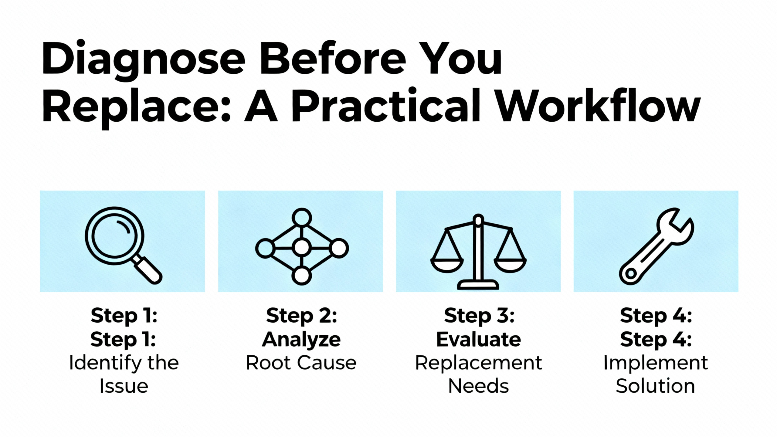
Diagnose Before You Replace: A Practical Workflow
Jumping straight to probe replacement is tempting when a turbine is on hold and vibration channels are screaming. It is also the fastest way to waste parts and time. A more disciplined approach, drawn from Instrumentation and Control Engineering, Amikong, The Modal Shop, and OMCHŌĆÖs general proximity sensor testing guidance, is safer and faster in the long run.
Start With Safety And System Context
Before touching probes or cables, put the machine in a safe state. The OMCH industrial testing guide stresses proper lockŌĆæout and tagŌĆæout so that shaft movement does not restart unexpectedly while you are working at the bearing housings. In a power plant environment, tie this into your normal workŌĆæpermit process so that turbine supervisory instrumentation and machine protection teams are aligned.
Next, capture context from the monitoring system. On Bently Nevada 3500 racks, look at the channel OK status, alert and danger status, and any event logs. Determine whether the channel is in a ŌĆ£Not OKŌĆØ condition, bypassed, or simply in alarm. Note when the problem started relative to machine startups, process changes, or recent maintenance.
Check Gap Voltage And Power At The Monitor
The fastest electrical indicator of measurement health is the DC gap voltage. This can be read at the module front panel or buffered output BNC on a Bently Nevada monitor. Amikong explains that for a healthy probe, you should see a stable negative DC value near the configured gap target, often around negative ten volts for many installations. At standstill, there should be almost no AC riding on this DC level.
If the reading is driven close to the negative supply rail, in the negative twentyŌĆæplus volt region, that often indicates an open loop, such as a disconnected cable or broken conductor. If it is near zero volts, it may indicate a short. Power to the Proximitor itself, typically on the order of negative eighteen to negative twentyŌĆæfour volts DC, should also be verified at its terminals or power feed.
A stable, reasonable gap voltage with bad vibration does not point to a dead probe. It pushes you toward mechanical, configuration, or process causes instead.
Perform A Careful Visual Inspection And Wiggle Test
Field failures summarized by Amikong highlight how often the evidence is visible. Walk the entire accessible probe and extension cable route. Look for cuts, abrasions, tight bends, crushed sections, or any sign that the cable has been used as a handle during other maintenance. Inspect the probe tip for signs of rubbing, impact, or metal transfer.
Reseat all connectors, including any ClickLoc connectors in Bently Nevada transducer systems. Loose or partially engaged connectors cause intermittent faults and spuriously changing readings. Ensure connectors are clean and dry; contamination by oil, moisture, or dirt is a recurring theme in failure reports.
While watching the monitor, gently move suspect cable sections and connectors. The ŌĆ£wiggle testŌĆØ that Amikong recommends is extremely effective. If a small movement of the cable causes the reading to jump, drop out, or suddenly become stable, you have likely found a weak or cracked section of the cable or a bad connector. That strongly suggests a cabling issue rather than a failed probe coil.
Verify Cable Integrity And Resistance
When the visual checks suggest a damaged loop, bring in the multimeter. Instrumentation and Control Engineering provides typical resistance ranges for Bently Nevada probes and extension cables: about five to nine ohms for the probe and roughly five to twenty ohms for the extension cable, depending on length and model. Amikong repeats similar values for common 8 mm probes.
Disconnect the probe and cable from the Proximitor and from each other as needed. Measure resistance across the center conductor and shield at each segment. An open circuit (infinite resistance) indicates a break. A nearŌĆæzero reading between the inner conductor and shield indicates a short. Values far outside the expected band suggest a component or connection that is no longer within specification.
The Modal Shop stresses that cabling errors, not probe electronics, are the leading cause of proximity system failures. That includes incorrect cable lengths or mismatched cable families, not just physically damaged cable. Compare measured lengths and part numbers to your asset records.
Confirm Component Matching And System Design
Several sources, including Baker Hughes, Amikong, and The Modal Shop, warn against mixing manufacturers or random parts across systems. A Bently Nevada proximity transducer system assumes a specific probe type, a specific extension cable type and length, and a specific driver model and calibration. Using thirdŌĆæparty probes or cables to save money or lead time converts the loop into a ŌĆ£Frankenstein systemŌĆØ with unknown calibration and degraded reliability.
Check your parts list against the original design or OEM recommendations. Confirm that probe, cable, and Proximitor part numbers all belong to the same family and total design length. UbestŌĆÖs wiring guide also reminds you to use genuine, shielded coaxial cables with the correct fiftyŌĆæohm impedance. Generic coax that fits physically can introduce measurement errors and noise.
If a probe was recently replaced and the problem began immediately afterward, mismatched parts or incorrect gap setting are more likely than simultaneous probe failure.
Use A Static Functional Test When Possible
If you can safely remove the probe or work on a spare in the shop, the functional test procedure described by Instrumentation and Control Engineering is extremely useful. Mount the probe in a calibrated micrometer fixture with a conductive target plate. Connect it to a matching Proximitor and power supply. Then:
Set the micrometer so the target is at a zero reference point near the probe tip and record the negative DC output voltage.
Increase the gap in small increments, such as ten mils at a time, out to around eighty or ninety mils. At each step, record the output.
Plot voltage versus gap. Over the central range, roughly ten to eighty mils, the plot should be a straight line. The articleŌĆÖs worked example shows a neat progression where voltage increases linearly by about one and a half volts every ten mils, corresponding to a sensitivity of about two hundred millivolts per mil.
If your curve shows obvious curvature or flattening inside that central band, or large irregular jumps, the probe may be out of calibration or damaged. If instead it is linear and close to the expected slope, the probe and driver are functioning and your problem lies elsewhere.
This type of functional test is also an excellent baseline tool. Baker Hughes and The Modal Shop recommend regular static and dynamic calibration checks as part of maintaining probe system reliability.
Decide: Replace The Probe Or Fix The System?
At this point, you have several pieces of evidence: rack status and gap voltage, visual inspection results, wiggle test behavior, resistance measurements, component matching checks, and possibly a static functional test. Only when you have a consistent story that points to the probe itself should you move to replacement.
The typical decision path looks like this. If gap voltage is at a supply rail, resistance checks show an open or short in the probe itself, and static tests show nonŌĆælinear behavior, you have a strong case for probe failure. If resistance checks and static tests are good but cabling is suspect, focus on replacing or reŌĆærouting cable and cleaning connectors. If a 3300 NSv probe shows zero output but the loop tests and driver checks are good, investigate configuration and target geometry before condemning the sensor.
In every scenario, the principle is the same: treat the probe as one component in a calibrated chain and prove it is the bad actor before you swap it.
Choosing The Right Replacement Proximity Probe
Once you are confident the probe must be replaced, selection is not simply a matter of matching thread and tip diameter. The research from Baker Hughes, Amikong, The Modal Shop, and cable suppliers such as NexAuto highlights several points.
First, keep the system matched. Use a probe, extension cable, and Proximitor from the same OEM, in the same product family, and with the same design length as the original. This maintains the calibrated transfer function and linear range. For critical machinery protection, sticking with a fully matched Bently Nevada chain is strongly recommended. Aftermarket or thirdŌĆæparty probes might appear compatible but can change sensitivity, linear range, and temperature behavior.
Second, match cable length and type. NexAutoŌĆÖs discussion of the 330730 series extension cables emphasizes that length and connector type are encoded in the part number. Using a cable of different length or a nonŌĆæshielded substitute affects signal quality and calibration. UbestŌĆÖs guidance calls out the need for a fiftyŌĆæohm coaxial cable designed for dynamic measurements and for careful inspection of connectors before installation.
Third, consider environmental conditions. NexAuto notes that popular Bently Nevada extension cables are designed for harsh environments, with operating temperature ranges roughly from about negative sixty degrees Fahrenheit up to about three hundred fifty degrees Fahrenheit and robust shielding against electromagnetic interference. In hot turbine enclosures or near steam piping, this range can be used up quickly, so choose parts rated for your worstŌĆæcase temperature and contamination conditions.
Fourth, avoid mixing OEM and nonŌĆæOEM components within a single loop. Baker HughesŌĆÖ reliability literature points out that modern proximity systems are designed for long life, with mean time between failures commonly in the hundreds of thousands of hours when installed and maintained correctly. Deliberately breaking the calibration by mixing components defeats that engineering effort and makes downstream data hard to trust.
When in doubt, consult your machineŌĆÖs original Bently Nevada transducer system datasheet rather than generic catalog pages. That is your blueprint for a replacement that preserves both protection and data quality.
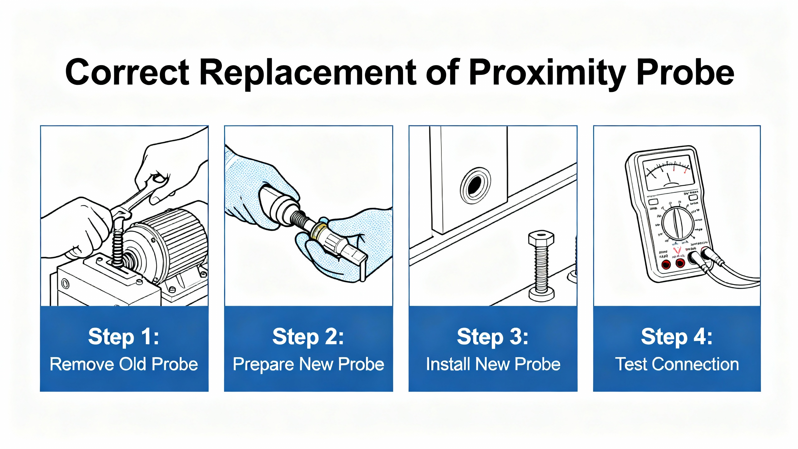
How To Replace A Bently Nevada Proximity Probe Correctly
Replacing a proximity probe is not complicated, but doing it casually is where many ŌĆ£mystery vibrationŌĆØ problems begin. The steps below align with best practices from Ubest, The Modal Shop, and Amikong, adapted for a power and protection context.
Isolate, Document, And Prepare
After applying lockŌĆæout and tagŌĆæout on the machine, document baseline information. Record current gap voltage and vibration trend behavior, even if it is faulty. Capture monitor configuration screenshots or printouts. Take photos of the existing probe mounting, cable routing, and connector terminations. These reference points are invaluable if something later looks wrong.
Gather the new probe, matching extension cable, and any new Proximitor if the driver is also being replaced. Verify part numbers and lengths against the design documents before you open anything in the field.
Remove The Old Probe And Cable Without Adding Damage
Access the probe location at the bearing or turbine casing. Loosen the mounting hardware carefully without twisting the cable excessively. Withdraw the probe straight out as much as possible to avoid scraping the tip along the shaft or bore.
Trace the extension cable route back to the Proximitor or rack. Release cable clamps and supports as you go, and disconnect connectors without pulling on the cable jacket. This is the time to look for hidden damage: crushed spots under clamps, tight bend radii at bulkhead penetrations, or sections that have rubbed on sharp metal edges.
Once removed, tag the old probe and cable with the machine location and channel identifier. If your organization has access to a static test bench as described by Instrumentation and Control Engineering, you can later test this removed chain to confirm your failure diagnosis and improve your plantŌĆÖs failure statistics.
Install The New Probe And Extension Cable With Good Wiring Practices
Route the new extension cable following or improving the original path. UbestŌĆÖs wiring guide for the 3300 XL 8 mm probe stresses several points that are broadly applicable.
Use shielded fiftyŌĆæohm coaxial cable designed for dynamic measurements, not generic coax. Avoid running probe cables in the same conduit as highŌĆævoltage or highŌĆæcurrent power lines. Keep at least about one foot of physical separation from AC power cables and motor leads to minimize electromagnetic interference. Where crossings are unavoidable, cross at right angles and keep the contact length as short as practical.
Secure the cable with clamps or supports so that it cannot vibrate against sharp edges or hang from the probe or connector body. Leave generous bend radius at junction boxes or penetration points to prevent longŌĆæterm mechanical fatigue.
Follow a singleŌĆæpoint grounding strategy. Ground the cable shield at the monitor or Proximitor end only, as Ubest notes, and avoid grounding the probe body or cable shield at the sensor end. This reduces ground loops that can otherwise cause erratic readings in sensitive lowŌĆævoltage signals.
Make terminations at the monitor or driver carefully. Strip insulation with appropriate tools, avoid nicking the inner conductors, and keep terminations clean and dry. Tighten terminal screws firmly and reŌĆæcheck them after a short period, since soft copper can relax.
Set The Initial Gap Using Gap Voltage
With the new chain connected and the machine still at rest, apply power to the Proximitor and monitoring rack. Monitor the DC gap voltage at the channel. Adjust probe insertion depth slowly while watching this reading. Amikong and Baker Hughes explain that the target is to place the shaft in the middle of the probeŌĆÖs linear range, which for many Bently Nevada systems corresponds to a gap voltage in the neighborhood of negative ten volts.
Consult the specific datasheet for your probe family and driver to confirm the recommended gap voltage range. As you adjust, ensure that the probe mounting remains mechanically secure, with no risk of loosening into the shaft path under vibration.
Once the desired gap is achieved, tighten the probeŌĆÖs mounting hardware to the specified torque. ReŌĆæcheck gap voltage after tightening; heavyŌĆæhanded tightening can sometimes shift the gap slightly.
Verify Functionality With Static And Dynamic Checks
Before returning the machine to service, verify that the loop behaves as expected. At standstill, confirm that gap voltage is stable and within the recommended band and that the monitor indicates an OK status without alarms or ŌĆ£Not OKŌĆØ indications. Gently move cable sections to ensure that the reading does not flicker, which would indicate a wiring or connector weakness.
If you have access to a portable vibration calibrator such as the shaker described by The Modal Shop, perform a dynamic check. These devices can generate a controlled shaftŌĆælike motion to confirm the sensitivity of the probe loop and verify alert and trip thresholds in the protection system. The Modal Shop notes that combining static calibration against a steel target with dynamic checks at realistic running speeds provides a high degree of confidence in the systemŌĆÖs performance.
Finally, document the new baseline. Record the new probe and cable part numbers, measured gap voltage, and any calibration results. Trend these values over time; slow drift in gap voltage or increased noise levels can be early signs of future problems.
Preventing Future Proximity Probe Failures
Fixing a failed probe is one thing. Reducing the rate at which you see failures is where reliability gains show up in power system availability and maintenance budgets.
Several patterns emerge across sensor and vibration literature from Baker Hughes, The Modal Shop, CNLanbao, Disruptive Technologies, and others.
Installation quality is foundational. UbestŌĆÖs wiring best practices and The Modal ShopŌĆÖs cabling error notes both stress that correct cable selection, routing, and grounding are not optional refinement. They directly determine whether the probe system operates within its calibrated range or spends its life fighting noise, ground loops, and intermittent opens. Most ŌĆ£mysteriousŌĆØ vibration channel problems I have seen on generator or turbine trains trace back to shortcuts taken in cable routing during a rushed outage.
Environment matters. CNLanbao cites studies suggesting that a large fraction of factory sensor failures are environmental: temperature extremes, dust, moisture, and electromagnetic interference. Disruptive Technologies describes how condensation, strong magnetism, and mechanical impact can permanently damage sensors. For Bently Nevada probes, that means shielding probes from direct fluid impingement where possible, using FluidLocŌĆæstyle designs where appropriate, and avoiding routing cables through zones where they can be crushed, stepped on, or bathed in oil.
Regular functional checks pay off. Baker HughesŌĆÖ reliability perspective notes that proximity systems, when installed and maintained correctly, are designed for long life with mean time between failures in the hundreds of thousands of hours. Achieving that requires maintenance routines. Periodic gap voltage checks, static functional tests on spare chains, and occasional dynamic checks with a portable calibrator can separate true machine changes from sensor or wiring degradation.
Configuration discipline is often overlooked. As seen in temperature monitoring on Bently Nevada 3500 racks, misconfigured input types, lead compensation, or setpoints can create false alarms and erode operator trust. The same is true for vibration. Ensure that channel configuration matches the installed probe family and scale factor. When upgrades or replacements are made, follow change control so that engineering, operations, and maintenance share a single truth about what is installed.
Finally, stock and labeling are cheap insurance. Keeping a small inventory of correctly matched probes, cables, and drivers reduces the temptation to substitute ŌĆ£almost rightŌĆØ parts in a rush. Labeling each probe and cable set with its intended channel and total length makes it much harder to crossŌĆæmix components into unreliable combinations.
In a powerŌĆæsystem context, these measures translate directly into more stable operation of turbines, generator sets, motor loads, and the UPS and inverter systems that depend on them.
Short FAQ
How do I know the probe itself is bad, not just the cabling?
Look for consistency across tests. If gap voltage is pinned at a supply rail, resistance measurements show an open or short at the probe, and a static micrometer test shows nonŌĆælinear behavior inside the normal gap range, the probe is suspect. If the probe passes a shop functional test but vibration remains abnormal, focus on cabling, connectors, and configuration instead.
Is it ever acceptable to mix thirdŌĆæparty probes with Bently Nevada drivers?
For machinery protection on highŌĆævalue assets, the consensus from Baker Hughes, Amikong, and The Modal Shop is no. Mixing components breaks the calibrated transducer chain and introduces unknown measurement errors. For nonŌĆæcritical condition monitoring applications, some plants do experiment, but they do so with full awareness that protection reliability is reduced. For turbines, compressors, and generator trains tied to power systems, sticking with OEMŌĆæmatched sets is the safer choice.
How often should I perform functional checks on proximity probes?
At minimum, check gap voltage and channel OK status during every major outage or after any maintenance that touches probes or cabling. Many reliability programs add a deeper static functional test on spare chains annually and dynamic calibration checks on critical machines every few years, in line with protection standards guidance. The key is consistency: trending the same measurements over time is more valuable than performing an elaborate test only once.
Maintaining the health of your Bently Nevada proximity probes is not about chasing sensor failures. It is about preserving a calibrated protection chain that stands between your rotating assets and costly downtime. Diagnose carefully, replace intelligently, and your power system will thank you with quiet, predictable operation.
References
- https://rotorlab.tamu.edu/me459/sensors/2009%20Orbiz%20on%20Prox_Probes.pdf
- http://turbolab.hanyang.ac.kr/Probe%20installation%20tips.pdf
- https://www.apterplc.com/a-comprehensive-guide-to-the-bentley-nevada-proximity-sensor-system_n104
- https://www.amikong.com/n/proximity-probe-diagnosis-replacement-guide
- https://automationforum.co/functional-testing-of-bently-nevada-vibration-probes/
- https://www.bxuansensor.com/blog/troubleshooting-common-proximity-switch-issues-and-fixes
- https://www.omch.com/proximity-sensor-test/
- https://www.powergearx.com/avoid-costly-downtime-a-guide-to-3300-xl-8-mm-proximity-probe-failure-modes/
- https://www.bakerhughes.com/bently-nevada/blog/vibration-and-dynamic-measurements
- https://www.cascadeindustrial.com/blogs/resource-center/troubleshooting-guide-for-proximity-sensor?srsltid=AfmBOoqv93qw9hqIzvn4PyQIjQ9I67Gcw-EM_WmoFbxneW4yFiPwEdSn


 Videos
 News
News Applications


Leave Your Comment