Why A ŌĆ£SimpleŌĆØ Probe Failure Becomes A Power-Reliability Problem
When you run powerŌĆæcritical assetsŌĆömotors on large UPS systems, compressor trains feeding process air to switchgear rooms, turbines driving generatorsŌĆöa Bently Nevada proximity probe that stops working is not just an instrumentation annoyance. It is a loss of primary protection on a machine whose failure can cascade into trips, black starts, and very expensive downtime.
In machinery audits and incident reviews, I repeatedly see the same pattern. A single radial probe or Keyphasor goes ŌĆ£Not OK,ŌĆØ alarms are bypassed ŌĆ£temporarily,ŌĆØ and a few weeks later the plant is asking why a bearing failure or rotor rub was not caught earlier. The vibration system did not fail mysteriously; the probe loop failed in a very predictable way.
In this article I will walk through how a Bently Nevada eddyŌĆæcurrent proximity probe system actually works, what ŌĆ£not workingŌĆØ usually means in the field, the main technical root causes, and a practical troubleshooting and prevention approach grounded in real OEM guidance and field cases. The focus is on Bently Nevada systems used on critical rotating machinery that underpins industrial and commercial power reliability.
How A Bently Nevada Proximity Probe System Really Works
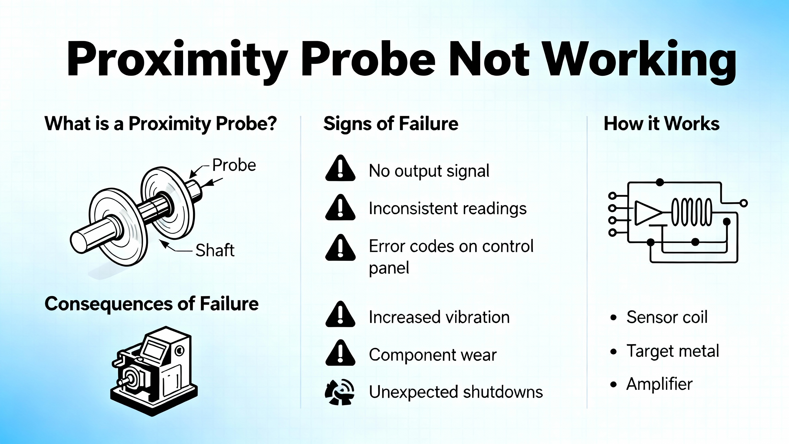
A Bently Nevada proximity probe is not a single component. It is a calibrated measurement system built around eddyŌĆæcurrent technology, engineered as a matched set.
From the diagnostic and maintenance guides published by Amikong and Baker Hughes Bently Nevada, the system consists of three tightly coupled elements: the probe, the extension cable, and the proximitor (often called a driver). These are designed, manufactured, and calibrated as a single transducer system. If you change one element arbitrarily, the calibration and linearity can no longer be trusted.
EddyŌĆæcurrent probes operate by energizing a small coil in the probe tip with a highŌĆæfrequency signal from the proximitor. When a conductive shaft sits in front of the probe, eddy currents are induced in the shaft surface. Those eddy currents draw energy from the probeŌĆÖs electromagnetic field. The proximitor measures this energy loss and converts it into a voltage.
That voltage has two components, as described in AmikongŌĆÖs proximity probe guide. First there is the negative DC gap voltage that represents the average probeŌĆætoŌĆæshaft distance. It is typically set near a nominal value such as about minus ten volts during commissioning. Then the shaft vibration appears as a small AC signal superimposed on that DC level. As the shaft moves closer and farther from the probe, the voltage swings around the average value.
Bently Nevada 3500ŌĆæseries monitors, and modules such as the 3500/42M, continuously watch that signal. They use frontŌĆæpanel LEDs and internal diagnostics to flag when a channel is no longer trustworthy. A ŌĆ£Not OKŌĆØ status indicates an invalid measurement loop, for example an open or shorted circuit or a gap voltage outside the calibrated linear range. In that state, the protection logic for that channel is automatically bypassed to avoid false shutdowns. In practice, this also means you have lost real protection for that point.
On the same machines you will often find a Bently Nevada Keyphasor. This is a onceŌĆæperŌĆærevolution reference pulse that provides rotational speed and phase information. Without a healthy Keyphasor, advanced vibration analysis and many predictive analytics become blind. A case reported on an Automation & Control Engineering Forum for a Demag compressor showed how loss of the Keyphasor signal after startup, combined with abnormal radial probe readings, drove operators into repeated troubleshooting and component replacements before normal behavior was restored.
Understanding this architecture is essential: probe health is not a cosmetic detail. It is the front end of your mechanical protection and a critical input to your plantŌĆæwide condition monitoring and power reliability strategy.
| Component | Role in the system | Typical failure symptoms |
| Probe | Senses shaft position and vibration via eddyŌĆæcurrent field | Rubbed or bent tip, erratic signal when cable is moved |
| Extension cable | Carries highŌĆæfrequency signal between probe and proximitor | Intermittent readings, sensitivity to cable movement |
| Proximitor | Powers probe, demodulates signal, outputs DC gap + AC vibration | Extreme voltages, frozen reading, ŌĆ£Not OKŌĆØ on monitor |
| Monitor module | Interprets signals, applies alarms/trips, provides diagnostics | ŌĆ£Not OK,ŌĆØ bypassed channel, LED fault states |
| Keyphasor | OnceŌĆæperŌĆærev reference for speed and phase | Loss of speed/phase, analytics and plots become unreliable |

What ŌĆ£Proximity Probe Not WorkingŌĆØ Means In Practice
When maintenance or operations says ŌĆ£the Bently Nevada probe is not working,ŌĆØ their observation usually falls into a few concrete categories that are well documented in Bently Nevada and InstrumentationTools troubleshooting guides, and in field experience.
One common scenario is a clear ŌĆ£Not OKŌĆØ indication on a monitor channel. In this case the module may drive the reading to an extreme value, such as close to the negative powerŌĆæsupply rail for an open circuit or near zero volts for a short circuit, and then mark the channel as not trustworthy. On a 3500/42M module, a fastŌĆæflashing or dark OK LED combined with an active Bypass LED is often associated with this condition, and the channelŌĆÖs alarms are automatically disabled.
Another pattern is erratic or spiking readings. The vibration amplitude may jump rapidly even though speed, load, and sound from the machine remain steady. Amikong and InstrumentationTools both highlight that such behavior often points to a loose connector, damaged cable, or a poor gap setting. The same effect can be produced intentionally during a wiggle test, where you gently move the cable and observe if the reading changes with cable movement.
A third symptom is a frozen signal. The machine changes operating state, but one probeŌĆÖs reading stays perfectly flat or pegged at a constant value. That can indicate a failed proximitor, a probe loop that has fallen outside its linear range, or, in some cases, a channel that has been inadvertently bypassed or misconfigured.
Finally, there are cases where the proximity probes may appear normal, but the Keyphasor fails, as in the Demag compressor forum case. Without the phase reference, orbit plots and many advanced diagnostics become unusable even if absolute vibration amplitudes still look reasonable. This subtle form of ŌĆ£not workingŌĆØ is often recognized only when an analyst tries to perform detailed vibration analysis and finds that phaseŌĆærelated plots are missing or nonsensical.
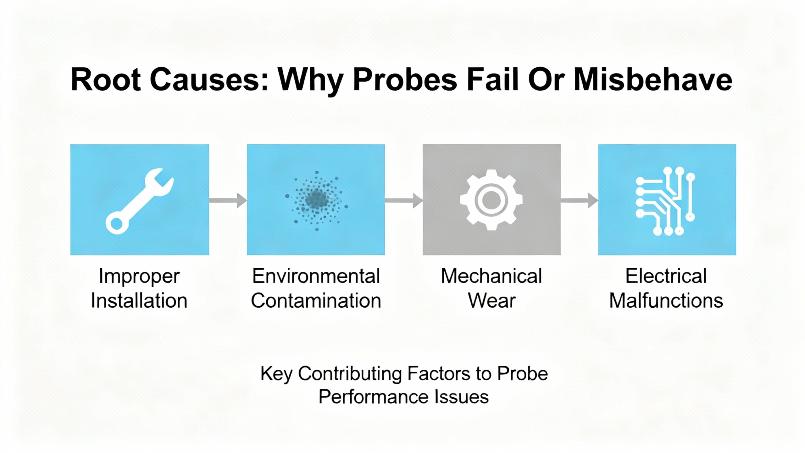
Root Causes: Why Bently Nevada Probes Fail Or Misbehave
The good news is that proximity probe failures are rarely random. Across OEM guidance and field reports, several recurring technical causes stand out.
Physical Damage And Contamination
In the Amikong field guide, physical damage is cited as the most frequent cause of proximity probe failure. On real equipment I regularly find: crushed or sharply bent probe cables where electricians stepped on conduit; rubbed or broken probe tips after a rotorŌĆætoŌĆæprobe contact; and cables abraded where they pass through tight gland holes.
Connector contamination is another chronic offender. Oil, moisture, and dirt inside connectors degrade signal quality. Some Bently Nevada cables include a FluidLoc feature designed to stop fluid wicking along the cable. Even so, once contamination reaches the connector the result can be intermittent readings and ŌĆ£Not OKŌĆØ states.
On smartphones and small devices, OMCHŌĆÖs sensor troubleshooting guide highlights how simple dirt and facial oils over the sensor window can completely confuse a proximity sensor. The same principle applies in industry: layers of oil mist, dust, or process residue on probe bodies, junction boxes, and terminal strips mimic or hide mechanical motion.
Wiring And Cabling Errors
The Modal ShopŌĆÖs troubleshooting guidance is blunt: cabling is the leading cause of failures in eddyŌĆæcurrent probe systems. Proximitor performance depends on using the correct cable type and length because the cableŌĆÖs electrical characteristics are part of the calibration. When a different length or an incorrect coaxial cable is used, the dynamic output can become too high or too low, resulting in false trips or dangerously delayed trips.
Wiring practices matter as much as cable part numbers. Ubest AutomationŌĆÖs wiring recommendations for the Bently Nevada 3300 XL 8 mm probe emphasize several best practices: use genuine shielded coaxial extension cables with the proper impedance, route probe cables away from power lines and motor leads, maintain physical separation from highŌĆævoltage wiring, clamp cables so vibration does not transfer into connectors, and use a singleŌĆæpoint grounding scheme where the shield is grounded at the monitor end only. Ignoring any of these points invites electromagnetic interference, ground loops, and intermittent behavior that is very hard to diagnose later.
In plant walkdowns it is common to see proximity probe cables sharing trays with motor feeders, shield connections made at both ends, and adŌĆæhoc splices wrapped in generalŌĆæpurpose tape. Every one of those shortcuts is directly at odds with the OEM guidance and with the experience summarized by The Modal Shop and Ubest.
Installation And Gap Errors
Proximity probes must operate within a defined mechanical and electrical gap window for their output to be linear. InstrumentationToolsŌĆÖ stepŌĆæbyŌĆæstep troubleshooting guide for vibration probes underlines the importance of verifying gap voltage and mechanical gap when symptoms appear.
If the initial gap setting was wrong, the probe can operate near the edge of its linear range, causing either artificially low or high vibration readings. The guide recommends verifying the DC gap voltage, typically set around a machineŌĆæspecific value such as minus seven and a half or minus ten volts, and observing it for stability over ten to fifteen seconds. Tapping the cable or probe while watching that voltage is a simple way to expose marginal connections or internal damage.
Installation crosstalk is another subtle issue. When two probes are mounted too close together, their electromagnetic fields can interfere, creating corrupted readings on both channels. OEMs provide minimum separation distances for this reason. The Amikong material also warns against the use of general Teflon tape at the probeŌĆōextension junction, recommending instead the specially supplied insulation tape. The wrong tape can worsen noise performance rather than improve it.
Environmental And PowerŌĆæSupply Factors
Proximity sensors in general are sensitive to temperature, humidity, and electromagnetic noise. Disruptive TechnologiesŌĆÖ proximity sensor troubleshooting guide, although aimed at a different class of sensor, illustrates how operating outside the specified temperature range or leaving sensors in condensing environments for long periods can shorten lifespan or cause permanent damage.
OMCH, Cascade Industrial, and Haas CNC troubleshooting notes all stress the basic but critical rule of verifying that sensors receive their correct supply voltage before blaming them for misbehavior. Many industrial proximity sensors are designed for DC supplies in a specified range, for example around ten to thirty volts. If the supply falls below the minimum, sensors may behave erratically or go offline completely. The strategy applies directly to Bently Nevada systems as well: check that the proximitor and monitor modules receive their specified power and that any UPS or inverter feeding the rack is stable and correctly coordinated.
Electromagnetic interference from nearby motors, variableŌĆæfrequency drives, radio systems, or poorly grounded equipment can induce noise on probe cables. Disruptive TechnologiesŌĆÖ guidance on connectivity issues and EMI points to motors, fluorescent lighting, and other transmitters as common culprits. In the context of Bently Nevada probes, that interference shows up as noisy signals, false vibration spikes, or channels that toggle between OK and Not OK without any real mechanical change.
Mixing OEM And ThirdŌĆæParty Components: The ŌĆ£Frankenstein SystemŌĆØ
One of the most serious and often overlooked causes of proximity probe malfunction is mixing components from different manufacturers. Baker Hughes Bently Nevada has written extensively about this, popularizing the term ŌĆ£Frankenstein system.ŌĆØ
Amikong and Bently Nevada both reiterate that the probe, extension cable, and proximitor are engineered as a single calibrated unit. When plants swap in thirdŌĆæparty ŌĆ£compatibleŌĆØ drivers or probes while keeping the rest of the loop unchanged, the transfer function of the system changes in ways that are not visible during a quick startup check.
Baker Hughes presents test data showing that in a nineŌĆæmeter mixed system, vibration readings can be attenuated by about a quarter at certain gaps. A displayed six mil peakŌĆætoŌĆæpeak vibration might correspond to an actual vibration level above eight mil peakŌĆætoŌĆæpeak. In shorter fiveŌĆæmeter mixed systems, readings can be exaggerated instead. In both cases, alarm and trip setpoints that were carefully agreed upon through a formal Management of Change process are silently altered by the component swap, without any change to the configured numbers.
No manufacturer is willing to warrant such mixed systems. Beyond nuisance trips and production losses, the real danger is underŌĆæreporting of thrust or radial vibration on critical turbomachinery, which can lead to catastrophic failures before any alarm is raised.
SystemŌĆæSide Issues: Monitor Modules And Analytics
Sometimes the probe is blamed for issues rooted in the monitoring system itself. AmikongŌĆÖs descriptions of the 3500/42M moduleŌĆÖs LED behavior make it clear that an unlit TX/RX LED can indicate a failed module that is not communicating, while a fastŌĆæflashing OK LED can indicate either an internal fault or a Not OK transducer loop.
Bently NevadaŌĆÖs Decision Support analytics, described by Baker Hughes, are designed to use highŌĆæresolution System 1 data and prebuilt or custom rules to detect not only mechanical faults but also instrumentation problems. For example, a rule might flag a sudden loss of Keyphasor events, frozen vibration magnitude with changing process conditions, or persistent Not OK states as instrumentation issues needing attention. If those analytic outputs are ignored, the plant effectively continues operating with partial protection even though the software has already identified a sensor health issue.
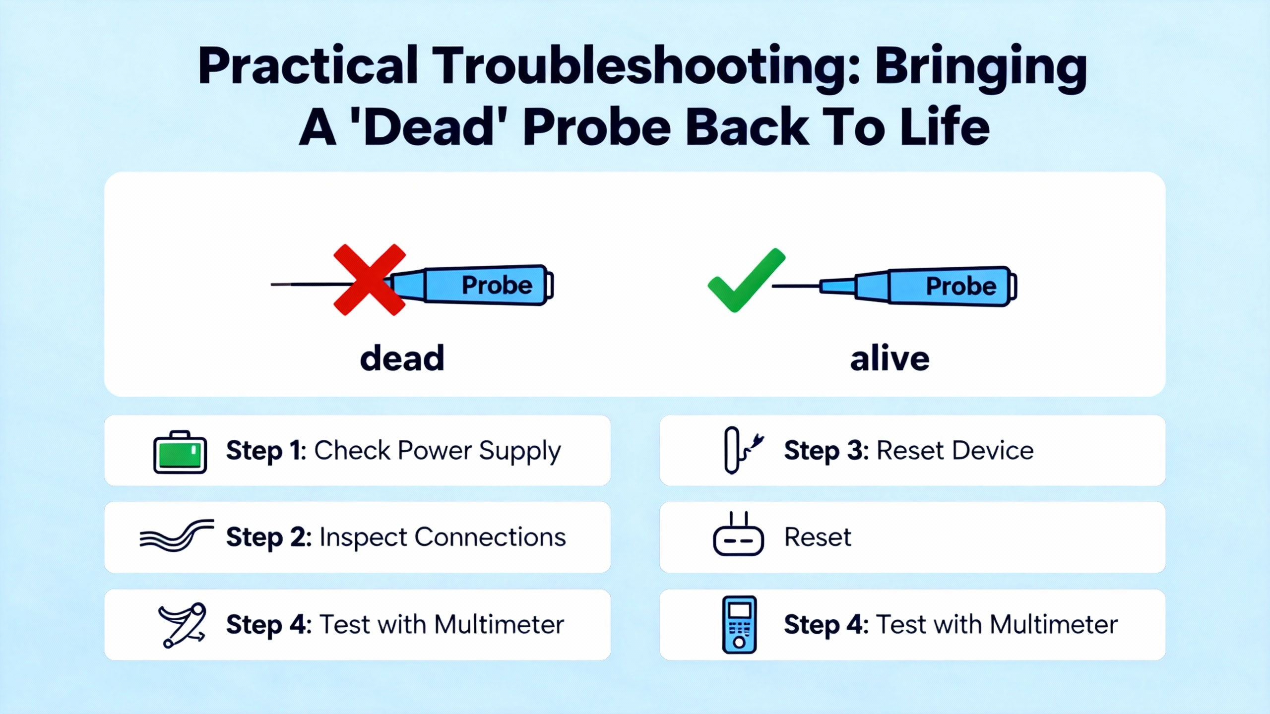
Practical Troubleshooting: Bringing A ŌĆ£DeadŌĆØ Probe Back To Life
When a Bently Nevada proximity probe appears not to be working, the fastest path to a safe solution is a structured approach. The following workflow consolidates the concrete recommendations from InstrumentationTools, Amikong, The Modal Shop, Ubest, and other proximityŌĆæsensor troubleshooting guides, adapted to the realities of powerŌĆæcritical plants.
Start With Safety And Context
Before touching any wiring, verify that the machine is in a safe state. Cascade IndustrialŌĆÖs proximity sensor guide recommends placing equipment in an emergencyŌĆæstop condition before testing sensors, to avoid unexpected motion. In larger plants, that often means following formal lockout/tagout procedures and coordinating with both electrical and mechanical teams, especially if machines supply essential power, compressed air, or cooling to UPS rooms and switchgear.
At the same time, gather context from the monitoring system. On a Bently Nevada 3500 rack, note which channels are in Not OK, which LEDs are lit or flashing on modules, and whether Keyphasor inputs are healthy. In systems with Decision Support analytics, review any active sensorŌĆæhealth or instrumentation rules before heading to the field.
Visual Inspection And The ŌĆ£Wiggle TestŌĆØ
Next, perform a methodical visual inspection, starting from the monitoring rack and working toward the probe. Amikong and InstrumentationTools both emphasize tracing the entire visible cable path and checking for cuts, abrasions, overly tight bends, and any points where cables have been crushed or pinched.
At each connector, including junction boxes and the probeŌĆōextension joint, disconnect and visually inspect the pins and sockets. Look for oil, moisture, dirt, or corrosion. Clean as appropriate according to OEM procedures, reconnect firmly, and make sure Bently Nevada ClickLoc connectors are fingerŌĆætightened until they audibly click into place.
While a channel is being observed on the monitor or on its buffered output, gently move the cable near each connector and at typical stress points. This wiggle test, highlighted in the Amikong guide, is remarkably effective. If the reading jumps, drops out, or suddenly stabilizes as the cable is moved, you have located a likely internal break or poor connection.
Inspect the probe tip itself when accessible. A probe that has contacted the shaft may show a polished spot, deformation, or complete breakage. Any such damage is grounds for replacement and for a separate mechanical rootŌĆæcause analysis of why the contact occurred.
Check Gap Voltage And Stability
With the probe installed, monitor its DC gap voltage, preferably using the buffered output on the front of the monitor module. InstrumentationTools recommends watching the gap voltage for ten to fifteen seconds under steady operating conditions. It should sit near the intended setpoint and remain stable.
If the DC voltage is near the negative supply rail or close to zero under conditions where it should be in its linear zone, the probe loop is out of range or open or shorted. If the voltage flickers or jumps significantly when the cable or probe is gently tapped, that again points to a weak connection or damaged component.
The key is to distinguish between a genuine mechanical event (which should also be apparent in other probes and in machine sound, process parameters, or bearing temperatures) and a loop issue confined to one probe. Stable process conditions plus unstable gap voltage almost always indicate a transducer problem.
Electrical Checks With A Multimeter
For personnel comfortable with electrical testing, Amikong describes simple but powerful multimeter checks. One is to measure the buffered output voltage for each channel. A healthy proximity loop should show a steady negative DC voltage around the intended operating point. An absent voltage, a reading pinned at the full supply voltage, or an unstable voltage confirms a fault in the transducer loop.
Another check involves measuring the DC resistance of the probe and extension cable after they have been disconnected. The manufacturerŌĆÖs documentation provides the expected resistance values; as one example cited, a typical eightŌĆæmillimeter probe might show between about five and nine ohms of resistance. An infinite resistance indicates an open circuit, while zero ohms between the center conductor and shield indicates a short.
For other proximity sensors in the plant, OMCH, Cascade Industrial, and Haas CNC guides all highlight the same discipline: never assume a sensor is bad until the supply voltage at the terminals has been verified with a meter and the basic signal behavior is understood. The principle carries over to Bently Nevada proximitor power supplies and rack power: confirm that what the manuals specify is actually being delivered.
Isolate The Faulty Component
When basic checks indicate a transducer problem but do not isolate which component is bad, InstrumentationTools recommends a simple but rigorous substitution method using knownŌĆægood spares.
First, test the existing probe with a new extension cable and proximitor. If the system behavior returns to normal, the extension or proximitor is suspect. If not, swap just the probe, using the new probe with the existing extension and proximitor. Finally, test the existing proximitor with the new probe and extension.
At each stage, perform a linearity check, often using a micrometer to move a steel target in front of the probe over its specified displacement range, and verify the output voltage remains linear. The defective component will typically reveal itself through a nonŌĆælinear response or inability to hold a stable gap voltage.
The Modal Shop further recommends verifying alert and alarm trip points under realistic dynamic conditions using a portable vibration calibrator, so that both calibration and protection logic are proven together before the machine returns to service.
Verify Cabling, Length, And Wiring Practice
Once a component has been repaired or replaced, confirm that the extension cable length and type match the original design. As The Modal Shop notes, using cables of incorrect length or impedance changes the proximitorŌĆÖs dynamic output and can make the system read high or low.
Follow UbestŌĆÖs wiring practices carefully when reinstalling: keep coaxial cables away from power conductors, maintain clean terminations at the monitor, connect cable shields to ground at the monitor end only, and ensure all terminal screws are tight and free of contamination. Then repeat gapŌĆævoltage checks and basic vibration measurements to confirm the system behaves as expected over the operating range.
Confirm System Configuration And Analytics
Finally, check the monitoring software configuration. On a 3500/42M, an OK LED flashing slowly can indicate an unconfigured module, and a lit Bypass LED means alarms are disabled. The Amikong LED status table advises consulting the System Event List in the monitoring software to see precisely why a channel is Not OK or bypassed.
If your plant uses Bently NevadaŌĆÖs System 1 with Decision Support analytics, review any instrumentationŌĆærelated rules tied to that probe. In one of Baker HughesŌĆÖ case studies on a recycle gas compressor, a custom algorithm watched not only orbit shape and vibration magnitude but also the rate of change on a particularly sensitive probe pair to give earlier, machineŌĆæspecific warnings. The same framework can be used to catch sensor failures early by monitoring for frozen traces, missing Keyphasor pulses, or persistent Not OK states.
Preventing Repeat Failures In PowerŌĆæCritical Plants
Treating probe faults as oneŌĆæoff nuisances is a recipe for repeated loss of protection. Reliable power and process operation demand that probe health be managed as deliberately as any other protection function.
Build Probe Health Into Your Maintenance Strategy
PLC DCSŌĆæfocused material on Bently Nevada sensors underscores their role in stateŌĆæbased maintenance. With more than nine million sensors installed worldwide and a portfolio spanning proximity, vibration, speed, temperature, and other variables, these devices are the eyes and ears of conditionŌĆæbased strategies. They enable maintenance decisions based on real asset condition rather than fixed intervals.
For systems like the 1900/65A machinery protection platform, a supplierŌĆÖs maintenance guidance emphasizes a comprehensive program: regular inspections tuned to operating conditions, periodic calibration to counter drift, careful cleaning to remove dust and debris, staying current on software updates, managing environmental conditions such as humidity and contaminants, maintaining detailed documentation, and investing in proper training for maintenance personnel. Applying the same discipline specifically to proximity probes and their loops significantly reduces the probability of sudden ŌĆ£Not OKŌĆØ surprises.
Use Interchangeability, Not Mixed Systems
Bently NevadaŌĆÖs work on proximity probe interchangeability is unique in its depth. The 3300XL eightŌĆæmillimeter line, for example, is designed so that probes, cables, and Proximitors within that family can be interchanged without recalibration, thanks to metrologyŌĆætracked gold standards and decades of statistical process control on millions of systems. This means plants can stock a relatively small set of spare parts and still replace a damaged Proximitor or cable quickly, without disturbing deeply buried probes.
The same research strongly warns against ŌĆ£Frankenstein systemsŌĆØ that mix probes and cables from one manufacturer with drivers from another. Field experience at a refinery showed that replacing Bently Nevada Proximitors with competitor drivers, while leaving Bently probes and cables in place, caused intermittent shutdowns and misŌĆæscaled readings that bypassed the plantŌĆÖs formal setpointŌĆæchange process.
For plants reliant on stable power and continuous operation, the policy should be simple. If you choose Bently Nevada, keep the probe, extension cable, and proximitor within the same OEM family. If you choose another vendor, keep that system internally consistent as well. Do not mix transducer components at will, even if someone claims compatibility.
| Approach | Characteristics | Reliability impact |
| AllŌĆæOEM matched system | Probe, cable, proximitor from one OEM family; fully interchangeable within family | Preserves calibration, predictable alarms and trips |
| Mixed ŌĆ£FrankensteinŌĆØ system | Probes/cables from one OEM, driver from another, or vice versa | NonŌĆælinear scaling, false trips or missed faults, no warranty |
Enforce Wiring And Grounding Standards
Every proximity probe failure investigation I have performed in a powerŌĆæcritical environment has eventually circled back to wiring quality. UbestŌĆÖs best practicesŌĆöusing genuine 50ŌĆæohm shielded coax, maintaining physical separation from AC cables, clamping cables to avoid mechanical stress, grounding shields at a single pointŌĆöare not optional niceties. They are prerequisites for stable measurements.
Periodic field audits focused solely on cable routing, terminations, and grounding are inexpensive compared to the cost of a forced outage caused by an undiagnosed cable fault. When new equipment is installed, insist that contractors follow OEM wiring diagrams and that instrumentation staff perform loop checks with portable calibrators before handing assets over to operations.
Use Analytics To Watch The Sensors, Not Just The Machines
Modern plants are drowning in data from sensors but still starved for insight. Baker HughesŌĆÖ Decision Support module is specifically designed to turn raw System 1 data into actionable alarms using firstŌĆæprinciples algorithms and custom rules. In the context of proximity probes, that means you can codify your own best practices.
For example, you can create an Insight that flags any proximity channel whose gap voltage has not changed by more than a small amount over a defined operating period, indicating a potentially frozen signal. Another rule could compare redundant probes on a bearing and alarm if their readings diverge beyond a defined ratio, suggesting a failing transducer loop. Over time, these rules encode your reliability teamŌĆÖs tacit knowledge and provide early warnings before a proximity probe failure becomes a powerŌĆæsystem event.
FAQ: Bently Nevada Proximity Probe Problems
Q: If a single radial probe is Not OK, can I safely run on the remaining probes?
A: Bently NevadaŌĆÖs diagnostics intentionally bypass protection on channels that are Not OK to avoid false trips. Running with one probe inoperative means you have reduced coverage and no automatic response to a genuine event at that point. In critical service, the safer approach is to treat a Not OK indication as a lossŌĆæofŌĆæprotection alarm, investigate promptly, and restore full probe health before returning to normal operation.
Q: How do I know if a probe fault is in the cable or in the proximitor?
A: Field guides from InstrumentationTools, Amikong, and The Modal Shop recommend combining a wiggle test, gapŌĆævoltage observation, resistance checks against OEM values, and substitution with knownŌĆægood components. If the behavior follows the cable when you swap components, the cable is suspect. If it stays with the proximitor module despite cable changes, the driver is likely at fault.
Q: Are thirdŌĆæparty proximity probes acceptable if they carry similar model numbers?
A: Baker HughesŌĆÖ interchangeability and ŌĆ£Frankenstein systemŌĆØ research shows that even when part numbers look similar, mixed systems can produce nonŌĆælinear, misŌĆæscaled readings. Those errors effectively change alarm and trip setpoints without updating the configuration, undermining safety and reliability. The safest practice is to use a consistent OEM set of probe, cable, and proximitor in any one measurement loop.
When a Bently Nevada proximity probe stops working, your plant has lost part of its protection system, not just a data point. By understanding how these systems are engineered, following disciplined troubleshooting rooted in OEM and industry guidance, and embedding probe health into your stateŌĆæbased maintenance strategy, you can restore reliable measurements quickly and keep your critical power and process assets protected over the long term.
References
- https://do-server1.sfs.uwm.edu/niche/789167GL41/journal/91325GL/bently__nevada-3300__operation__manual.pdf
- https://www.nordwel.com/advancing-maintenance-strategies-leveraging-bently-nevada-24765-for-predictive-systems_n98
- https://www.amikong.com/n/proximity-probe-diagnosis-replacement-guide
- https://www.bxuansensor.com/blog/troubleshooting-common-proximity-switch-issues-and-fixes
- https://instrumentationtools.com/vibration-monitoring-system-step-by-step-troubleshooting-guide/
- https://www.mooreplc.com/blog/bently-nevada-proximity-probes-and-sensor-systems-taking-industrial-monitoring-to-the-next-level_b222
- https://www.omch.com/proximity-sensor-test/
- https://www.plcleader.com/blog/what-are-the-maintenance-requirements-for-the-1900-65a-bently-nevada-125826.html
- https://www.powergearx.com/bently-nevada-piezo-velocity-sensor-installation-10-mistakes-to-avoid-for-reliable-industrial-automation/
- https://www.bakerhughes.com/bently-nevada/blog/enhance-your-machinery-management-program-decision-support


 Videos
 News
News Applications


Leave Your Comment