When a Bently Nevada 3500 monitor goes dark, flashes a FAIL light, or stops sending vibration data to your control system, you are not just losing a measurement. You are potentially flying blind on some of the most critical rotating assets in your facility. As someone who lives at the intersection of power reliability, protection systems, and rotating machinery, I see the same pattern repeatedly: the machine is fine, but the monitoring layer is compromised, and nobody fully trusts the protection logic anymore.
This guide walks through how to diagnose ŌĆ£monitor not workingŌĆØ scenarios on Bently Nevada 3500 systems with a focus on module-level failures. It draws on manufacturer-style documentation summarized by ActechParts, practical troubleshooting guidance from InstrumentationTools and Ubest Automation Limited, and real field cases discussed by control and reliability engineers. The goal is a pragmatic, stepwise way to get protection back online quickly and safely, while understanding where to dig deeper.
Why Bently Nevada 3500 Monitors Matter For Reliability
The Bently Nevada 3500 platform is a modular machinery protection and condition monitoring system used on critical rotating equipment in industrial automation environments. According to a comprehensive guide summarized by ActechParts, the official technical documentation includes detailed specifications, configuration procedures, electrical diagrams, and structured troubleshooting workflows. The system is engineered for high availability, with redundancy options and flexible module combinations that let you tailor protection for turbines, compressors, pumps, and generators.
Bently NevadaŌĆÖs broader vibration monitoring portfolio, as described by a diagnostic overview from GVN, is built around proximity probes, acceleration sensors, and ruggedized cabling that survive harsh industrial environments while capturing fine changes in shaft vibration and displacement. Modules such as the 3500/65 Equipment Status Diagnostics Module and the 3500/22M system platform tie those field signals into continuous condition monitoring and alarm logic, enabling predictive and condition-based maintenance strategies rather than purely time-based maintenance.
In other words, when a 3500 monitor module is not working, you are not just losing a point of data. You are weakening the protective envelope around high-energy, high-consequence equipment. That is why the diagnostics need to be structured, quick, and repeatable.
How The 3500 Rack And Modules Fit Together
To troubleshoot module failures intelligently, it helps to anchor the discussion in the rack architecture. The 3500 system is panel-mounted or cabinet-mounted and built around a backplane into which individual modules are plugged. Each module handles a slice of functionality: power conversion, vibration or position monitoring, diagnostics, or communications.
A high-level view of roles, based on the ActechParts guide and the GVN diagnostic article, looks like this:
| Module or function | Typical role in the system | Impact when it malfunctions |
| Power supply module | Converts incoming AC or DC to required rack voltages | Multiple modules show faults or go dark simultaneously |
| Vibration or proximitor monitor | Conditions probe signals and applies alarm logic | Specific channels or a specific card lose measurements |
| Equipment diagnostics module | Performs advanced diagnostics, trending, and alarm analytics | Degraded diagnostic depth but basic protection may continue |
| Transient Data Interface (TDI) | Provides transient data access and configuration interface | Loss of advanced diagnostics and configuration connectivity |
| Rack Interface Module (RIM) | Manages rack-level communications | Global communication issues with host systems |
| Communication gateway (3500/92) | Bridges to control systems such as Mark VIe via EGD | HMIs lose vibration data while the rack itself appears ŌĆ£OKŌĆØ |
Bently Nevada designs these modules with built-in self-monitoring. ActechParts notes that advanced diagnostics rely on the TDI and RIM cardsŌĆÖ self-checks, together with a portable computer running configuration and diagnostic software. That is your deeper layer of insight beyond front-panel LEDs.
What ŌĆ£Monitor Not WorkingŌĆØ Looks Like In The Field
In practice, operators and maintenance teams use the phrase ŌĆ£monitor not workingŌĆØ to describe several different symptoms. Distinguishing between them is the first diagnostic step.
Sometimes the complaint is that vibration data is missing from the DCS or HMI while the machine continues to run normally. A Mark VIe user on a control engineering forum described a case where vibration values disappeared from all HMI screens across four gas turbine trains, even though turbine and process parameters remained available and the units stayed online. That points towards a communication or gateway path problem rather than a pure analog monitor failure.
In other cases, the problem is clearly local to the 3500 rack. Ubest AutomationŌĆÖs article on interpreting diagnostic LEDs describes scenarios where a moduleŌĆÖs OK light is off or blinking, the FAIL light is red, or channel LEDs show persistent alarms. ActechPartsŌĆÖ summary of the manufacturer documentation also mentions a specific ŌĆ£Module Not RespondingŌĆØ fault that is typically associated with power supply issues, module malfunctions, or configuration errors.
From the perspective of a reliability engineer, it is useful to group symptoms into three broad buckets. The first is rack-wide symptoms such as multiple modules going NOT OK together, power LEDs dropping, or the entire rack dropping offline. The second is individual module symptoms such as a single monitor flashing FAIL, or one card refusing to come OK after a restart. The third is communication symptoms where the rack appears healthy, but downstream systems are blind.
The LED behavior on the front of each module is your quickest high-level indicator of which bucket you are in.
Making Sense Of 3500 LED Indicators
The 3500 platform uses front-panel LEDs as a first line of health indication. Ubest AutomationŌĆÖs LED interpretation guide provides a useful decoding framework that aligns well with field experience.
A steady green OK LED on a module generally indicates normal operation. A blinking OK LED, by contrast, often signals that the channel or module is in bypass or that there is a configuration or software mismatch. A solid red FAIL LED is an indicator of a serious hardware problem on that module and deserves immediate investigation.
On the power supply module you will typically see indicators for AC OK and DC OK. A green AC OK light confirms that the incoming power is within acceptable limits. The DC OK light confirms that the module is producing the correct output voltage to the backplane. If DC OK is off, other modules may show cascading faults even though their hardware is not damaged.
Monitor modules often include OK, TX, and FAIL indicators. The TX light shows that the module is actively transmitting data or communicating. If TX is dark when you expect it to be active, yet the module is otherwise OK, that can be an early sign of a communication path issue. Vibration monitor cards have additional channel-specific LEDs that reflect alarm and danger states and sometimes sensor OK status. Notably, a single bad channel can raise local alarms without tripping a full-module FAIL, so channel LEDs deserve as much attention as the main status lights.
The Transient Data Interface also carries LED indicators reflecting communication health with higher-level systems. UbestŌĆÖs guidance stresses that a blinking OK LED should not be dismissed as ŌĆ£good enoughŌĆØ because it often indicates that protection functions are bypassed or partially disabled.
Taken together, these indicators are the fastest way to decide whether you are looking at a power problem, a localized module fault, or a configuration or communication anomaly.
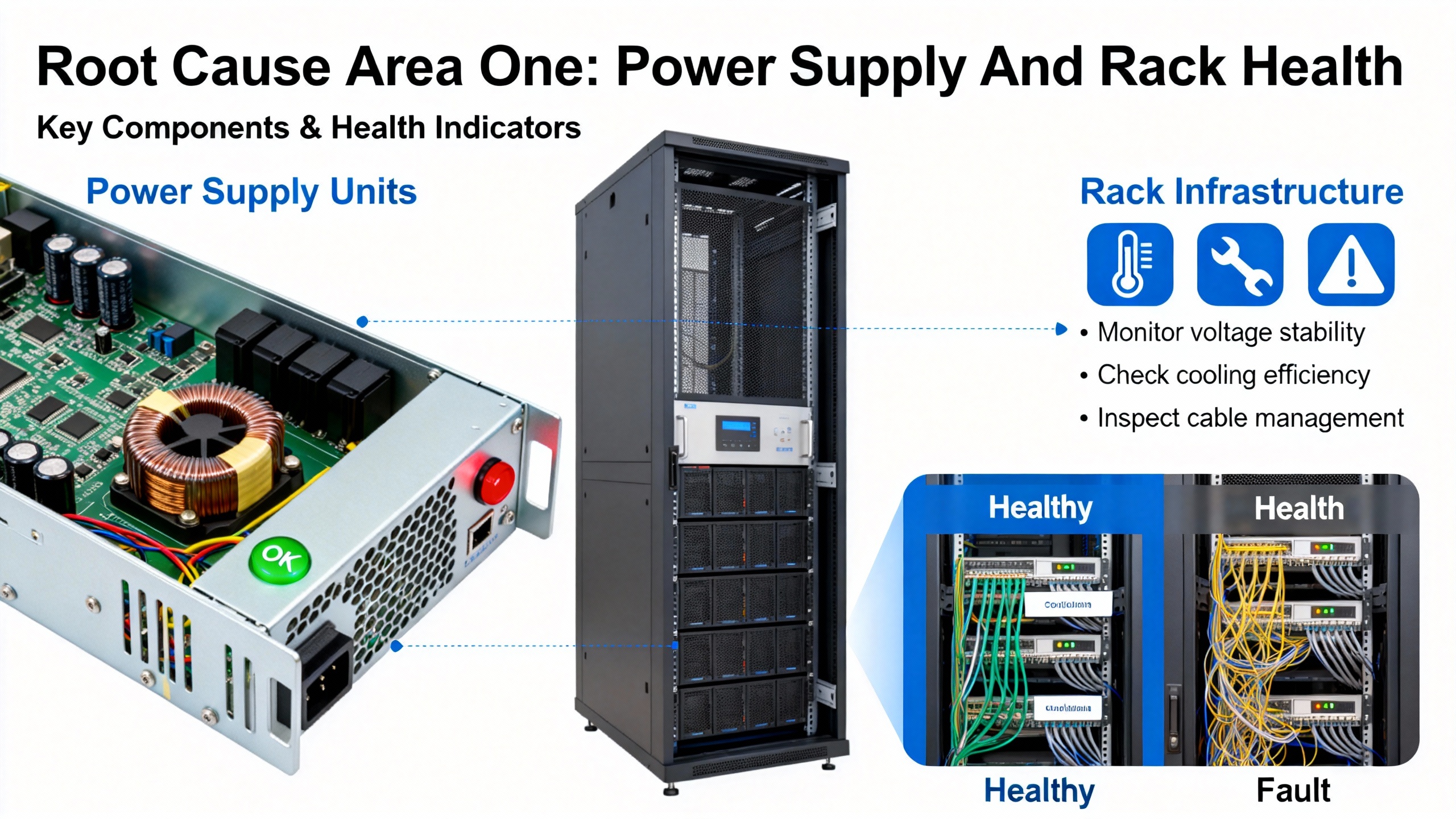
Root Cause Area One: Power Supply And Rack Health
Power supply issues are one of the most common triggers for widespread 3500 faults. The ActechParts summary of the official documentation explicitly calls out power source interruption, faulty power supply modules, and improper installation as frequent causes of power-related failures. The recommended first steps are to verify power connections, replace defective modules, and cross-check against the installation guidelines.
Ubest AutomationŌĆÖs troubleshooting article echoes this from a plant-maintenance angle. In their experience, voltage fluctuations on the supply feeding the rack can produce unexpected shutdowns or repeated alarms. Their recommended practices are to verify the power input to the rack using the relevant indicators and test equipment, and to closely inspect the power supply modules. Any unit showing a red fault light should be treated as suspect and replaced with a compatible, known-good module.
In the field, power issues often manifest as several modules dropping out together or a combination of AC OK and DC OK LEDs flickering or going dark. When multiple modules simultaneously show FAIL or NOT OK after a disturbance, it is more efficient to treat the problem as rack-level power first rather than chasing each monitor individually.
From a reliability perspective, consistently clean and correctly sized power to the 3500 rack is part of your protection system design. The manufacturerŌĆÖs specifications, as summarized by ActechParts, include detailed electrical requirements. Verifying that your installation matches those requirements is not just a commissioning task; it should be part of any systematic review after unexplained monitor outages.
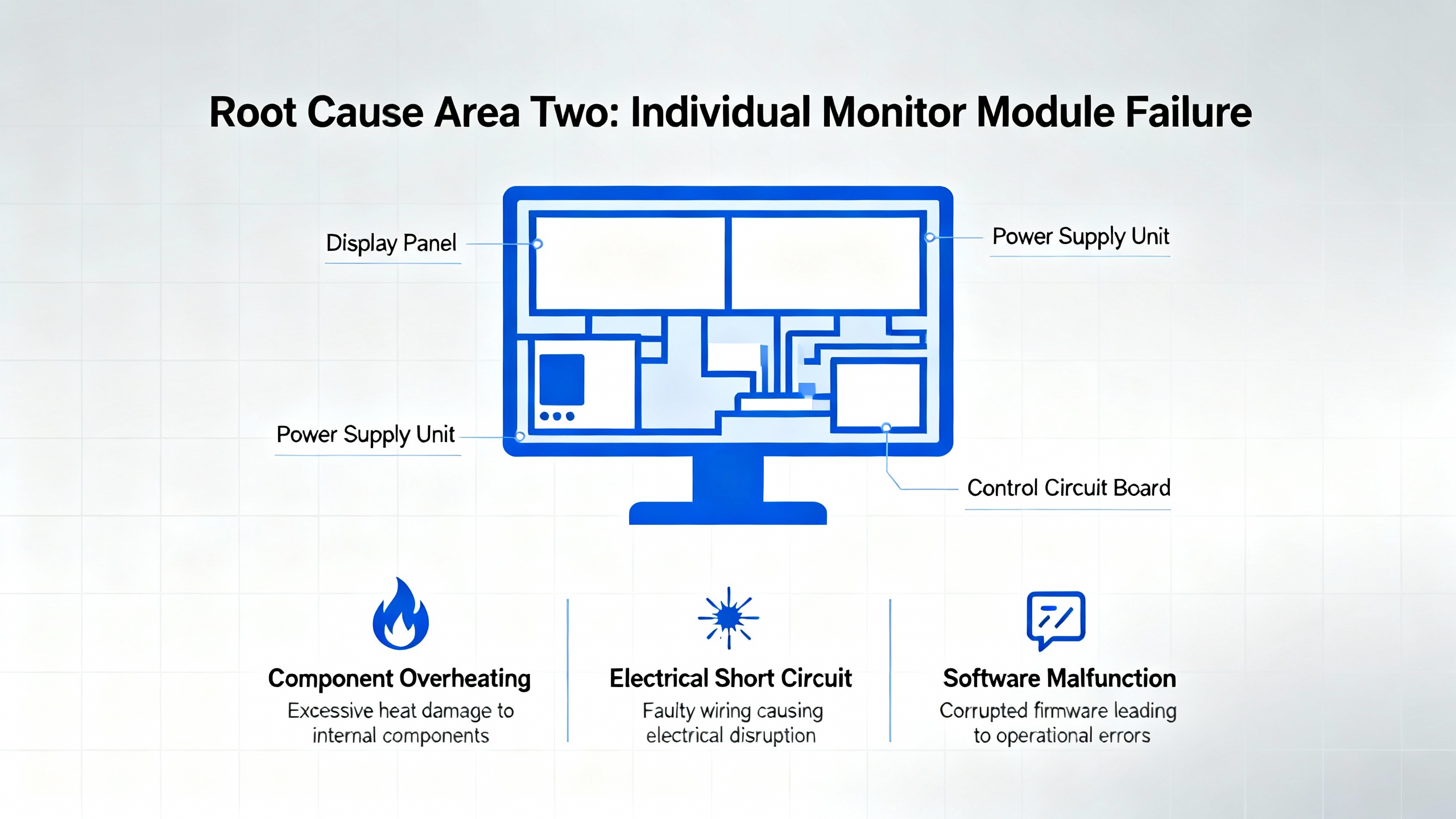
Root Cause Area Two: Individual Monitor Module Failure
When power is stable and other modules appear healthy, attention naturally shifts to the suspect monitor card itself. A typical pattern is a single vibration monitor such as a 3500/42M showing intermittent FAIL indications while adjacent cards stay OK.
UbestŌĆÖs LED article describes a real-world case on a gas turbine where a 3500/42M vibration monitor showed intermittent FAIL. Visual inspection of connectors and wiring did not reveal any obvious issues, and reseating the module in the rack did not provide a lasting fix. The problem was resolved only after the monitor was replaced with a certified compatible unit, after which operation stabilized and the original card was sent for repair.
UbestŌĆÖs broader troubleshooting guidance reinforces this ŌĆ£swap to proveŌĆØ approach. When a specific monitor module is triggering channel alarms or FAIL indications and the sensors and wiring look sound, a standard practice is to replace that module temporarily with an identical spare. If the problem follows the module, the hardware is the likely culprit. If the fault stays with the rack slot or channel even after the swap, it suggests wiring, configuration, or backplane-related causes.
ActechParts notes that a ŌĆ£Module Not RespondingŌĆØ fault in the 3500 ecosystem is often tied to either power problems or module malfunctions, and that the official guidance in such cases is to verify power first, then replace the malfunctioning module and reconfigure its settings as necessary.
From a reliability advisorŌĆÖs perspective, the key is not to normalize intermittent FAIL indications on modules that are protecting high-criticality assets. Persistent or recurring fault states justify proactive module replacement and repair, rather than repeated resets that may leave the machine exposed.
Root Cause Area Three: Communication And Gateway Issues
Not every ŌĆ£dead monitorŌĆØ complaint originates in the rack. Communication gateway modules and network infrastructure can create the appearance of monitor failure when the underlying measurements are actually healthy.
An instructive case from an Automation and Control Engineering forum describes frequent communication failures between a Mark VIe control system and Bently Nevada 3500 vibration monitoring racks on four gas turbine units. Operators reported that vibration data disappeared from HMI screens, while turbine control and process data remained available. This failure rotated across all four machines within less than an hour.
The configuration included a 3500/92 EGD Communication Gateway module serving as the bridge between each 3500 rack and the Mark VIe system. On one unit, the gatewayŌĆÖs COMM LED was off and its OK LED was flickering. On the other three units, COMM was on and OK was solid green, yet data still intermittently failed to reach the HMIs. In parallel, the EGD server services on the Mark VIe workstation showed normal status. Using the Bently Nevada rack configuration utility on a separate laptop, technicians confirmed that all vibration channels and modules in the 3500 racks were OK, but the 3500/92 gateways reported status as NOT OK.
This type of pattern strongly suggests that the 3500 monitor modules themselves are healthy and that the point of failure lies in the communication gateway or the network path beyond it. UbestŌĆÖs common-issues guide supports that interpretation: they highlight that communication failures between 3500 and DCS or PLC systems are frequently rooted in cabling problems, incorrect protocol or IP settings, or faulty networking hardware such as switches. Their recommended checks include verifying network cabling and connectors and confirming all communication parameters in the configuration software.
In a separate case from Ubest, repeated communication drops between a 3500 system and an AllenŌĆæBradley PLC were eventually resolved by replacing a defective network switch and updating firmware. Once the switch was replaced, data flow stabilized without needing to replace the monitoring hardware.
The takeaway is that when vibration data is missing on supervisory systems yet the 3500 rack shows healthy LEDs and channel data locally, you should suspect the communication chain: gateway module, network switches, and configuration, before condemning the monitor cards.
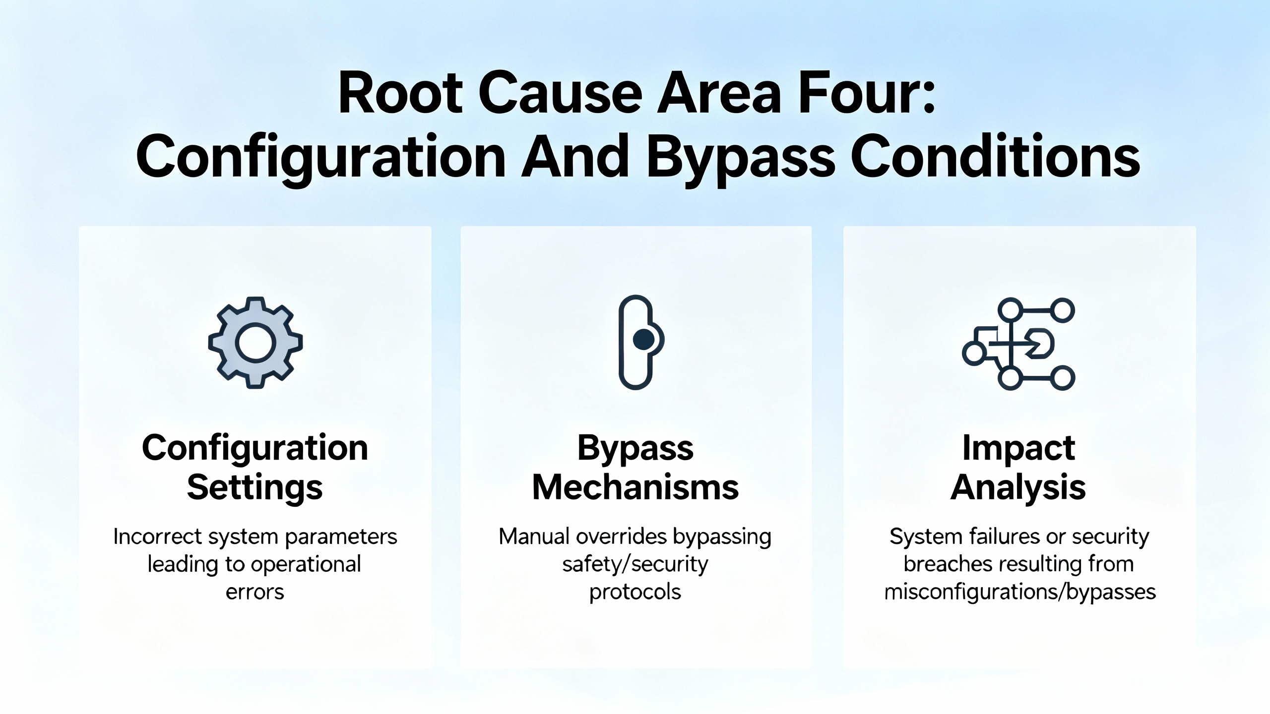
Root Cause Area Four: Configuration And Bypass Conditions
Modern protection systems are as dependent on correct configuration as they are on sound hardware. Misconfigured modules can appear ŌĆ£not workingŌĆØ even when every electronic component is healthy.
UbestŌĆÖs LED interpretation article specifically warns that a blinking OK LED is often associated with bypass conditions or configuration mismatches. That may mean a channel has been intentionally bypassed and never restored to service, or that the moduleŌĆÖs configuration does not match the rack or system expectations. Either way, leaving a blinking OK state unaddressed can mean that a protection loop is not actually armed.
ActechPartsŌĆÖ summary of the official documentation notes that ŌĆ£Module Not RespondingŌĆØ faults can be linked to configuration errors in addition to power and hardware problems. Their recommended corrective actions include reconfiguring module settings using the authorized configuration tools, and comparing that configuration with the installation and ordering information.
UbestŌĆÖs troubleshooting guide also points to configuration errors as a frequent root cause of operational faults. They highlight issues such as incorrect setpoints, alarm values, or logic, and they emphasize always backing up the configuration before making changes, verifying all key parameters, and reloading known-good configurations when inconsistencies are suspected.
From a reliability standpoint, configuration management for 3500 racks should be treated similarly to protection relay settings in power systems. Unauthorized or undocumented changes can be just as dangerous as hardware failures. When a monitor is not behaving as expected but LEDs and wiring look normal, pulling a configuration report and comparing it to a baseline is essential.
When The Sensors Are The Culprit, Not The Monitor
There is another class of ŌĆ£monitor not workingŌĆØ complaints where the monitor module is actually doing its job: it is accurately reporting a bad or missing signal from the field. If you skip sensor diagnostics, you may end up replacing an expensive module when the real problem is a damaged probe or cable.
InstrumentationTools presents a step-by-step troubleshooting guide for vibration monitoring systems using Bently Nevada 3500 hardware as a reference. Their workflow starts with the sensor chain: proximity probe, extension cable, and proximitor. First, they recommend a careful visual inspection of the probe tip, cable, extension cable, and proximitor for signs of mechanical damage, contamination, or wear. They also stress ensuring all connectors are tight and properly insulated, and they explicitly call out the importance of using the original equipment manufacturerŌĆÖs junction tape to insulate bare sections instead of generic tape that may allow noise ingress.
The next step in their method is to measure the probe gap voltage and observe it for roughly ten to fifteen seconds. This voltage should remain stable around the systemŌĆÖs specified value, which is often around a negative setpoint such as ŌłÆ7.5 V or ŌłÆ10 V depending on design. Applying a light mechanical jerk to the probe cable and the probe while watching this voltage is a simple but effective test: if the voltage fluctuates when the cable is moved, there is likely a fault in the probe or cabling.
If these checks look satisfactory, the guide suggests carefully removing the probe, marking its position or counting exposed threads to preserve alignment, and inspecting the probe tip for foreign material or physical damage. Any contamination or wear should prompt both mechanical root-cause investigation and probe replacement as required.
Farther into the chain, the guidance recommends measuring the electrical resistance of the probe and extension cable and comparing the results to the manufacturerŌĆÖs specified ranges for the exact model. They then advocate for a micrometer-based test to confirm that the complete measurement chain (probe, extension cable, and proximitor) responds linearly as the target moves. Non-linear behavior usually indicates a defective component.
To isolate which component is faulty, the recommended approach is substitution: test the existing probe with a known-good extension cable and proximitor, then test the existing extension cable and proximitor with a known-good probe, looking for combinations that produce non-linear or unstable readings. Once a defective component is identified and replaced, the full chain should be retested, the probe reinstalled and secured, and the gap voltage reset to its required system value.
This level of sensor-chain troubleshooting may seem outside ŌĆ£module failure,ŌĆØ but in practice it is tightly coupled. Many apparent monitor faults come down to a bad signal at the input. A structured sensor test sequence prevents unnecessary module replacement and restores confidence in the entire loop, from bearing to screen.
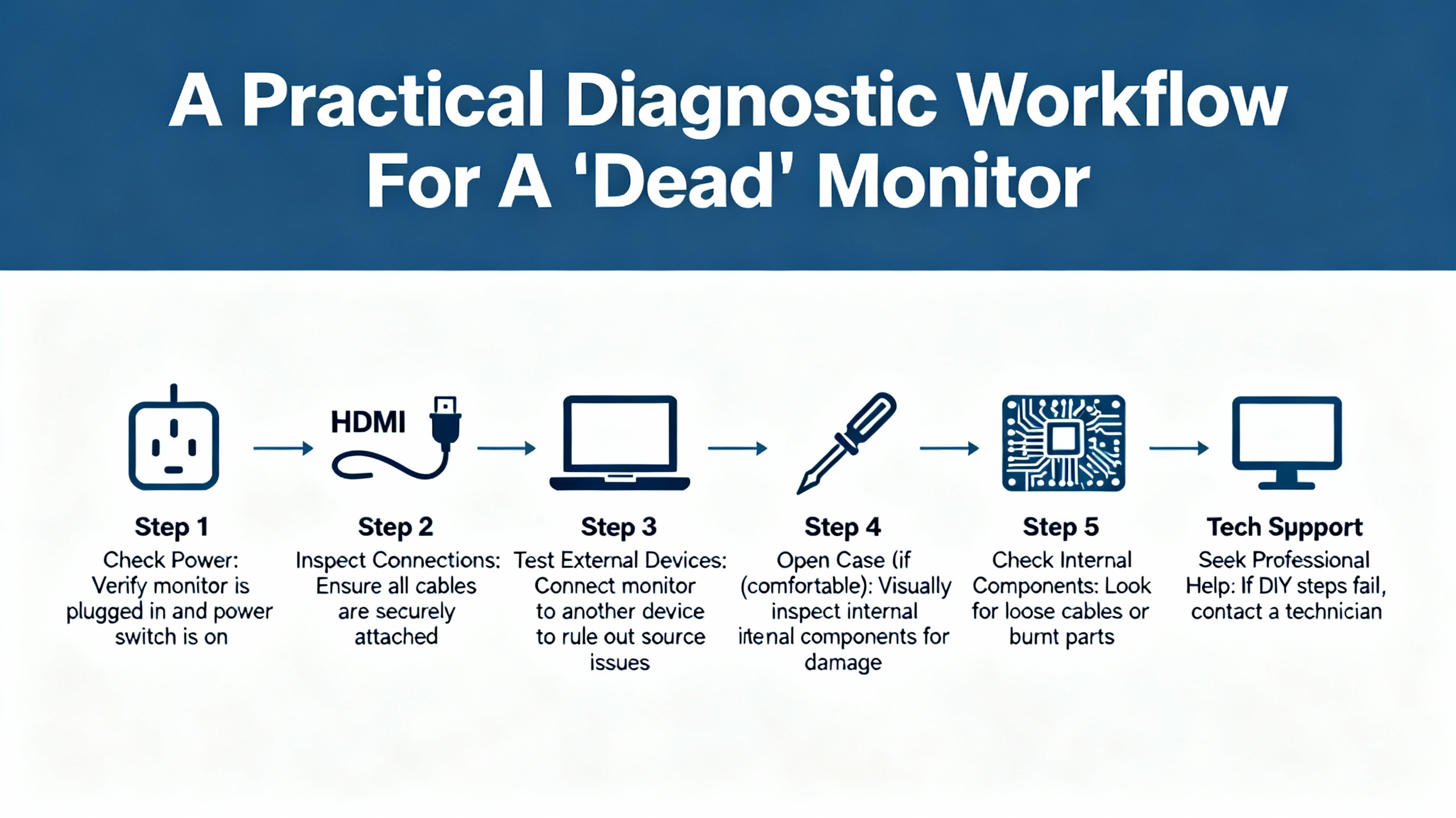
A Practical Diagnostic Workflow For A ŌĆ£DeadŌĆØ Monitor
Bringing these threads together, a structured diagnostic approach keeps you from chasing symptoms in circles. When a 3500 monitor appears not to be working, it is helpful to move from the most global, cross-cutting causes toward the most specific.
Start at the rack level and look at the power picture. Confirm power supply health using the AC OK and DC OK indicators on the power module and by checking that other modules do not share the same fault pattern. If several modules show FAIL or NOT OK together, or if the rack has recently lost power, prioritize verifying the power source, its stability, and the power supply module itself. This aligns with the manufacturer-style recommendations summarized by ActechParts and with UbestŌĆÖs emphasis on resolving power issues before anything else.
Once rack power is deemed healthy, focus in on the suspect moduleŌĆÖs front-panel indicators. Interpret the OK, FAIL, TX, and any channel LEDs using the patterns described by Ubest. A steady OK with no alarms points away from hardware failure, while a solid FAIL or complete absence of OK points squarely toward a card problem. A blinking OK should prompt you to review configuration and bypass settings, not just hardware.
Next, correlate what the rack believes with what higher-level systems see. If the module appears OK at the rack and channel LEDs show normal behavior, yet the DCS or HMI does not show data, you are likely in a communication-fault scenario. Use any gateway-specific utilities, such as the rack configuration software mentioned in the Mark VIe case, to check the status of communication modules like the 3500/92 EGD gateway. If those report NOT OK while the monitor channels are healthy, that is your immediate suspect. At the same time, follow UbestŌĆÖs guidance by verifying cabling, connectors, and key protocol or IP settings, and by considering the health of intermediate network devices such as switches.
In parallel, or as soon as you suspect that the module is behaving but readings look unreasonable, apply the sensor-chain techniques from InstrumentationTools. Confirm that probes, cables, and proximitor units present stable gap voltage, clean mechanical integrity, and linear response. Many ŌĆ£bad monitorŌĆØ complaints evaporate once a faulty probe tip or damaged cable is identified and replaced.
Only after these steps should you commit to replacing the monitor module itself. When you do, follow the disciplined approach outlined in UbestŌĆÖs troubleshooting guide: swap with a compatible spare, verify that the fault moves with the module, and then correctly configure the replacement. Finally, use the TDI and RIM diagnostics described by ActechParts as a deeper check, connecting a portable computer to gather event logs, verify settings, and confirm that the rackŌĆÖs overall configuration is consistent and healthy.
For complex or persistent issues that survive this workflow, both ActechParts and Ubest point toward involving vendor or specialist support. At that stage, you want detailed notes on LED patterns, alarm codes, configuration versions, and any recent power or network events so that external experts can replicate your reasoning and add their own.
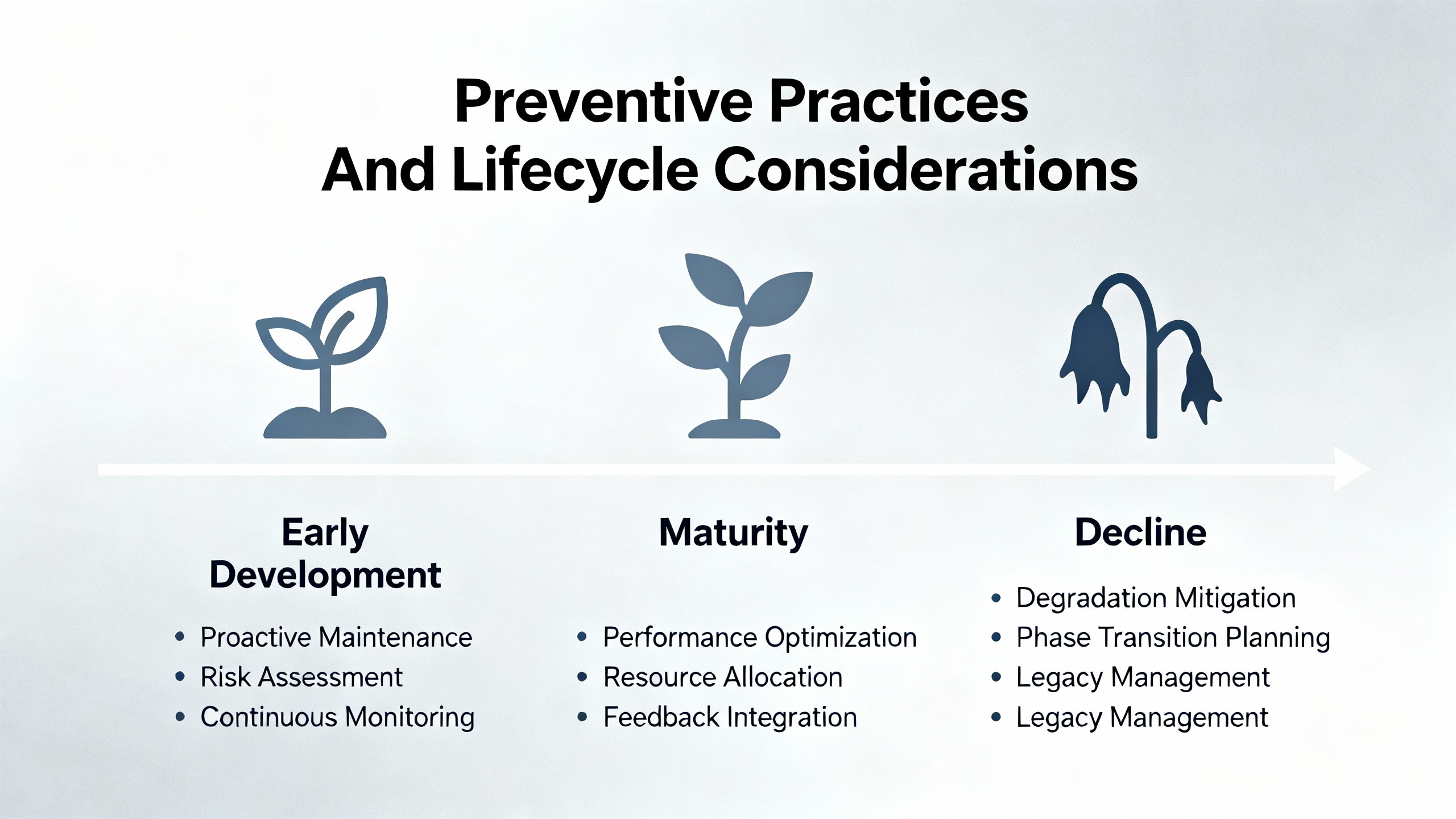
Preventive Practices And Lifecycle Considerations
Module failure diagnostics are only half the story. The other half is reducing the likelihood of those failures in the first place and managing lifecycle risk as hardware ages.
Baker Hughes, the current steward of Bently Nevada, has published a lifecycle perspective on the older 3300 monitoring platform that is instructive. They note that the 3300 system has already passed through phases of limited spare support and was declared obsolete, with repairs ending years ago. Wear-out components such as electrolytic capacitors, relays, buttons, and memory devices have finite lifespans in the range of roughly a decade or two, meaning even spare modules quietly age on the shelf.
Their recommendation for plants that still rely on 3300 hardware is to conduct annual health checks by qualified service personnel, including rack inspection, communication verification, full calibration, relay logic checks, and full transducer loop validation, followed by a formal condition report. They also advocate for proactive migration to current platforms such as the 3500 series or other modern monitors integrated with System 1 software for advanced diagnostics.
While the 3500 platform remains in active support, the same principles apply. UbestŌĆÖs troubleshooting article emphasizes proactive maintenance such as periodic cleaning of modules, checking and tightening connections, and keeping firmware up to date. These practices reduce random faults and extend overall system life. Incorporating monitor status checks, LED inspections, and selective configuration reviews into your routine maintenance rounds prevents minor issues from accumulating into full-blown monitor outages.
At the software level, Baker HughesŌĆÖ discussions of System 1 and its Bently Performance module highlight another dimension of protection-system reliability. By correlating high-resolution vibration data from 3500 racks with process and performance metrics, operators can identify subtle degradation trends and anomalies earlier, long before modules start failing or protection thresholds are reached. Although this goes beyond basic module failure diagnosis, it strengthens the argument that monitoring health, configuration quality, and performance analytics all live in the same reliability ecosystem.
FAQ
What does a ŌĆ£Module Not RespondingŌĆØ alarm actually mean on a Bently Nevada 3500 rack? Based on the ActechParts summary of the official documentation, this alarm is usually associated with one of three cause areas: loss or instability of the power supply feeding the module, an internal hardware malfunction of the module itself, or a configuration error that prevents the rack from recognizing or communicating with the module. The recommended response is to verify rack power, inspect and possibly replace the suspect module, and then review and correct its configuration settings using the authorized tools.
Can a single failed monitor module compromise the protection of an entire machine train? It can, depending on how your protection logic is structured. UbestŌĆÖs LED interpretation article notes that a single module fault can disable an entire protection loop in some architectures. If that module is responsible for key shutdown votes or critical machine sections, leaving it failed or in bypass undermines the protective coverage. That is why LED checks and alarm reviews should be part of daily operational routines, not just reactive responses.
When is it time to involve external specialists instead of continuing to troubleshoot internally? Both Ubest and the ActechParts guide converge on the idea that persistent, recurring, or multi-system issues justify bringing in specialist support. Examples include communication failures that appear across multiple units, repeated ŌĆ£Module Not RespondingŌĆØ alarms after hardware replacement, or complex interactions between configuration, performance, and protection logic. At that point, the most productive step is to provide a complete record of events, diagnostics, and changes to a vendor or reliability partner who can apply deeper tools and broader experience.
A Bently Nevada monitor that is not working is really a protection system that is not fully trustworthy. By combining disciplined observation of LEDs and alarms, structured sensor and module testing, communication-path verification, and proactive maintenance, you can restore that trust and keep your critical equipment safely within its protective envelope. As a reliability advisor, I would frame success here very simply: when your machines run hard, the monitors and protection logic guarding them should be the least of your worries.
References
- https://do-server1.sfs.uwm.edu/upload/@32405536MF/play/21287FM/bently+nevada+1701+user+manual.pdf
- https://assetmanagementprofessionals.org/discussion/bently-rack-protection-and-the-not-ok-signal
- https://www.machineryanalysis.org/post/troubleshooting-orbit-analysis-using-bently-nevada-system-1-10170139
- https://studylib.net/doc/27017185/bently-nevada-3500-proximitor
- https://www.plctalk.net/forums/threads/bently-3500-92-prosoft-mvi56e-mnet-comm-woes.120249/
- https://actechparts.com/bently-nevada-3500-complete-guide/
- https://www.artisantg.com/info/GE_Bently_Nevada_3500_33_01_Manual_20184271141.pdf?srsltid=AfmBOoqzl0INKsqWl4CXJUqbLlFgdUDPcMdGHepGSGkZpEtxCteYpweo
- https://gvn.biz/bently-nevada-vibration-monitoring-and-equipment-diagnostics/
- https://instrumentationtools.com/vibration-monitoring-system-step-by-step-troubleshooting-guide/
- https://www.powergearx.com/bently-nevada-probe-health-a-guide-for-industrial-automation/


 Videos
 News
News Applications


Leave Your Comment