As a power system specialist who sees Bently Nevada racks living sideŌĆæbyŌĆæside with UPSs, inverters, and power protection gear, IŌĆÖve learned this the practical way: a ŌĆ£System AlertŌĆØ or ŌĆ£Not OKŌĆØ on a 3500 monitor is rarely a single fault in isolation. It is a chain. Power quality, network behavior, and instrumentation health all influence whether your machinery protection stays trustworthy. This guide walks through what those alerts mean, how to triage them quickly, and how to harden your system so they do not recur.
What ŌĆ£System AlertŌĆØ and ŌĆ£Not OKŌĆØ Really Mean
On a Bently Nevada 3500 rack, the ŌĆ£OK/Not OKŌĆØ status tells you whether the monitor channel, module, or rack believes the instrumentation chain is healthy. A ŌĆ£Not OKŌĆØ is not a vibration overlimit; it is a selfŌĆædiagnostic result that usually points toward instrumentation or system health, not the machineŌĆÖs condition. By contrast, ŌĆ£AlertŌĆØ and ŌĆ£DangerŌĆØ are alarm levels based on measured values and setpoints. An ŌĆ£AlertŌĆØ indicates conditions that need attention; ŌĆ£DangerŌĆØ is used for protection and trips.
Some system alerts present as missing or stale vibration values on the HMI while other process values remain normal. In Mark VIe environments, vibration is often carried from 3500 racks via the 3500/92 EGD Communication Gateway. When the gateway reports ŌĆ£NOT OK,ŌĆØ or when the HMI shows no vibration while it continues to show temperature and process data, the path from rack to HMI is the suspectŌĆöoften a gateway, exchange mapping, or network behavior issueŌĆörather than the transducer chain itself. Forum discussions on Control.com describe this exact pattern, including normal WorkstationST services yet intermittent or sequential vibration data loss across multiple units. In those cases, the vibration path failed while the rest of the DCS stayed healthy.
Within the rack, ŌĆ£OKŌĆØ supervision checks the probe, extension cable, Proximitor, and the monitor module itself. A true measurement problem will frequently appear as a ŌĆ£Not OKŌĆØ on a channel or module before it ever elevates to a process alarm. That is by design: it prevents nuisance trips due to instrument faults rather than machine faults.
FirstŌĆæResponse Triage: Prove the Basics First
Field teams move fastest when they follow a consistent, short diagnostic loop. Start with power integrity at the rack, then confirm the communications path and addressing, then verify the sensor chain and the module health, and finally review configuration integrity. In my commissioning work, forcing myself to follow that order prevents rabbit holes and ŌĆ£fixingŌĆØ the wrong thing. Power and network faults are amplified in any highŌĆæavailability system; they can masquerade as random instrument failures and trigger ŌĆ£Not OKŌĆØ on modules that are perfectly sound.
If the symptom is widespreadŌĆösequential loss across multiple machines, repeating every few minutes or hoursŌĆösuspect something shared. Look at the network VLAN behavior, switch logs, or gateway resources rather than any one probe or card. If the symptom is isolated to one channel, prove the transducer chain first.
Power Integrity and Protection Considerations
Protection systems ride on the quality of their power. The 3500 rack supports redundant power supplies; use that redundancy and feed it from clean, protected sources. In plants, I specify an industrial UPS with adequate rideŌĆæthrough, surge suppression upstream of the UPS, and coordination with facility grounding to prevent ground noise coupling into probe circuits. Rack supplies can be in good electrical shape while still seeing disturbances that degrade their stability. A sag lasting less than a second may never trip the UPS alarm, but it can still flicker an ŌĆ£OKŌĆØ LED and produce ŌĆ£Not OKŌĆØ on instrumentation that is sensitive to reference stability.
Give the rack its own clean branch, avoid sharing with switching power supplies that throw harmonics back on the line, and separate sensor power and rack power where practical. When you troubleshoot, record input voltage and ripple at the rack terminals, reseat the power modules, and validate that both redundant supplies carry load. If you see intermittent ŌĆ£Not OKŌĆØ or flicker on ŌĆ£OKŌĆØ LEDs, and it correlates with transfer events upstream, deepŌĆædive power before you replace modules. If power problems persist, a UPS with a doubleŌĆæconversion topology, proper surge protection devices, and coordinated grounding will often stabilize the platform without touching the instrumentation.
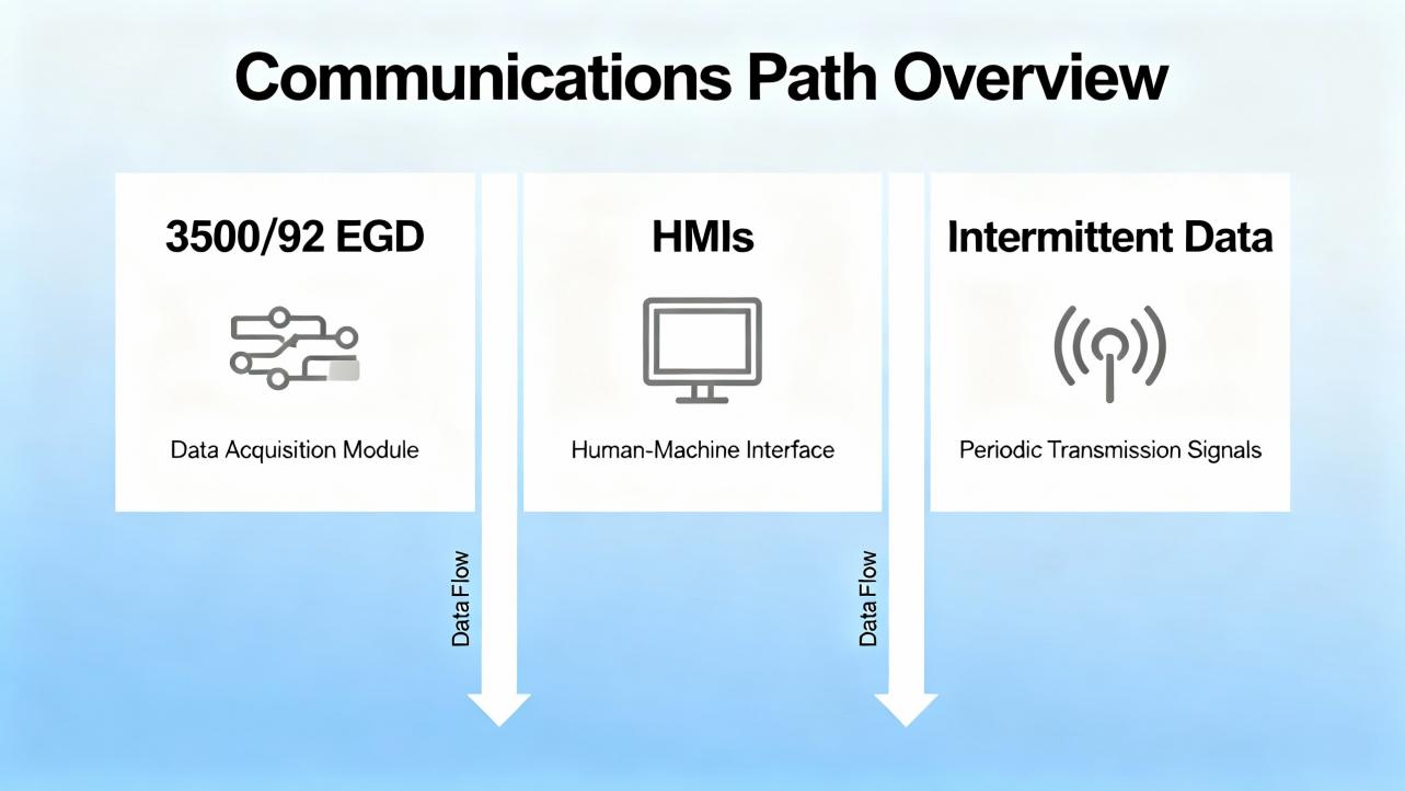
Communications Path: 3500/92 EGD, HMIs, and Intermittent Data
In Mark VIe integrations, the 3500/92 EGD gateway publishes vibration data as Ethernet Global Data over UDP multicast or unicast. Control.com posts detail episodes where vibration disappears from HMIs across units while other HMI data remains normal. The 3500/92 sometimes shows ŌĆ£NOT OKŌĆØ in the configuration tool while channels are ŌĆ£OK,ŌĆØ pointing to the gateway or network rather than the sensors. Frequent root causes include mismatched producer or exchange IDs, wrong multicast settings, duplicate IP or MAC addresses, switch storms, or IGMP snooping misconfiguration. Because EGD is UDP, loss presents as stale or missing values rather than handshake errors.
Begin by validating addressing: IP, subnet, and producer IDs on the 3500/92 versus the HMI consumers. Confirm exchange maps, multicast groups, and TTL. Inspect switches for port flaps, error counters, and broadcast or multicast storms. IGMP snooping should be paired with a querier on the VLAN that carries vibration. Segregate vibration traffic into a dedicated VLAN if necessary, and rateŌĆælimit where storms have been suspected. If one gateway alone shows COMM LED off while ŌĆ£OKŌĆØ flickers, reseat or powerŌĆæcycle the gateway during a controlled window and consider a firmware update approved by your change process. If you observe a sequential failure pattern across multiple trains, the network is frequently the common denominator.
| Symptom | Likely cause or constraint | Fast checks and fixes |
| HMI shows process data but vibration is missing across many units | EGD multicast not reaching consumers; switch storm or IGMP misconfig | Validate exchange IDs and multicast; enable IGMP snooping and a querier; check switch logs and drop counters |
| One 3500/92 COMM LED off; OK flickers | Gateway fault, power dip, or duplicate IP/MAC | Reseat or powerŌĆæcycle; verify clean power; use ARP scans for duplicates; consider tested firmware revisions |
| Only one machine affected; channels show ŌĆ£OK,ŌĆØ gateway ŌĆ£NOT OKŌĆØ | Mismatch in producer/consumer configuration | Align producer ID and exchange maps; confirm unicast versus multicast settings |
| Vibration losses align with other network congestion events | VLAN saturation; broadcast/multicast storm | Isolate traffic to a VLAN; apply rate limits; review storm control and spanningŌĆætree convergence parameters |
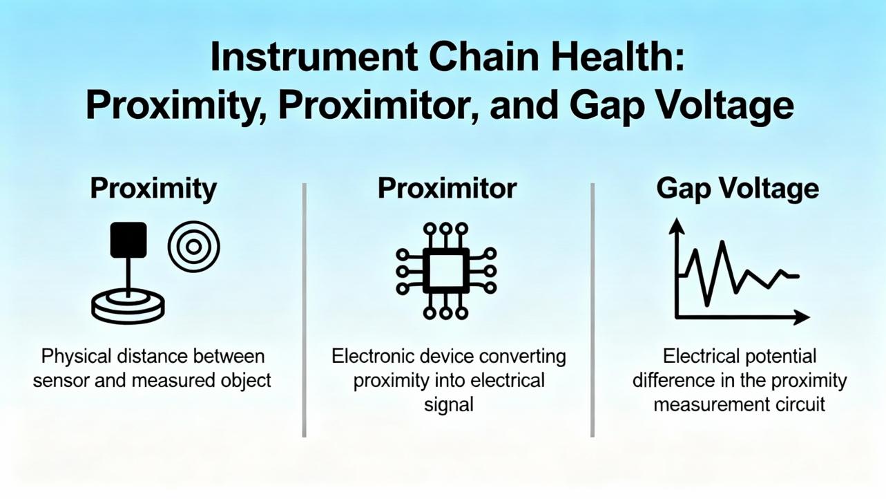
Instrument Chain Health: Proximity, Proximitor, and Gap Voltage
For shaft vibration and position, the transducer chain includes the probe, the extension cable, and the Proximitor driver, and these components are a matched set. Any mismatch reduces linearity and makes calibration meaningless. InstrumentationTools explains the field checks well: start with a visual inspection and connector integrity, then verify the gap voltage. The steady DC bias should remain stable over 10 to 15 seconds. A light ŌĆ£jerkŌĆØ on the cable should not move the voltage; if it does, suspect wiring, connector integrity, or probe contamination. On removal and reinstallation, mark the number of threads so you can return to the same initial gap. If a probe tip shows debris or rub marks, involve the mechanical team and address root cause before swapping parts.
When you suspect nonlinearity, replace one component at a time with a knownŌĆægood element: first the probe, then the extension cable, then the Proximitor. Use a micrometer to verify the linear response over a short travel. If the system fails to track linearly, keep isolating until you find the element that breaks calibration. After replacement, restore the original chain unless your testing confirmed a defective part. Maintain the bias voltage per machine configuration. Manuals may show negative DC bias values common to eddyŌĆæcurrent systems, but model specifics vary; follow the official monitor documentation for your exact transducer set.
Contamination, poor cable dressing, improper shielding, and ground loops are the quiet killers of good vibration data. Route cables away from highŌĆænoise conductors, avoid parallel runs with VFD feeders, and follow the OEMŌĆÖs guidance for shield terminations. Use the correct insulating tape at probeŌĆæextension junctions rather than generic thread sealants, because the wrong material can add noise and moisture paths.
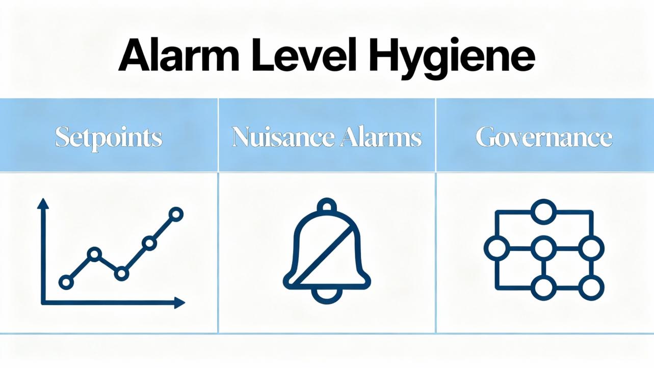
Alarm Level Hygiene: Setpoints, Nuisance Alarms, and Governance
Baker HughesŌĆÖ Orbit magazine explains why alarm levels deserve operational discipline. Overall severity alarm practices are useful for protection and acceptance testing, but they do not capture the full richness of spectral data. A sensible approach is to baseline new or newly overhauled machines, record healthy data, and then create thresholds relative to that baseline. Some teams add a fixed velocity increment, such as about 0.08 in/s above baseline, sometimes combined with a multiplier, such as 1.6 times the healthy level. Others apply statistical techniques, adding a multiple of standard deviation to the mean. Whatever you choose, make editing rights clear; uncontrolled changes made by different stakeholders lead to confusion and alarm fatigue.
Nuisance alarms come from misapplied setpoints, misŌĆæscaled channels, insufficient dynamic range, overloaded sensors, or wrong sensor types. When alarms fire, analyze the signal, not just trends, and validate the instrumentation health first. If you must temporarily raise thresholds while you investigate, timeŌĆælimit the change, document it, and restore normal levels. After a trip, always mine preŌĆæ and postŌĆæevent data to understand root cause; use that to refine alarm strategy without masking hazards.
| Use case | Recommended approach |
| Baseline a newly commissioned machine | Capture stable data at steadyŌĆæstate; set thresholds relative to this baseline with a fixed increment |
| FastŌĆæmoving process changes | Add learningŌĆæbased or statistical thresholds in analytic platforms; keep setpoints auditable |
| Control room visibility | Keep only high/highŌĆæhigh for protection; route granular alarms to the reliability platform |
| Alarm hygiene | Maintain an alarm log, color codes, and change history; avoid adŌĆæhoc edits across teams |
Diagnostics Workflow for Known ŌĆ£System AlertŌĆØ Patterns
A few patterns recur in plants. When the HMI loses vibration across multiple units in a predictable, sequential way, the issue is usually in the networkŌĆÖs handling of multicast EGD or in a shared firewall or switch. I have traced this to missing IGMP queriers, spanningŌĆætree reconvergence, and broadcast storms. When a single gateway shows COMM LED off while its OK LED flickers and others are stable, you are likely seeing a gateway fault or power disturbance, not a plantŌĆæwide network failure. If the configuration software shows the rack ŌĆ£OKŌĆØ and channels ŌĆ£OK,ŌĆØ but the EGD gateway ŌĆ£NOT OK,ŌĆØ you are hunting a producer/consumer mismatch or a resource fault in that gateway. When one channel alone reports ŌĆ£Not OK,ŌĆØ it is almost always in the transducer chain; the micrometer test and a methodical substitution with a knownŌĆægood probe or cable quickly reveals the culprit.
Within reliability teams, it helps to record the time alignment between ŌĆ£System Alert,ŌĆØ power quality events, and network events. I log transfer times on the UPS, voltage sags at the MCC, and switch logs for multicast changes. Those correlations often shrink a dayŌĆÖs investigation into an hour.
Safety and Protection Assumptions
The older Bently Nevada 3300 troubleshooting manuals, republished in places like Scribd, place warnings and cautions upfront for a reason. Calibration can temporarily disable protection functions; doing so on a running machine without a safe state and a documented plan defeats the entire purpose of machinery protection. Treat any ŌĆ£System AlertŌĆØ on a protection rack as a serious safety signal until you prove it benign. If you need to disable channels for testing, coordinate with operations, implement temporary risk controls, and document the exposure window. There is no productivity benefit that justifies a blind override when bearings and rotors are at stake.
Care, Maintenance, and Buying Tips
Care starts with cleanliness, physical connection integrity, and configuration backups. I schedule quarterly inspections to reŌĆæseat modules, clean contacts, and verify all field connectors for torque and shielding. I also keep firmware under change control, and I export knownŌĆægood configurations whenever I make setpoint edits or channel changes. On the lens of lifecycle cost, these habits are more valuable than any individual spare part.
When you buy spares, insist on matched probeŌĆōextensionŌĆōProximitor sets from the same family, because mixing elements destroys linearity and voids calibration assumptions. For gateways, confirm product support status and firmware availability before purchasing used units. For network gear that carries EGD, choose managed switches with IGMP snooping, a querier capability, and clear diagnostics, and place vibration data on a dedicated VLAN if the plant network is busy. On power, favor doubleŌĆæconversion UPSs for the rack supply and surge protection upstream, with spare rack power modules on the shelf. Lastly, vet suppliers for authenticity and traceability; the false economy of lowŌĆæcost sensors or ŌĆ£equivalentŌĆØ drivers disappears the instant your data turns untrustworthy.
| Item or decision | What to look for | Why it matters |
| Probes and Proximitors | Matched sets from the same model family; OEM insulating tapes and connectors | Maintains calibration and linearity; reduces noise and moisture ingress |
| 3500 rack power modules | Redundant supplies, tested on both phases; feed from a clean UPS | Eliminates false ŌĆ£Not OKŌĆØ from dips and sags; preserves protection during disturbances |
| 3500/92 gateway | Supported firmware, knownŌĆægood configuration backups | Reduces risk of EGD resource faults and configuration drift |
| Network switches | Managed, with IGMP snooping and a querier; VLAN segregation for vibration traffic | Prevents multicast loss and storms; speeds diagnostics |
| Configuration management | Regular exports, change logs, and access controls | Avoids silent setpoint drift and undocumented changes |
When to Escalate and What Data to Capture
Escalation goes faster when you collect the right evidence. Capture screenshots of channel status, ŌĆ£OK/Not OKŌĆØ indications, and gateway diagnostics; export 3500 configuration files and EGD exchange maps; pull switch logs and port counters; and record time stamps of the alert alongside any UPS transfer or power event. If the HMI is missing vibration, capture the HMIŌĆÖs time stamps, the Mark VIe diagnostics for EGD subscriptions, and any alarm viewer events in WorkstationST. For instrumentation, include photos of probe tip condition, measured bias voltages, and linearity checks. This package enables a vendor to move from speculation to root cause without a repeat site visit.
A Practical Example: Resolving Repeating Communication Loss
Consider a case described by practitioners on the Control.com forum: four gasŌĆæturbine trains, each with a 3500 rack and a 3500/92 gateway feeding Mark VIe HMIs, saw their vibration values disappear sequentially with a recurrence under an hour. Racks reported channels ŌĆ£OK,ŌĆØ yet EGD gateway status read ŌĆ£NOT OK,ŌĆØ and one gatewayŌĆÖs COMM LED was off while its OK was flickering. This pattern is textbook for a network behavior conflict rather than simultaneous instrumentation failures. Validating exchange IDs and producer IDs, enabling IGMP snooping with a querier on the correct VLAN, and checking for duplicate IP or MAC entries typically resolves the cascade. In some plants, a firmware refresh and reseating a flaky gateway restores stability. When the data loss migrates from one unit to another on a schedule, always ask what the network is doing on that same schedule.
Frequently Asked Questions
What is the difference between ŌĆ£Not OKŌĆØ and ŌĆ£Alert/DangerŌĆØ on a 3500 system?
ŌĆ£Not OKŌĆØ indicates an instrumentation or module health issue detected by the selfŌĆæsupervision logic. It does not mean the machine is vibrating excessively. ŌĆ£AlertŌĆØ and ŌĆ£DangerŌĆØ are alarm levels tied to the measured values and your setpoints. Troubleshoot ŌĆ£Not OKŌĆØ by proving the sensor chain, module, power, and network, and troubleshoot ŌĆ£Alert/DangerŌĆØ by analyzing the vibration signal and setpoints.
Can a small power dip really cause a ŌĆ£System AlertŌĆØ without tripping my UPS?
Yes. Brief sags or ripple that do not cross your UPS transfer threshold can still disturb the rack enough to flicker ŌĆ£OKŌĆØ and log a ŌĆ£Not OKŌĆØ condition. A doubleŌĆæconversion UPS with wellŌĆæcoordinated surge protection and clean grounding for the rack supply reduces this risk.
How should I set alarm levels to avoid nuisance trips?
Start with a solid baseline of healthy data on each machine, then set thresholds relative to that baseline. Many teams add a fixed increment, on the order of about 0.08 in/s, and combine it with a multiplier such as 1.6 times the baseline for early warning. Keep edits governed and auditable, and route only the highest levels to the control room to reduce alarm fatigue, as discussed in Baker HughesŌĆÖ Orbit.
We lose vibration on the HMI, but everything else looks fine. Where do we look first?
If you use a 3500/92 EGD gateway, validate the gatewayŌĆÖs ŌĆ£OK,ŌĆØ the COMM LED, exchange and producer IDs, and the networkŌĆÖs multicast behavior. Check for IGMP snooping and a querier on the vibration VLAN, inspect switch logs for storms or port flaps, and confirm no duplicate IP or MAC addresses exist. This pattern is commonly networkŌĆærelated rather than an instrument failure.
Do I need OEM probes, or can I mix and match?
Use matched probeŌĆōextensionŌĆōProximitor sets from the same family. Mixing components compromises linearity and calibration, leading to unreliable readings. Field checks may appear to pass in a narrow range, but longŌĆæterm accuracy and alarm validity suffer.
Will adding a second gateway solve EGD issues?
Redundancy can help when the architecture and product support it, but it does not fix misconfiguration or multicast handling problems. Stabilize addressing, exchange IDs, and VLAN behavior first. Add redundancy later if your risk assessment justifies it and the platform supports it.
References
| Source or publisher | Relevance |
| Baker Hughes Orbit magazine | Alarm level practices, nuisance alarm reduction, and governance for condition monitoring |
| Control.com forum | FieldŌĆæreported 3500/92 EGD gateway symptoms and network troubleshooting patterns |
| InstrumentationTools | StepŌĆæbyŌĆæstep probe, cable, Proximitor checks and field verification techniques |
| Bently Nevada 3300 Troubleshooting Manual (Scribd) | Safety warnings and calibration cautions that still apply conceptually today |
| Ubest Automation blog | Practical themes for 3500 troubleshooting and maintenance cadence |
Scope and Confidence
Details such as EGD exchange IDs, OK/Not OK criteria, and alarm defaults vary by firmware and configuration. Vendor manuals and Baker Hughes guidance are authoritative and should be the final word for your model and revision. Where I generalizedŌĆöfor example, typical baseline methods and network best practicesŌĆöI did so based on commissioning and reliability work on multiŌĆætrain sites and on published insights in Baker Hughes Orbit and practitioner forums. I have high confidence in the triage order and network hardening steps, and medium confidence in any behavior that depends on specific firmware revisions or plant network policies. When in doubt, verify against your asŌĆæbuilt configuration and approved vendor documentation.
Takeaway
A ŌĆ£System AlertŌĆØ on a Bently Nevada monitor is not a mystery lightŌĆöit is a map. Follow it in order: verify power integrity, confirm the communications path, prove the sensor chain, and validate configuration. Stabilize the environment with clean UPS power, managed VLANs with IGMP controls, matched transducer sets, and disciplined alarm governance. Do this well, and your protection system remains what it should be: the quiet, accurate guardian of the machinery you rely on.
- https://prod.ials.sas.ac.uk/aaccumulatel/J4646U5/ftelephonew/J8771U2936/bently+nevada+3500+42+vibration+monitoring+system+manual.pdf
- https://assetmanagementprofessionals.org/discussion/bently-rack-protection-and-the-not-ok-signal
- https://studylib.net/doc/27017185/bently-nevada-3500-proximitor
- https://www.artisantg.com/info/Baker_Hughes_Bently_Nevada_3300_15_MaintenanceManual_Manual_202051813530.pdf?srsltid=AfmBOopmJDk3jmLEizcMKoCs65fjfzJDLnxPrDWgYpKJhHZmZRVlwx0a
- https://instrumentationtools.com/vibration-monitoring-system-step-by-step-troubleshooting-guide/
- https://www.scribd.com/document/469526357/274623512-Field-Monitor-Book-pdf-pdf
- https://www.ubestplc.com/blogs/news/troubleshooting-common-issues-in-the-bently-nevada-3500-system?srsltid=AfmBOooo58d-aZFN7R85y-n23x3192Yzx0gS3aJsy92KmiEPviGiIAki
- https://dam.bakerhughes.com/m/22fc16657e12976e/original/Ranger-Pro-Wireless-Condition-Monitoring-Device-User-Guide-125M6113-pdf.pdf
- https://control.com/forums/threads/frequent-communication-failure-of-all-bently-nevada-vibration-system-3500-with-markvie-hmi%E2%80%99s.51013/
- https://result2.jeeadv.ac.in/dl@/65K15J2/dl/13K03J3093/bently+nevada+3500+42+vibration+monitoring+system+manual.pdf


 Videos
 News
News Applications


Leave Your Comment