In power generation and large industrial plants, a proximity monitor that cries wolf can trigger unnecessary trips, while a missed alarm can put a shaft on a failure path that ends with real downtime and real dollars. As a power system specialist and reliability advisor, I look at the Bently Nevada 3500/42 Proximitor/Seismic Monitor as both a guardian and a historian. It protects turbines, compressors, and gearboxes, and it tells a clear story when you know how to read its LEDs, event lists, and measurements. This article distills practical, field-proven steps to diagnose proximity monitor alarms on the 3500/42, with guidance anchored in the Bently Nevada manuals and service literature, plus lessons learned from integration and operations forums.
What the 3500/42 Proximitor/Seismic Monitor Actually Does
The 3500/42 is the rack module that turns raw proximity probe and seismic transducer signals into actionable protection. The proximity path uses an eddy-current probe and its Proximitor driver to measure shaft motion relative to the bearing, which enables radial vibration and position measurements. The seismic path handles casing- or structure-mounted accelerometers and velocity sensors. The monitor conditions, scales, and evaluates those signals, applies OK logic, and raises alarms and trips through the 3500 rack.
Two simple clarifications prevent a lot of confusion. Thrust is not vibration, even though both often use proximity probes. A radial vibration channel looks at the shaft surface and typically needs speed to compute certain metrics and to reference frequencies, while thrust observes axial movement at the thrust bearing runner and does not need speed input to measure displacement. If an HMI shows a thrust alarm and the 3500/42 shows a vibration alarm, you might be comparing apples and oranges. In such cases, examine exactly which instrument is driving which display and align configurations across systems before assuming a sensor fault. This nuance shows up regularly in steam and gas turbine integrations discussed by field engineers on Control.com and is consistent with how Bently NevadaŌĆÖs monitors separate measurement types.
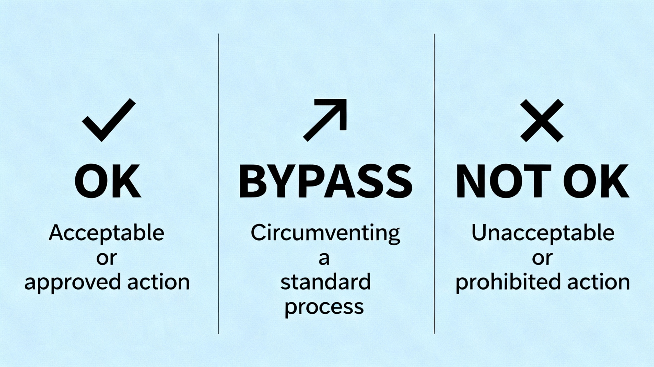
What OK, BYPASS, and NOT OK Really Mean
The front panel tells you a great deal before you ever grab a meter. The 3500/42 uses an OK LED to indicate monitor and transducer health, a BYPASS LED to show whether alarms are active, and a TX/RX LED for communications behavior. The operation and maintenance guidance published via ManualsLib for the 3500/42 maps ON, OFF, and flashing patterns around roughly 1 Hz, 2 Hz, and 5 Hz to distinct conditions and corrective actions. Most proximity alarm investigations begin here, not at the bearings.
The most common patterns point to a handful of actionable states. A not configured or in calibration/configuration state requires exiting the mode or pushing a correct configuration to the module. A generic monitor error directs you to consult the System Event List to determine severity and root cause before you swap hardware. A transducer that has stopped providing a valid signal pushes you to check both the System Event List and the Alarm Event List to understand which channel is at fault and whether the issue is intermittent. A timed OK channel defeat can make the module appear not OK since the last reset; in that case, pressing the RESET button on the Rack Interface Module clears the latched condition once the underlying issue is resolved. And if the monitor is not operating correctly and not executing alarming functions, that is a replace-now situation rather than a wait-and-see.
The BYPASS LED is simple but consequential. Off means alarming is enabled; on means some or all alarming is disabled. After maintenance, it is easy to leave a channel or the whole monitor in a bypassed state. Before declaring victory on any repair, confirm BYPASS is cleared so protection is truly restored.
LED Patterns and What They Tell You
| LED behavior or state | Likely meaning | What to do first |
| Not configured or in configuration/calibration mode indicated by the LED pattern | Configuration is missing or the module is in a special mode | Exit the mode or reconfigure the monitor using the rack software |
| OK LED and pattern indicating a monitor error | An internal monitor issue is present | Review the System Event List to determine severity and specifics |
| LEDs indicate normal operation | The module is operating correctly | Record-as-found, no action required beyond verification |
| OK logic indicates a transducer is not providing a valid signal | Sensor, wiring, or proximitor path problem | Check the System Event and Alarm Event Lists to pinpoint the channel and condition |
| Condition shows timed OK channel defeat since last reset | A timed defeat is latched | Press the RESET button on the Rack Interface Module after confirming the condition is resolved |
| Condition shows monitor not operating correctly and not executing alarms | The monitor cannot protect | Replace the monitor and reload the verified configuration |
This mapping is summarized from the 3500/42 operation and maintenance guidance made available on ManualsLib. Always cross-check the exact LED cadence and combination against the current manual for your firmware revision.
Interpreting ŌĆ£Error CodesŌĆØ Through the Event Lists
The 3500 platform expresses most fault conditions through event entries rather than human-readable code numbers. For proximity monitor alarms, the System Event List and the Alarm Event List are your primary diagnostics. Manuals and service notes from Baker Hughes and Bently Nevada emphasize reviewing these lists before hardware replacement. The lists tell you whether the fault was an instrument trip, a transducer not OK, a configuration mode entry, a timed defeat, or a monitor error. They also provide the timing and sequence, which helps distinguish a true channel failure from a momentary wiring or grounding disturbance.
A practical habit is to snapshot the event lists before you touch anything. After you apply a fix, clear the lists, then observe whether the same sequence reappears. That before-and-after comparison is often the difference between a one-and-done repair and a lingering nuisance fault that comes back on night shift.
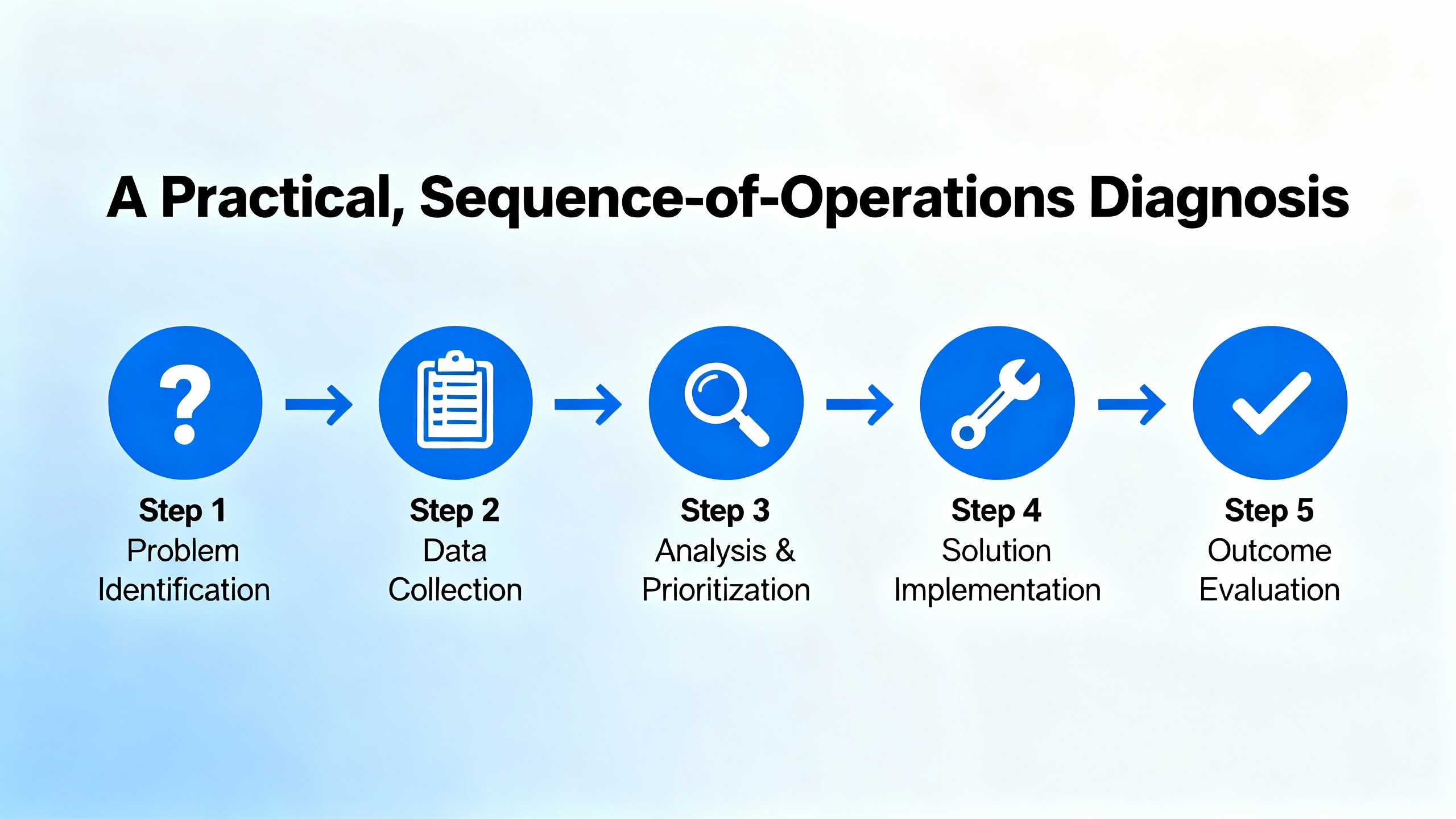
A Practical, SequenceŌĆæofŌĆæOperations Diagnosis
Start with safety and governance. The 3300-era troubleshooting manual reminds us that calibration and wiring work temporarily removes machine protection. DeŌĆæenergize where required, use proper PPE, and follow lockout/tagout when you open panels or move probes. Treat a rack like any live panel that sits next to rotating equipment and high voltage. Plan the steps before you begin, because in proximity systems a small change in gap or grounding can snowball into a spurious trip if you are casual.
Confirm the module state. Look at the 3500/42 front panel. If LEDs indicate a configuration or calibration state, address that first. If OK is off or flashing and the event list mentions a specific channel, correlate that channel to the physical transducer loop and proceed there. If the BYPASS LED is on, understand whether the bypass was deliberate for maintenance or accidental, and document any changes before clearing it.
Check the configuration. Use the rack configuration software to confirm the module type and channel setup match the installed transducer system. Proximitor scale factors, extension cable lengths, and intended measurement type must align with the actual hardware. If a module was replaced recently, verify that the correct configuration was loaded. Bently NevadaŌĆÖs documentation set that includes the Rack Configuration and Utilities Guide (129777ŌĆæ01) and the field wiring diagrams (130432ŌĆæ01) exists for this reason. Mismatches between configured and installed components are a frequent root cause of ŌĆ£mysteryŌĆØ alarms.
Validate the transducer loop. For proximity channels, check that the probe, extension cable, and Proximitor are the correct model family and length combination, and that connectors are clean, tight, and free of moisture or corrosion. If the system supports reading the gap voltage, use it. The Baker Hughes condition monitoring guidance notes that probe gap voltage is a quick way to spot a seating, wiring, or driver issue without disassembling the bearing. If the gap voltage is not within the manufacturerŌĆÖs stated range for your probe system, you have a transducer path issue long before you have a machine fault. For seismic channels, use accelerometer bias voltage or equivalent health readings in the same way.
Eliminate grounding and noise problems. A surprising fraction of erratic proximity alarms come from ground loops and poor shielding. Ubest AutomationŌĆÖs field notes stress singleŌĆæpoint grounding and isolation where needed. In practice this means ensuring shields are grounded at one end in accordance with the wiring diagram, rack chassis grounds are clean and tight, and there is no second, unintended return path via conduit or tray. If you recently connected the monitor to a new DCS or gateway, recheck that the added path did not create a ground loop.
Rule out external display contradictions. If the HMI or DCS is flagging a proximity alarm that the 3500/42 does not corroborate, confirm how the data is ingested. In older Mark V era projects, HMIs were often displayŌĆæonly and occasionally were fed by buffered analog signals with different scaling and zeroing than the rack, which can cause discrepancies. Control.com practitioners have described misaligned thrust references that showed ŌĆ£alarmŌĆØ on an HMI but normal behavior in the protection rack. If needed, align zero settings and methods, and when safe, perform a controlled shaft movement test to reconcile readings across systems. That sort of hydraulic ram test is a decisive way to prove which instrument is telling the truth.
Document, reset, and reŌĆæobserve. After you correct the underlying condition, press the RESET button on the Rack Interface Module to clear any latched timed defeats, confirm the BYPASS LED is off, and then watch the event and alarm lists. If the fault returns on a cadence, that timing often points to a power or communications disturbance rather than a sensor failure.
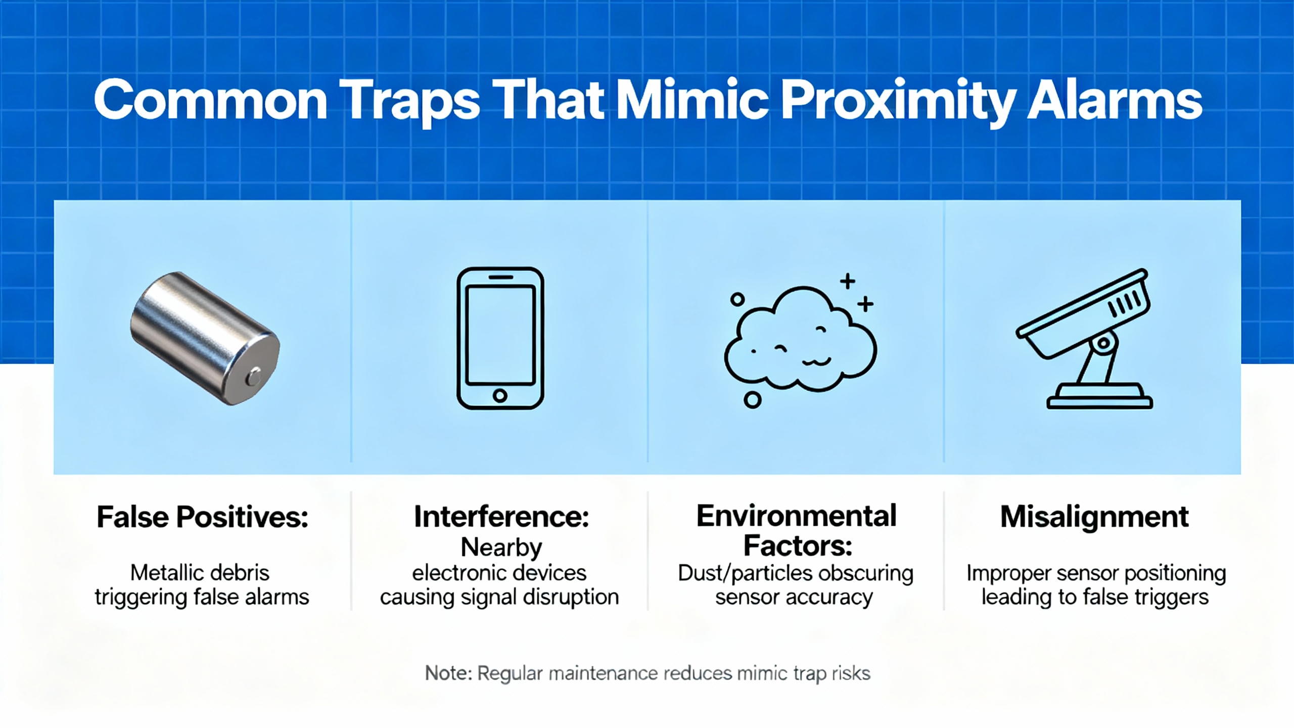
Common Traps That Mimic Proximity Alarms
Thrust versus radial confusion is the classic trap. Both use nonŌĆæcontact probes, but they answer different questions. Treat thrust as its own measurement with its own reference. Do not expect a thrust alarm to correlate with a radial vibration channel on the same bearing.
Communication illusions are the modern trap. On multiŌĆætrain upgrades, data can disappear at the HMI even while the 3500 rack and channels are OK. A widely discussed example on Control.com involved a 3500/92 EGD gateway feeding GE Mark VIe HMIs. The HMIs lost vibration data while process parameters remained fine. The gateway reported a NOT OK status in the configurator even though modules and channels were OK, and the OK LED on one gateway flickered. The fix path there ran through EGD configuration hygiene, not sensor replacement. Verifying producer and consumer IPs, unique exchange IDs, update rates, lengths, and UDP ports, and checking for duplicate IDs across units restored stable communications. When proximity alarms appear to come and go with a regular interval or unitŌĆætoŌĆæunit propagation, your problem may be in the network path rather than the bearing.
Setting Alarm Levels That Help Instead of Hurt
Factory defaults and standards are a safe starting point for protection, but they are not the end of the story. Baker Hughes has written about alarm strategy for condition monitoring in ORBIT, highlighting that standards and OEM recommendations tend to emphasize overall levels and acceptance testing. Protection alarms from the 3500/42 should be conservative enough to trip when a machine is at risk. Condition monitoring alarms in the historian can be much more nuanced, using spectral bands and learning to catch early degradation without overwhelming operators.
Manual settings still matter. Experienced analysts often set initial thresholds while watching live data for a specific machine, as the Baker Hughes guidance notes. BaselineŌĆæbased schemes, where you set alarm levels relative to the first good reading, are useful for fast deployment. If you use the example from the ORBIT article that describes an increment of 2.0 mm/s over baseline, convert that to roughly 0.08 in/s and make sure the machine was truly healthy during that initial run. LearningŌĆæbased methods, whether statistical or AIŌĆæassisted, can deliver earlier warnings by fusing process and operational context with vibration, but they still require clear governance so operators see only the alarms they need to act on.
Operator visibility is different from analyst visibility. Control rooms need simple, unambiguous annunciation at high and danger levels, while reliability teams need early warnings and band alarms to plan work. Modern software supports multiple levels per trend so both groups get what they need. Decide who has the right to change alarm levels and enforce that discipline. Nothing erodes trust faster than dueling edits on the same measurement.

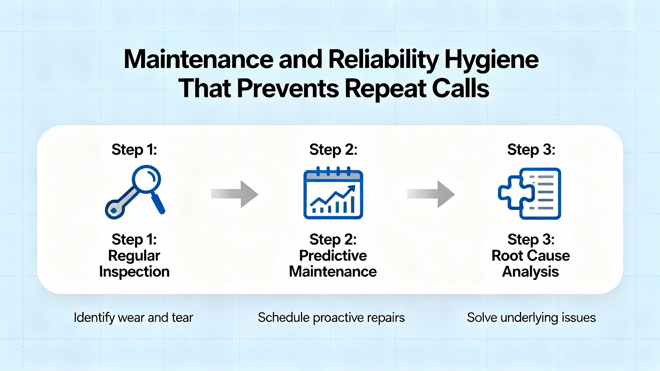
Maintenance and Reliability Hygiene That Prevents Repeat Calls
Power matters. The Ubest Automation troubleshooting guide calls out voltage fluctuations and power module faults as culprits behind unexpected rack behavior. If you are chasing intermittent proximity alarms and event lists show periodic reinitialization without an obvious cause, put a meter on the rack input, examine the power supply modules for telltale LED indications, and correct any upstream variability.
Connections age. Racks live in heat and dust, and bearings sweat oil vapor. Cleaning module edges, reseating connectors with care, and inspecting Proximitor and extension cable connectors reduce intermittent contact issues that masquerade as machine faults. Doing this work quarterly on critical trains is a cheap way to avoid nuisance alarms.
Grounding is a choice you make every day. Once you have fixed a ground loop in one panel, you can prevent five more by documenting the singleŌĆæpoint strategy and repeating it on every new expansion. Standardize your bonding and shield terminations across MCCs, control rooms, and skid panels.
Configurations drift. Back up the rack configuration after every change and before any firmware update. Keep at least one spare 3500/42 with a knownŌĆægood configuration image ready for swap tests. If a channel alarm follows the module when you swap, replace the module. If it stays with the slot or channel, the problem is in wiring or the transducer path.
Communications deserve the same rigor. If your proximity alarms appear and disappear with HMI data availability, align your DCS or gateway configurations with the same discipline you apply to protection racks. In the 3500/92 EGD case that Control.com discussed, the fix was not a reŌĆægapped probe; it was clean exchange mapping and network hygiene.
When Replacement Is the Answer
No one wants to replace a monitor without certainty. Fortunately, the 3500/42 tells you when that is the right call. The operation and maintenance guidance makes it explicit that a monitor not operating correctly and not executing alarming functions must be replaced. Before you pull it, capture the configuration, note firmware, confirm the transducer path is healthy, and record event lists. After replacement, reload the verified configuration, verify OK status, and execute a controlled functional check. This preserves traceability and prevents future misinterpretations.
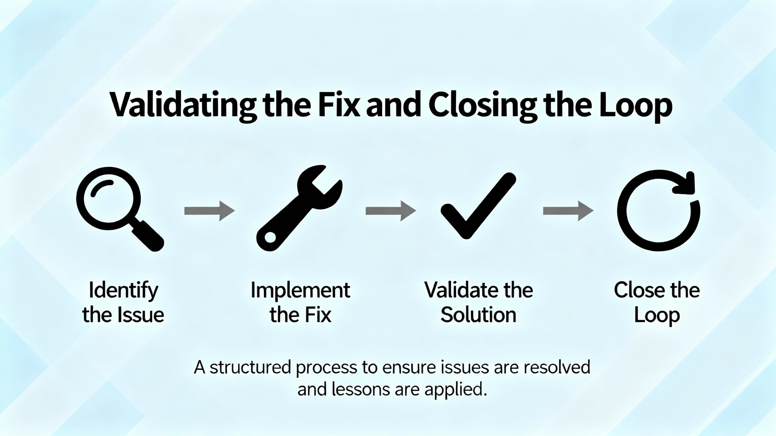
Validating the Fix and Closing the Loop
Once the alarm condition is resolved, clear any timed OK defeats with the RESET button on the Rack Interface Module, confirm the BYPASS LED is off, and monitor live values. Document the asŌĆæleft gap or bias voltages, record the exact alarm setpoints, and note any configuration revision numbers. In your historian or condition monitoring software, preserve trends before, during, and after the event so you can tell whether the fix eliminated the symptom or merely reduced its frequency. If the alarm originated from a mismatch between displays or systems, record the agreedŌĆæupon zeroing and scaling methods on both sides to prevent a repeat.
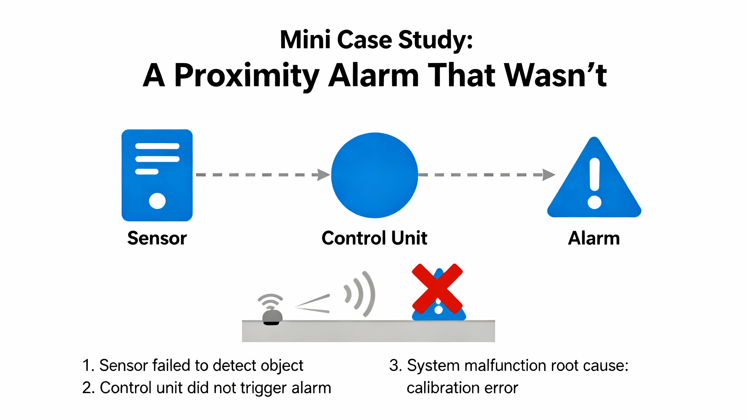
Mini Case Study: A Proximity Alarm That WasnŌĆÖt
A plant experienced a proximity alarm on an HMI that operators associated with a vibration problem. The 3500 rack showed OK, and event lists were quiet. Investigation revealed the HMI was visualizing a thrust reading with a different zero reference. The reliability team aligned the thrust zero on both systems and executed a controlled axial movement with a hydraulic ram to verify consistent readings. After alignment, both the HMI and the 3500 agreed, and the nuisance alarm disappeared for good. This pattern mirrors what seasoned engineers have described on Control.com, and it reinforces the value of understanding measurement intent before replacing hardware.
Safety, Compliance, and Ownership
Bently NevadaŌĆÖs historical manuals have always emphasized safety warnings and cautions for a reason. Calibration can temporarily remove protection. Exposed terminals can present shock and burn hazards. Always deŌĆæenergize where required, keep hands clear of rotating machinery, and follow site lockout/tagout procedures. At endŌĆæofŌĆælife, owners and operators are responsible for disposal consistent with applicable laws. Build these responsibilities into your maintenance and project procedures rather than treating them as afterthoughts.
Quick Reference Tables You Can Use On Shift
| Symptom at the 3500/42 | Most likely locus | First diagnostic move | Why it matters |
| OK LED off or flashing with event entries naming a channel | Transducer loop or configuration mismatch | Check gap or bias voltage and verify channel configuration matches hardware | Confirms instrument health before chasing a machine fault |
| BYPASS LED on after maintenance | Alarms disabled | Review maintenance notes, clear BYPASS, and verify protection | Prevents running unprotected after a repair |
| HMI shows proximity alarm but rack does not | Integration or scaling mismatch | Trace data path, align zero and scaling, and reconcile with a controlled test | Avoids replacing good sensors for a display problem |
| Alarm cadence near hourly and no machine symptoms | Network or power stability | Check rack input stability, gateway status, switch logs, and protocol mappings | Preserves trust in protection and reduces nuisance fatigue |
| Monitor error with no obvious field issue | Module fault | Read event list, reseat once, and if it recurs replace module and reload configuration | Changes only what needs changing, fast |
These tables summarize manual guidance and field experience discussed by Baker Hughes, ManualsLib copies of the monitor manual, and Control.com engineering threads. They should be customized to your plantŌĆÖs device models and firmware revisions.
FAQ
What is the fastest nonintrusive check for a suspect proximity channel on the 3500/42? The fastest checks are reading the gap voltage in the rack software and reviewing the System Event List and Alarm Event List. If gap voltage is out of the expected range for your probe system, correct the transducer loop first.
Can I rely on an HMI alone to judge proximity alarms? Use the HMI for visibility, but rely on the 3500 rack and its event lists for protection truth. If there is a discrepancy, trace the data path and reconcile zeroing and scaling before swapping hardware.
How should I set alarm levels for early detection without overwhelming operations? Set conservative protection thresholds in the rack for trips, then use your condition monitoring system for more nuanced alarms. Start with manual or baseline-based thresholds and progress to learning-based methods as you gain data maturity, as discussed by Baker Hughes in its ORBIT content.
Closing Perspective
Well-behaved proximity protection is a reliability multiplier for your entire power system. Diagnose with the monitorŌĆÖs own evidence first, align measurement intent across systems, and harden the mundane basics like power, grounding, and configuration control. Do that consistently and your UPS, inverters, and switchgear will see far fewer preventable trips from the rotating assets upstream.

References
| Publisher or source | Relevance |
| Baker Hughes Bently Nevada ORBIT | Alarm level strategy, nuisance alarm triage, and condition monitoring practices |
| ManualsLib copy of Bently Nevada 3500/42 O&M | LED fault behaviors, BYPASS meaning, timed OK defeat, and RESET usage |
| Control.com engineering forums | Thrust versus vibration measurement alignment and 3500/92 EGD communication failure patterns with Mark VIe |
| Ubest Automation | Field troubleshooting patterns for power, communications, grounding, module swap tests, and firmware hygiene |
| Bently Nevada manuals set (Rack Installation and Maintenance 129766ŌĆæ01; Rack Configuration and Utilities 129777ŌĆæ01; Computer Hardware and Software 128158ŌĆæ01; Field Wiring 130432ŌĆæ01) | Configuration, wiring, validation utilities, and communications setup guidance |
| Historical Bently Nevada troubleshooting manuals | Safety warnings and cautions regarding calibration, exposure, and temporary loss of protection |
- https://prod.ials.sas.ac.uk/zpenetrated/391B10E/ttransportc/917B514E61/bently+nevada+1701+user+manual.pdf
- https://do-server1.sfs.uwm.edu/dl/%5E7345XP7249/slide/8340XP0/bently+nevada+1701+user+manual.pdf
- https://assetmanagementprofessionals.org/discussion/bently-rack-protection-and-the-not-ok-signal
- https://www.machineryanalysis.org/post/troubleshooting-orbit-analysis-using-bently-nevada-system-1-10170139?trail=30
- https://studylib.net/doc/27017185/bently-nevada-3500-proximitor
- http://www.mchip.net/browse/u14BBH/242498/bently_nevada_3500-operating-manual.pdf
- https://www.artisantg.com/info/Baker_Hughes_Bently_Nevada_3300_20_12_01_02_00_00_Manual_2020519201751.pdf?srsltid=AfmBOoqVWgUBBcKabj2xDfNfJRqTYnIkRCmWcTRt-7zGrjkDsSsxsamy
- https://www.bakerhughes.com/bently-nevada/support-services
- https://www.manualslib.com/manual/1867177/Bently-Nevada-Proximitor-3500-42.html?page=200
- https://www.scribd.com/document/329110291/3500-42-Proximitor-Seismic-Monitor-Module-Op-Maintenance-Man


 Videos
 News
News Applications


Leave Your Comment