The Bently Nevada 3500 platform is the backbone of machinery protection in many refineries, gas processing plants, and power stations. At the heart of that platform, the 3500/22M Transient Data Interface (TDI) acts as the rackŌĆÖs brain for configuration and data movement, bridging the protection system and your condition monitoring tools. When a rack goes quiet on the network, the Rack OK annunciation changes state, or a channel looks wrong, you can lose confidence fast. This guide distills field-proven diagnostic steps for the 3500/22M, backed by the vendor datasheet and operations manuals as well as industry troubleshooting experience, so you can localize faults quickly and restore reliable monitoring.
What the 3500/22M TDI Actually Does
The TDI is the rackŌĆÖs primary interface to configuration and data acquisition. It connects to a laptop over USB for local work and to the plant network over Ethernet for continuous connectivity to supervisory software such as System 1. The TDI stores and manages the rack configuration, synchronizes modules, and relays statuses. According to the vendorŌĆÖs product datasheet from Baker Hughes, it provides four front-panel indicators for health and status, supports a hardware keylock and password security for configuration control, and hosts a DIP switch for rack address management when multiple racks are networked. The Rack OK relay resides in the TDIŌĆÖs I/O module and is driven by numerous module-level and rack-level conditions; per the datasheet, it is intended for annunciation and not for use in a machinery auto-shutdown circuit.
On purpose, the TDI is not in the critical protection path. That design means you can often work on communications and configuration without compromising trips and alarm functions. It also means some faults you see on the TDI are secondary effects of module, sensor, or wiring issues elsewhere in the rack.
Definitions You Will Use In This Guide
A few definitions matter when you triage 3500 events. The Rack OK relay is a form-C relay in the TDI I/O module driven by NOT OK conditions within the TDI and other rack modules; it is a global health annunciator rather than a shutdown-grade contact. Trip Multiply is a control that raises alarm thresholds under known transient conditions such as startup; the TDI supports front-panel and remote inputs for Trip Multiply and Reset, and an Alarm Inhibit input at the I/O module. A Keyphasor is a once-per-revolution reference used for speed and phase tracking; it synchronizes rotor-related diagnostics. A Proximitor is the eddy-current probe driver that powers a non-contact proximity probe and converts the RF return to a DC bias and dynamic signal proportional to shaft motion. GAP voltage is the DC output at the Proximitor that represents probe-to-target distance; in typical Bently Nevada proximity systems, the output becomes less negative as the gap increases, with a nominal sensitivity around 200 mV per mil over the linear range as described by instrumentation practice notes.
Safety, Preparation, and Data Capture
Before touching the rack, look, listen, and document. Note the state of every front-panel LED on the TDI and power supplies, gather screenshots of any operator displays, and record exact wording of alarms. If your site uses System 1 or an equivalent historian, bookmark the time of the event and export a snapshot of status and strip charts. Many 3500 modules support hot swapping; however, follow your siteŌĆÖs lockout/tagout and hazards analysis and confirm with operations before you pull a card. Have a known-good patch cord, a USB cable, and a grounded wrist strap at hand. When you do open the cabinet, check environmental and mechanical basics first, such as door gaskets, purge/ventilation where applicable, cable strain relief, and signs of condensation or oil ingress.
Drawing on multiple site interventions, capturing evidence up front saves time later. When the transient condition clears, an overlooked indicator or a change in Trip Multiply state can be hard to reconstruct. Securing a baseline makes it easier to prove true resolution later.

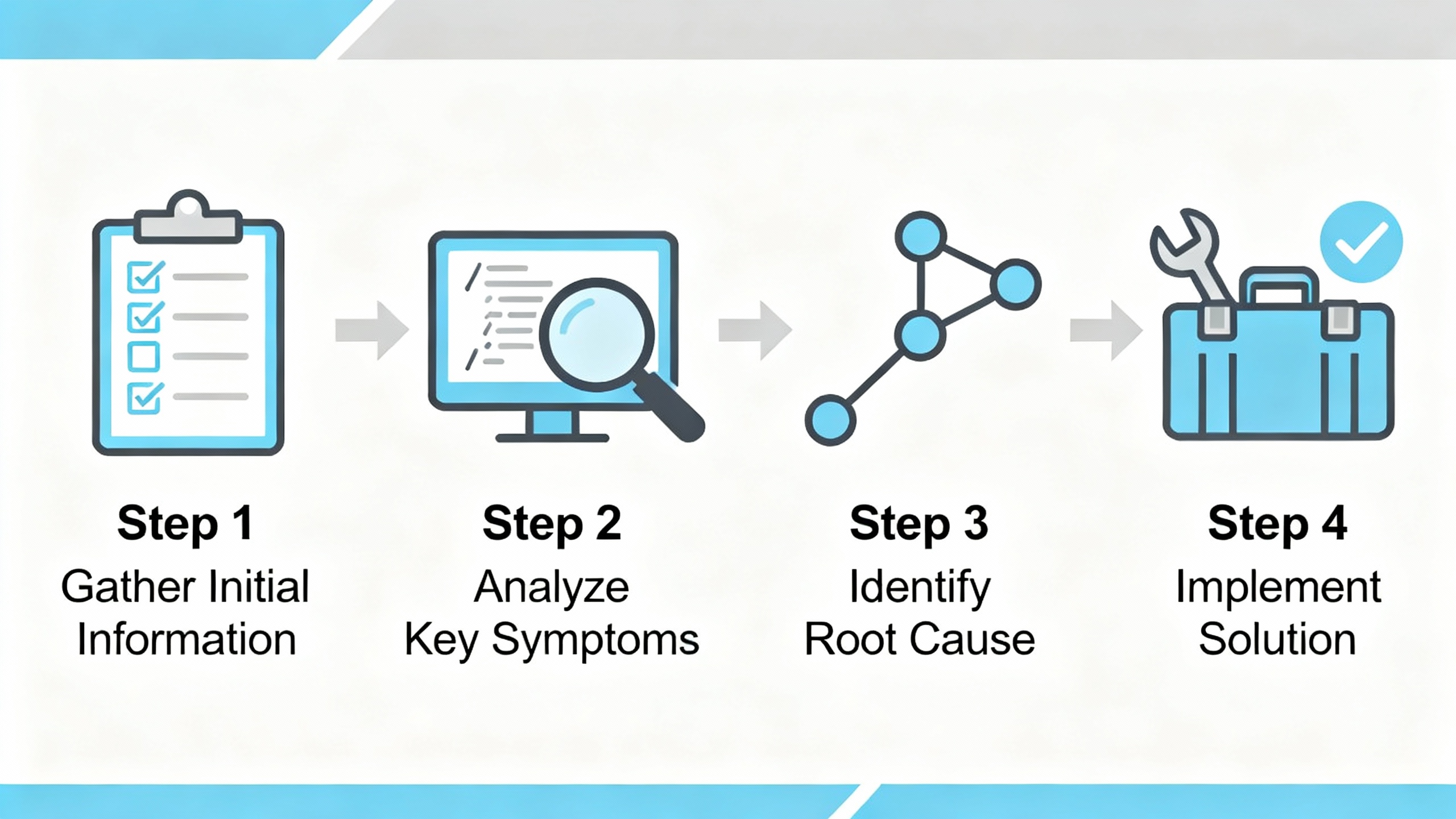
A Step-By-Step Diagnostic Flow That Works
Start at the rack, not the workstation. The 3500/15 power supplies feed every module, including the TDI. When both redundant supplies are installed, the lower is primary and the upper is backup, and either can power the entire rack. Confirm both supply modules show a healthy indication and that the rack is not running on a marginal backup. A single loose terminal on the incoming source can create strange, intermittent symptoms across the rack.
Move next to the 3500/22M. The OK indicator should be lit, indicating healthy operation of the TDI and its I/O module. The TX/RX indicator should be flashing at a rate that tracks communications among rack modules. If TX/RX is dark while the OK remains on, suspect a communications path issue, not a module hardware failure. In the field, I frequently find a misconfigured switch port, a failed patch cable, or a speed/duplex negotiation mismatch at the cabinet uplink. For local isolation, connect via the TDIŌĆÖs front-panel USB port and confirm that you can retrieve rack configuration and statuses; when USB works and Ethernet does not, the problem is almost always outside the TDI.
When the configuration/status indicator reports a mismatch, compare the stored configuration to the physical module layout. The rackŌĆÖs keylock and software passwords are designed to prevent unauthorized changes; verify the keylock position and security settings before attempting edits. A mismatched or unconfigured module, a module moved to a new slot, or an I/O change without a corresponding configuration update can all produce a configuration alarm. Resolve the mismatch by updating the configuration to the present hardware or, if the hardware was changed unintentionally, by returning hardware to the last-known-good state.
If the Rack OK annunciation drops to NOT OK, treat it as a starting point rather than a verdict. The datasheet is explicit that dozens of conditions can drive this relay, and it is not intended for shutdown logic. Use module front-panel LEDs and buffered outputs to identify which module is asserting NOT OK. In practice, a single channel with a sensor fault can pull Rack OK down even when all dynamic measurements look normal at a glance.
When communications intermittency is suspected by operations or trending software, verify address settings and cabling at the cabinet first. When multiple racks are networked, the TDIŌĆÖs DIP switch assigns a unique rack address; conflicts here can manifest as unpredictable data availability. From recent case histories, replacing an aging switch and updating firmware at the control network layer restored stable data flow for a 3500-to-PLC link that had been dropping in and out. If your historian or DCS stopped receiving values after a configuration change, double-check protocol settings and IP parameters in the configuration software; an off-by-one address block or a typo in an IP can make an otherwise healthy rack appear ŌĆ£silent.ŌĆØ
Finally, if you still cannot reach the rack over Ethernet but USB access is fine, try a cold power cycle only if permitted by plant procedures and after ensuring protection functions will not be compromised. Because the TDI is outside the critical protection path, a controlled reboot to clear a transient communication fault is often acceptable; confirm with operations.
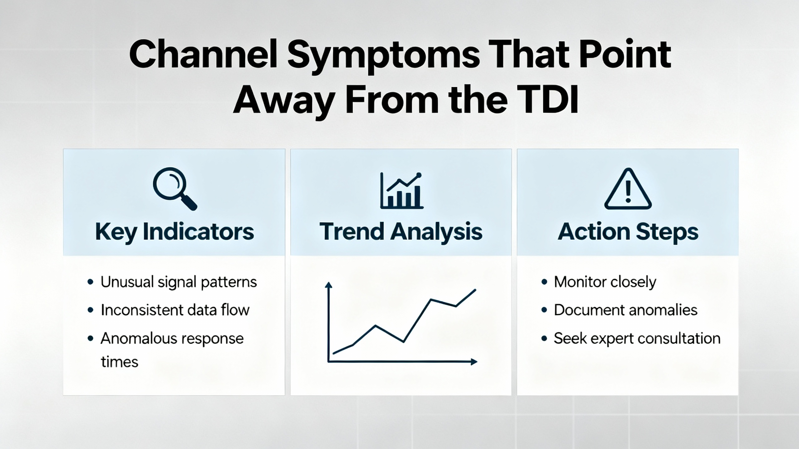
Channel Symptoms That Point Away From the TDI
When the rack communicates properly but one or more channels look wrong, turn your attention to the transducers and monitors. In Bently Nevada proximity systems, static GAP voltage and dynamic sensitivity are reliable quick screens of health. A common, healthy installed GAP is roughly ŌłÆ8 to ŌłÆ12 VDC, and the systemŌĆÖs sensitivity is nominally 200 mV per mil across its linear region. When the GAP is near the rail, the channel may be gapped too tight or too loose, or the probe system could be damaged. Where practical, use a micrometer fixture to move the probe in controlled steps and verify linear response; a straight-line relationship from roughly 10 to 80 mil indicates healthy operation. If the output flattens, jumps, or becomes irregular, you are likely looking at a damaged probe, a broken conductor in the extension cable, or electromagnetic interference. Simple electrical checks help: healthy probes often measure a few ohms across the coil and extension cable continuity falls in a small tens of ohms range; compare to your specific modelŌĆÖs specs.
When a once-per-rev reference signal is missing or erratic, examine the Keyphasor probe alignment and target condition. Excessive runout, poor reflectivity or magnetism of the target, insufficient clearance, or a damaged cable can all interrupt a clean pulse. After any sensor replacement, confirm mechanical positioning against the manual and retake acceptance data to anchor your baseline.
When several vibration channels show inconsistent sensitivity or bias after maintenance, pay attention to what changed. Vendor guidance stresses that a proximity probe system is tuned for a specific probe, extension cable, and driver at a calibrated total length. Using the wrong cable length shifts calibration and reduces linear range, leading to false alarms and missed faults. In troubleshooting, I ask a technician to check part numbers end to end and verify exact cable lengths before exploring more exotic causes.
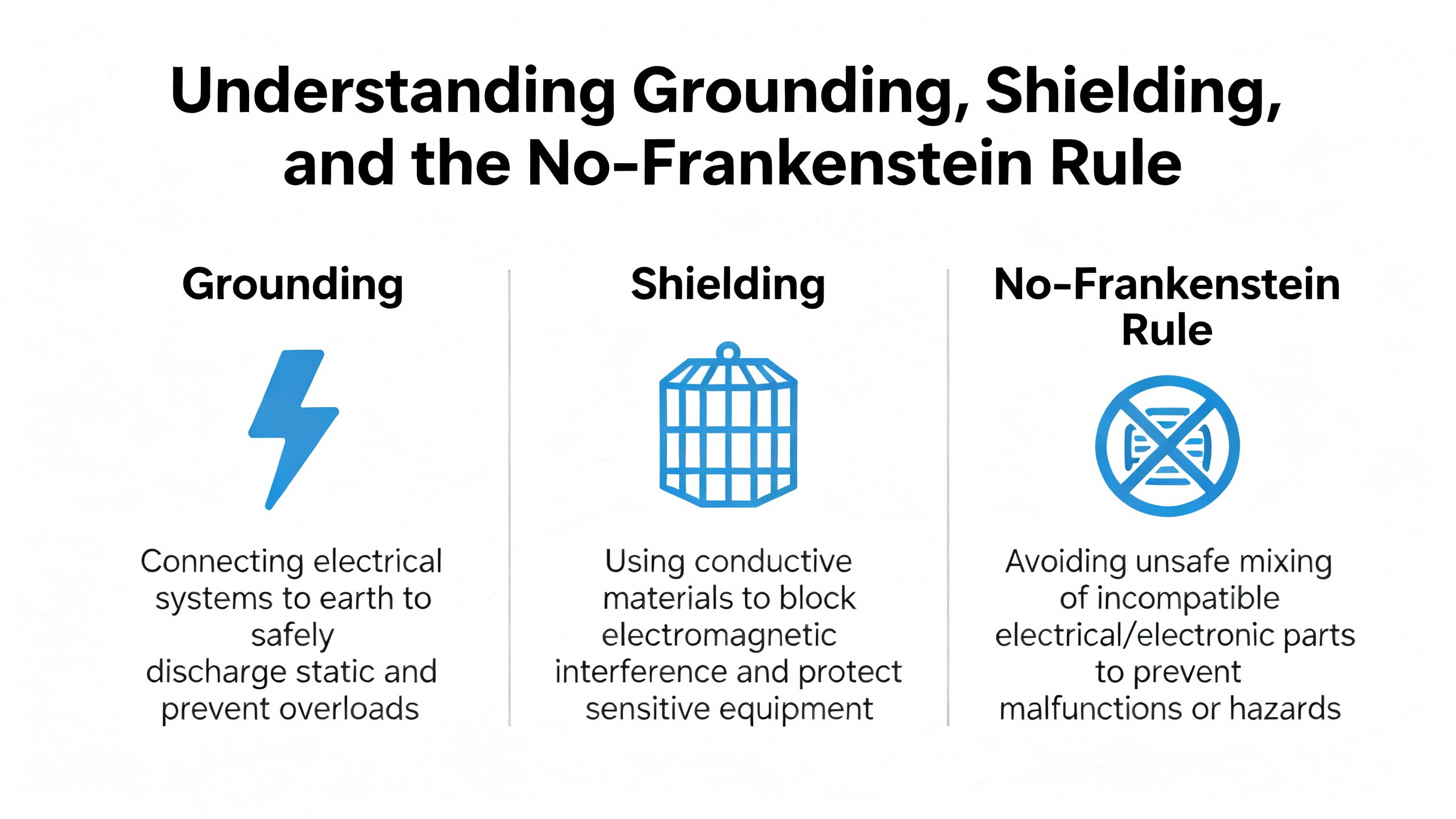
Grounding, Shielding, and the NoŌĆæFrankenstein Rule
Grounding and shielding hygiene often separates quiet, reliable systems from noisy ones. Single-point (star) grounding with shields terminated at the designated location prevents ground loops that inject noise and cause spurious readings. Keep signal cables segregated from power conductors and provide strain relief at the sensor and junction box to prevent motion-induced noise and connector fatigue.
Just as important, avoid mixing parts from different eddy-current systems. Baker Hughes has documented that so-called mixed or ŌĆ£FrankensteinŌĆØ systemsŌĆöusing a competitorŌĆÖs driver with Bently Nevada probes and cablesŌĆöproduce non-linear response and scale errors. In tests, the mixed 9-meter system attenuated vibration readings by roughly a quarter at larger gaps, with incremental scale factor falling well below the intended 200 mV per mil. In the other direction, a mixed 5-meter setup overstated vibration. Gap voltage may look normal while the machine is idle, masking the error until the machine runs. In thrust protection, wrong scaling can be catastrophic. The practical upshot is straightforward: keep a matched set from a single manufacturer and verify total length exactly.
Interpreting FrontŌĆæPanel Indicators Fast
The TDIŌĆÖs front panel tells a story if you know what to look for. The OK indicator conveys overall TDI health, and the TX/RX indicator shows internal communications activity. The Trip Multiply indicator confirms when alarm thresholds have been raised for transients. The configuration/status indicator flags configuration errors or mismatches between stored and physical rack configuration. When these indications are captured during a fault, they narrow your search and help you decide whether to reach for a USB cable, a patch cord, or a spare module.
| Indicator | Normal behavior | Abnormal symptom | Likely cause(s) | What to do |
| OK | Lit steadily | Off or cycling | TDI/I/O fault or power instability | Verify power supply health; reseat module; use USB to check TDI status; replace if NOT OK persists |
| TX/RX | Flashing regularly | Dark or erratic | Network issue or internal comms fault | Try USB; check Ethernet cabling and switch port; confirm address and protocol; consider controlled reboot |
| Trip Multiply | Off in steady-state | On during startup or transient | Intentional threshold raise | Confirm it is not left engaged after transient; verify remote input circuit behavior |
| Configuration/Status | Off in steady-state | Lit or blinking | Unconfigured module, mismatch, or security condition | Inspect keylock/passwords; compare stored vs physical layout; update or revert configuration |
These indicator meanings distill what is published by the vendor in the system datasheet and operations manuals and align well with what technicians encounter during commissioning and maintenance.
Quick Electrical Benchmarks for Proximity Probe Diagnostics
When vibration channels are suspect, a few numbers get you oriented. The supply to a Proximitor typically sits in the negative teens to negative twenties volts DC, and the healthy installed GAP voltage often falls between approximately ŌłÆ8 and ŌłÆ12 VDC. Many common systems exhibit sensitivity of about 200 mV per mil over a broad linear range that spans several dozen mils, with negative polarity becoming less negative as the gap increases. Probe coils often read a handful of ohms, and extension cables show low, consistent resistances when checked end to end. These are practical guideposts, not absolutes; verify against your probe and driver part numbers.
| Check | Typical value | What it means |
| Proximitor supply | About ŌłÆ18 to ŌłÆ24 VDC | Healthy driver supply for many models; check vendor specs |
| Installed GAP voltage | About ŌłÆ8 to ŌłÆ12 VDC | Reasonable gap at rest; rails or drift indicate gapping or hardware issues |
| Sensitivity | About 200 mV per mil | Expected slope in the linear range; major deviation implies calibration or hardware issue |
| Probe coil resistance | About 5ŌĆō9 ╬® | Very low or very high values indicate damage |
| Extension cable continuity | About low tens of ohms | Open or highly variable values suggest cable damage |
These values and procedures are consistent with common eddy-current probe testing practice described by instrumentation references used on turbine supervisory control and condition monitoring work.
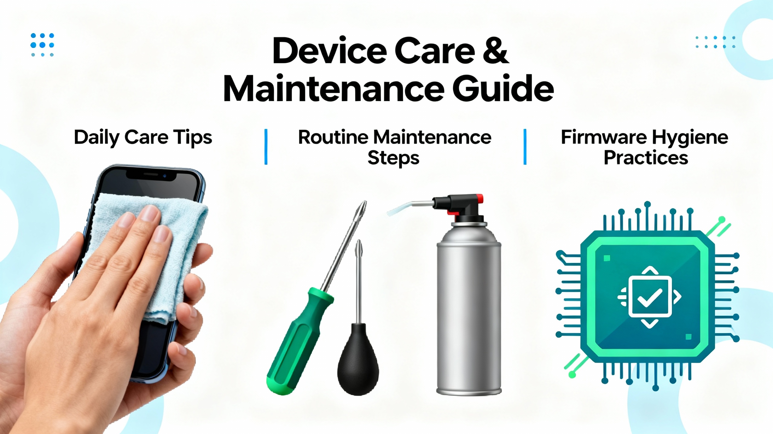
Care, Maintenance, and Firmware Hygiene
Discipline prevents most surprises. A monthly visual check of modules, connectors, and cable strain relief catches looseness, contamination, and mechanical damage before they become outages. A quarterly verification that channels still hit expected bias and sensitivity removes drift before it impacts trips. Annual calibration and configuration reviews are a good default; for critical assets, shorten these intervals. Keep firmware current in line with plant policies to avoid known defects and to maintain protocol compatibility. Trend both the machineŌĆÖs overall vibration and the probe bias voltage, and set reasonable alarms on unexpected drift or saturation so you see a deteriorating probe before an outage forces you to.
Pros and Cons of the 3500/22M as the Diagnostic Hub
The 3500/22MŌĆÖs design brings several advantages during troubleshooting. Because it is outside the protection path, you can work on communications and configuration without undermining the machineŌĆÖs safety envelope. A front-panel USB port and Ethernet make it easy to connect locally and remotely. The dedicated indicators for OK, communications activity, Trip Multiply, and configuration provide fast context when the phone rings.
There are tradeoffs. If your plant relies exclusively on network visibility, a minor Ethernet fault can look like a big problem to a control room. A configuration mismatch will light a status indicator even when the rack is protecting the machine correctly, prompting unnecessary changes if you do not check the physical module layout first. The Rack OK relay is an annunciator; treating it as if it were a shutdown contact leads to poor trip logic and false expectations. These are not flaws so much as reminders to use the TDI for what it does best: manage and surface configuration and data, not enforce trips.

Buying and Spares Advice From the Field
When you buy or stock a 3500/22M, ensure you procure the correct I/O module variant for your installation and review revision compatibility with your plantŌĆÖs condition monitoring software. Keep at least one spare TDI for critical units, and maintain redundancy on power supplies so the rack does not depend on a single supply. If your plant standardizes on a Proximitor family, you can cover a wide set of needs with a small number of spares; vendor guidance emphasizes full interchangeability within a family, which reduces downtime and cost.
For proximity probe systems, insist on genuine, matched sets and exact cable lengths. Avoid mixing components from different manufacturers and never substitute cable lengths; vendor testing has shown non-linear response and scale errors that can effectively shift alarm and trip thresholds. In inventory, label cable lengths prominently and segregate by length and family, and document total system length per channel in the rack configuration.

RealŌĆæWorld Cases and What They Teach
A gas processing plant fought intermittent loss of data from a 3500 rack into a programmable controller. After chasing phantom module errors, technicians replaced an aging network switch and updated firmware; connectivity stabilized and the false alarms vanished. The lesson is that communications faults are often outside the rack and that the TDIŌĆÖs USB access is your best friend for ruling in or out the rack itself.
In another case, a compressor showed repeated vibration alarms accompanied by inconsistent GAP voltages. Inspection found a damaged proximity probe cable; replacing it restored normal operation. That scenario illustrates the value of confirming bias and sensitivity against expected values rather than assuming the monitor or TDI is at fault.
During a startup on a compressor, a site reported a lost Keyphasor and abnormal X and Y radial probe behavior. After changes to instrumentation, the Keyphasor normalized while the X and Y probes still looked wrong. That sequence often points to a matched-set problem, incorrect gapping, or disturbance to the probe cabling rather than a TDI fault. Mechanical checks of probe alignment, target condition, and cable integrity typically resolve the remaining anomalies.

Frequently Asked Questions
Can I replace the 3500/22M while the rack is powered?
The 3500 platform supports hot swapping of modules, and the TDI is not in the critical protection path. Many plants replace or reseat a TDI without shutting down the machine. Always follow site procedures, coordinate with operations, and confirm that the work will not interfere with protection functions or network change controls.
Why is the Rack OK annunciation NOT OK when the machine seems healthy?
The Rack OK relay aggregates many conditions, including module configuration mismatches and transducer NOT OK statuses. It is an annunciator designed to get your attention, not a shutdown device. Check module LEDs to identify which card is asserting NOT OK, review configuration vs hardware, and confirm that any sensor faults or wiring issues are addressed.
The TX/RX indicator is dark, but I can connect with USB. What does that mean?
That combination is consistent with a network or addressing issue rather than a failed TDI. Inspect the Ethernet patch cord and switch port, verify protocol and IP settings in the configuration, and confirm that the rack address is unique. A controlled reboot is sometimes justified after you have ruled out cabling and switch faults.
How can I quickly tell if a proximity channel is healthy?
A quick screen is bias and slope. A healthy installed GAP is typically around the negative ten volt range, and the dynamic sensitivity is generally near 200 mV per mil over a broad linear region. If the bias is near a rail or the slope is non-linear in a micrometer test, suspect gapping, cable damage, or a failing probe before blaming the monitors or TDI.
Is it acceptable to mix a different manufacturerŌĆÖs eddyŌĆæcurrent driver with Bently Nevada probes and cables?
Mixing parts from different systems is not advisable. Vendor testing has shown non-linear response and scaling errors in mixed systems that can attenuate or exaggerate vibration measurements and effectively shift alarm and trip thresholds. The safest approach is a fully matched set from one manufacturer and exact, documented cable lengths.
Takeaway
Start with the rackŌĆÖs fundamentals, read the TDIŌĆÖs indicators, and use the USB port to separate network problems from rack problems. Confirm that the rack configuration matches the hardware, and treat Rack OK as an annunciation to be investigated rather than a trip device to be trusted. When channels look odd, prove probe health with bias and slope, and keep your probe systems matched and at the correct length to avoid subtle scaling errors. The 3500/22M is a powerful diagnostic hub precisely because it is not in the protection path; use it to see clearly, document rigorously, and return your asset to a state where the protection system and the maintenance organization both trust the data.
References
Baker Hughes Bently Nevada 3500 System Datasheet; Bently Nevada 3500/22M Operation and Maintenance Manual; Automation & Control Engineering Forum; NextGenŌĆæPLC Limited; Ubest Automation Limited; Baker Hughes Orbit article on proximity probe system interchangeability; AutomationForum proximity probe functional testing; Power Gear X Automation Limited; ManualsLib training material for Siemens Bently Nevada 3500 Proximitor.
- https://www.academia.edu/43778168/3500_System_Product_Datasheet_Bently_Nevada_Asset_Condition_Monitoring_Description
- https://do-server1.sfs.uwm.edu/dl/2028094OV1/ebook/14266VO/bently_nevada_3500__42__vibration-monitoring__system__manual.pdf
- https://assetmanagementprofessionals.org/discussion/frame-sensors-tripped-due-to-lightning
- https://www.machineryanalysis.org/post/commtest-vb7-issue-10644342
- https://studylib.net/doc/27017185/bently-nevada-3500-proximitor
- https://www.artisantg.com/info/GE_Bently_Nevada_3500_33_01_Manual_20184271141.pdf?srsltid=AfmBOoqXa9jS4eSNEfIYYXCizmSqfwAyAcqGOGgnm0aHyN_4intgTZ1n
- https://automationforum.co/functional-testing-of-bently-nevada-vibration-probes/
- https://www.nexgen-plc.com/bently-nevada-3500-system-troubleshooting/
- https://www.powergearx.com/bently-nevada-piezo-velocity-sensor-installation-10-mistakes-to-avoid-for-reliable-industrial-automation/
- https://www.manualslib.com/manual/1953082/Siemens-Bently-Nevada-3500-Proximitor.html


 Videos
 News
News Applications


Leave Your Comment