When a Bently Nevada 3500 rack goes dark or stops talking to your control system, you are not just losing a vibration trend. You are potentially operating highŌĆæenergy rotating equipment without the protection layer that the 3500 platform was installed to provide. As a powerŌĆæsystem specialist working with reliability teams, I see the same pattern over and over: the root of ŌĆ£rack not workingŌĆØ issues usually lives in two places, rack power and rack communications, with configuration and maintenance practices sitting quietly in the background.
Technical guides from Actech Parts, troubleshooting articles from Ubest Automation, and field discussions on engineering forums converge on this point. Power supply faults, unstable rack power, bad communication paths, and configuration errors are the recurring themes behind most 3500 incidents. In this article, I will walk through how the 3500 rack sits inside your power and communication chain, what typically fails, and how to approach troubleshooting and redesign with a powerŌĆæandŌĆæreliability mindset rather than a narrow ŌĆ£instrument glitchŌĆØ mentality.
How the Bently Nevada 3500 Rack Fits into Your Protection System
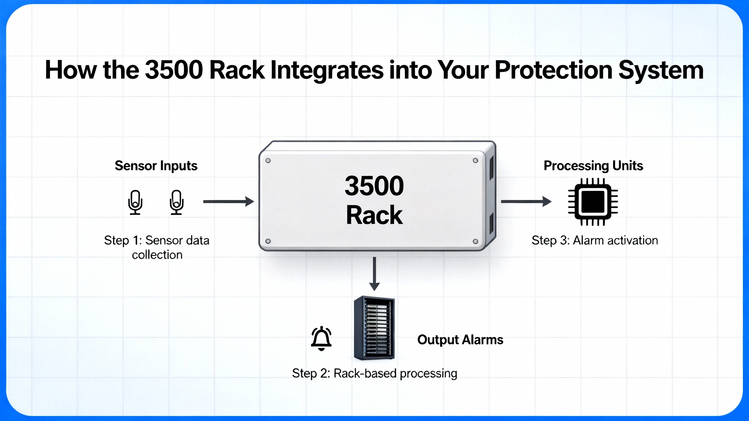
The Bently Nevada 3500 is a modular machinery protection and conditionŌĆæmonitoring system designed for highŌĆæreliability rotating equipment. It aggregates signals from proximity probes, seismic transducers, and other sensors, processes them in real time, and drives alarm and trip logic to protect critical assets. A guide reviewed by a senior industrial automation engineer emphasizes that its core advantages are enhanced machinery protection, flexible and scalable system design, and reduced downtime via redundancy features, combined with comprehensive monitoring across critical machine parameters.
Inside the rack, several subsystems matter when you are troubleshooting power or communication problems. Individual monitor modules such as the 3500/42 Proximitor/Seismic Monitor accept signals from eddyŌĆæcurrent proximity transducers and seismic sensors and convert them into measurements like shaft vibration, casing vibration, and shaft position. These modules apply scaling, filtering, and alarm logic, typically with configurable Alert and Danger levels, and they interface with relay modules that can trip or annunciate when limits are exceeded.
At the rack level, the Transient Data Interface or Rack Interface Module, often referred to as the TDI or RIM, manages sensor inputs, internal rack communications, and communications out to external systems. In normal operation, an OK relay on the TDI/RIM signals module health to the DCS or similar host system. When that relay drops, plant operators see alarms even if the machine itself is mechanically healthy.
A small but important detail from operating documentation is the role of rack indicators and switches. The rack uses a CONFIG OK LED to confirm that the modules in the rack form a complete and correct configuration after power is applied. A reset switch can clear latched alarms and reset timed OK or channel defeat indications; it also stops a fiveŌĆæhertz blinking configuration LED and performs the same function as the Rack Reset contact on the Rack Interface I/O Module. A key switch in RUN or PROGRAM position prevents or allows configuration changes; removing the physical key lets you lock the rack in one of these states to prevent unauthorized modifications.
When any of these pieces lose power or become unstable, the visible symptom is often simply ŌĆ£rack not workingŌĆØ or ŌĆ£no vibration data at the DCS.ŌĆØ Underneath, the failure mode is almost always tied to power quality, power continuity, or the communication path that carries data out of the rack.
To frame the discussion, the following table summarizes the subsystems that matter most for power and communication issues and the kinds of symptoms they produce.
| Subsystem | Primary function | Typical symptoms when it misbehaves |
| Rack power input and supplies | Deliver stable power into the 3500 rack and its modules | Complete rack shutdowns, modules losing power, powerŌĆæsupply LEDs in fault state |
| TDI/RIM and OK relay | Handle sensor inputs and rack communications, signal health to DCS | Intermittent module reboots, OK relay drops, transient DCS alarms |
| Monitor modules (e.g., 3500/42) | Process vibration/position signals and generate alarms | Channel alarms, nonŌĆæresponding module, inconsistent readings |
| Communication links to DCS/PLC | Carry data between 3500 and host systems | No data updates, frequent communication failures or drops |
Once you see the rack as part of a broader power and communications ecosystem rather than as an isolated box, the troubleshooting path becomes clearer and more systematic.
Why Power Problems Are the First Suspect When the Rack Is ŌĆ£DeadŌĆØ
Technical guidance from Actech Parts and Ubest Automation both highlight power supply problems as a common cause of unexpected Bently Nevada 3500 rack issues. The causes they describe are straightforward but often overlooked during rushed field checks: power source interruption, faulty power supply modules, and improper installation or wiring. The recommended first actions are equally basic but decisive: check source connections, verify rack input voltage, inspect the power supply modules themselves, and replace any unit that shows a red LED or other fault indicator, then compare the installation against official guidelines.
This sounds obvious, yet in practice reliability teams frequently jump straight to software or sensor diagnostics and spend hours on configuration screens while a failing power module in the rack is quietly pulling the system down.
Loss of Rack Input Power
A troubleshooting article on common 3500 faults underscores that power problems are a leading cause of unexpected rack shutdowns. The first question is whether the rack is actually being supplied with correct input power from the upstream distribution. That means checking breakers and fuses in the supply path, verifying that any upstream UPS or powerŌĆæprotection equipment is online, and confirming that the voltage at the rack input meets the expected value. If your rack is fed through rackŌĆæmount power distribution units rather than directly from a control panel, those PDUs must also be considered part of the power chain.
Guidance on reliable rack power distribution from sources such as Synaccess and Clark Wire makes one critical point: safe power distribution starts with accurate capacity planning and an understanding that continuous loads should not exceed about eighty percent of a PDUŌĆÖs maximum current rating according to NEC guidance. Even when a PDU is not visibly overloaded, the combination of continuous load and redundancy requirements can leave you with less margin than you think.
Faulty Power Supply Modules
Actech Parts notes that power supply failure itself is a common issue in the 3500 platform. Power supplies are not immortal. Thermal stress, age, contamination, and upstream disturbances can all damage internal components. The Ubest Automation troubleshooting article recommends inspecting the rackŌĆÖs power supply modules and replacing any unit showing a red fault indicator. This is not a guess; the power supply modules are designed to tell you when they are not healthy.
If you swap in a knownŌĆægood supply and the symptom disappears, you have your answer. If the problem persists, then the issue may be upstream or in the rack backplane. At that point, deeper diagnostics or OEM support become necessary.
Installation and Configuration Problems
Not every ŌĆ£noŌĆæpowerŌĆØ symptom is a purely electrical failure. ActechŌĆÖs guide lists improper installation as one of the typical root causes behind powerŌĆærelated problems, and operating documentation clarifies how the 3500 rack uses configuration status to indicate whether its internal module set is coherent. After power is applied, the CONFIG OK LED should indicate that the rack contains a complete and correct configuration. If that LED never turns on, the documentation advises contacting a Bently Nevada representative rather than improvising, because the underlying issue may be an incomplete module set, a configuration mismatch, or another condition that is not solved by cycling power.
Configuration errors that do not prevent a rack from powering but do cause alarms or misbehavior are a separate class. UbestŌĆÖs article on common 3500 faults points to incorrect setpoints, alarm values, or other parameters as sources of operational problems. Best practice in those situations is to back up the current configuration, carefully verify each change, and reload a knownŌĆægood configuration if inconsistencies appear, rather than layering adŌĆæhoc edits.
Overloaded or Misdesigned Rack Power Distribution
In modern plants, Bently Nevada racks are rarely standing alone. They are typically installed in racks or enclosures that also hold servers, communication switches, and other electronics. Power distribution guides from Synaccess and Clark Wire show how easy it is to misjudge loading in such environments.
An example from the Synaccess guide explains that in a dualŌĆæPDU redundant setup using twentyŌĆæampere PDUs, you might see thirteen amperes on each PDU under normal conditions. That looks safe because thirteen amperes is only about sixtyŌĆæfive percent of the rating. However, if one power path fails, the remaining PDU is suddenly asked to carry the full twentyŌĆæsix amperes, which exceeds its rating and trips upstream protection, shutting down everything on that rack. The same guide recommends two complementary budgeting approaches. In what it calls a simple rule, under normal operation each PDU should be kept below about forty percent of its rating so that, after a failure, the surviving PDU does not exceed eighty percent of its rating. A more detailed method is to ensure that the total rack load stays below about eighty percent of each PDUŌĆÖs rating so that either PDU can safely handle the entire load if one source is lost.
When your Bently rack is fed through such redundant PDUs, an apparently harmless incremental addition of load elsewhere in the rack can eat the margin that is supposed to protect your monitoring system. A rack that ŌĆ£randomly goes deadŌĆØ during power events may simply be revealing an underlying design that violated these power budgeting principles.
A Structured Power Troubleshooting Workflow
Approaching a 3500 rack problem as a powerŌĆæsystem issue rather than a mysterious instrumentation failure changes the sequence of checks and, in my experience, shortens downtime. The following workflow is consistent with the recommendations in Actech and Ubest technical material, combined with rackŌĆæpower best practices from Synaccess, Clark Wire, and rackŌĆæmanagement experts.
Begin with safety. RackŌĆælevel AC power can be lethal, and utility, UPS, and generator sources can all be present. Before opening enclosures or touching wiring, follow your siteŌĆÖs lockoutŌĆætagout procedures and verify absence of voltage where required. No diagnostic insight is worth an incident.
Once safe access is established, verify upstream sources. Confirm that the feeder supplying the rack is energized and correctly protected. If the rack is powered via a UPS, check that the UPS is online, not in a bypass or fault condition, and that its output matches expected levels. If generators are part of your critical power scheme, confirm that they have not been recently tested or taken out of service in a way that could explain observed events.
Next, examine PDUs and local power distribution. For rackŌĆæmount PDUs, check any local current metering and note whether total load is approaching design limits. Metered PDUs, as described in the Synaccess guide, display total current consumption and can give early warning of an overloaded path. Where smart PDUs are installed, use their remote metering and alert features to review current and historical load on each circuit. Look for segments where the current spikes near maximum during plant events.
Then move to the rack itself. Inspect the Bently power supply modules for status indicators. Ubest Automation advises replacing any supply showing a red LED, and the Actech guide lists module replacement as a standard corrective action for power supply failure. Pay attention both to supply health and to whether the rest of the rack appears energized. If the rack is completely dark despite healthy upstream power, that points to a supply, backplane, or internal connection problem.
Check configuration and status indicators. Confirm whether the CONFIG OK LED is lit after powerŌĆæup. If it is not, and the rack never reaches a declared good configuration, heed the documentation guidance to involve Bently Nevada or qualified specialists rather than attempting arbitrary resets. If the LED is lit but other anomalies persist, configuration errors may still be involved, and a configuration backup and detailed review are appropriate.
Review event logs and correlate with power events. An engineering discussion about a 3500 installation described unexplained TDI/RIM module reboot events that occurred twice over three days. Each event triggered a DCS alarm via the TDI OK relay, lasting about fiftyŌĆætwo seconds, and the system event log showed entries with identifiers such as 320, 340, and 341 corresponding to module reboot sequences. By the time maintenance personnel arrived, indicators were normal and no latched faults were present. The thread noted that such intermittent TDI/RIM reboots are often associated with unstable rack power, loose backplane connections, firmware anomalies, or transient disturbances in field wiring, although those causes were not confirmed for that specific case.
The recommended practice from that discussion is instructive: review detailed event logs around the reboot identifiers and correlate their timestamps with plant power quality data, switching operations, or process disturbances. If reboots consistently coincide with transfer operations, generator starts, or other power events, the working hypothesis should shift toward power quality or distribution. Complement that log review with physical checks of module seating and backplane contacts, and verify that TDI and RIM modules are running vendorŌĆærecommended firmware revisions.
Finally, consider grounding and noise. UbestŌĆÖs troubleshooting guide highlights ground loops as a less obvious but real source of signal problems and instability. Ground loops, defined as unwanted multiple grounding paths, introduce electrical noise that distorts measurement signals. The recommended mitigation is to use isolated signal conditioners where needed and to design grounding so that all grounds terminate at a single point, particularly for vibration channels. This is not just a ŌĆ£nice to haveŌĆØ for data quality; excessive noise and erratic readings can cause unnecessary alarms or mask real problems, and severe disturbances may even contribute to module misbehavior.
If you work through this sequence and the rack power behavior remains unexplained, the issue has likely moved beyond basic troubleshooting and into the realm of deeper hardware or firmware problems that warrant OEM or specialist support.
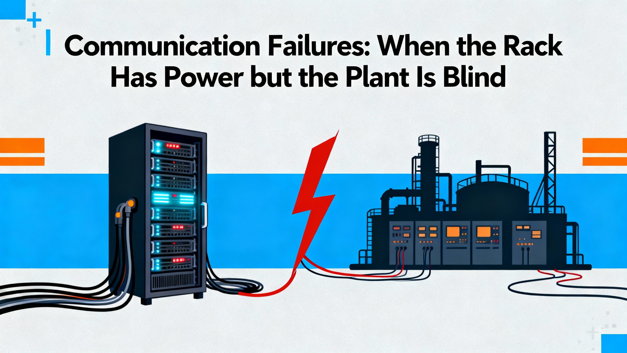
Communication Failures: When the Rack Has Power but the Plant Is Blind
A powered rack that is silently collecting data but not delivering it to your DCS or PLC is another highŌĆærisk scenario. The machinery is still being monitored locally, but operators are effectively blind to its condition unless they stand at the cabinet. Both the Actech guide and Ubest Automation article emphasize that communication failures are a frequent complaint and that they usually trace back to a few recurring causes.
The symptoms of communication failure vary. Some plants see complete loss of data at the control system. Others observe intermittent ŌĆ£communication failureŌĆØ alarms that clear themselves. In the TDI/RIM reboot case mentioned earlier, each reboot of the module activated the OK relay and generated a DCS alarm for roughly fiftyŌĆætwo seconds, then everything appeared normal. In another realŌĆæworld case described by Ubest, a power plant suffered repeated communication drops between a 3500 system and an AllenŌĆæBradley PLC. Eventually, replacing a faulty network switch and updating firmware restored stable data flow.
ActechŌĆÖs 3500 guide notes that communication failure often stems from faulty communication cables, incorrect configuration settings, or module failure. Their recommended actions are to inspect and, if necessary, replace communication cables, review and correct configuration parameters, and test or replace suspect modules. UbestŌĆÖs troubleshooting content adds practical detail: when data is not reaching the DCS or PLC, technicians should verify network cables and connectors, ensure that communication protocols and IP addresses match between the 3500 configuration software and the host system, and swap modules to see whether a problem follows a particular unit.
From a powerŌĆæsystem perspective, it is important not to treat communication issues as entirely separate from power. Network switches, media converters, and other devices in the path depend on their own power supplies and can be subject to the same loading, redundancy, and power quality pitfalls as the 3500 rack itself. In the plant case where a switch replacement solved repeated communication drops, the root cause lived in the network device rather than the 3500 modules.
A systematic approach to communication troubleshooting therefore mirrors the power workflow. Start by confirming that each device in the communication path has stable power and correct status. Inspect physical media for damage, loose connectors, and improper routing. Ubest recommends using a multimeter on sensors; for network segments, the equivalent is link lights, port statistics, and simple connectivity tests where available. Then move on to configuration verification, using the 3500 manuals to interpret alarm codes and configuration screens, as Ubest stresses that alarm indications are coded and that each type corresponds to a specific fault.
If communication problems are intermittent and coincide with power events or TDI/RIM reboots, treat them as a coupled powerŌĆæandŌĆæcommunication problem and follow the log correlation approach described previously, rather than trying to ŌĆ£fixŌĆØ the network in isolation.
When Power and Communication Problems Interact
The most frustrating incidents are those where power and communication faults overlap. A TDI module that reboots due to marginal rack power will drop its OK relay, trigger alarms in the DCS, and may briefly interrupt communications. A network switch powered from an overloaded PDU may reset during current peaks, cutting data flow while leaving the 3500 rack itself powered. Poor grounding and noisy supply rails can corrupt both analog measurements and digital communication.
The field discussion on intermittent TDI/RIM reboots provides a clear example of how these interactions manifest. Event logs showed specific reboot identifiers and the OK relay behavior produced transient alarms, but by the time technicians arrived, all hardware indicators were normal. Recommended checks included verifying rack power supply stability, inspecting TDI and RIM seating and backplane contacts, and confirming firmware revisions. These are all interventions at the intersection of power integrity, hardware connectivity, and module software.
At the same time, the Synaccess powerŌĆædistribution guide reminds us that a dualŌĆæPDU redundant design can hide overload risks that only appear during a failure. If your communication infrastructure and your 3500 rack share the same redundant PDUs and the design does not follow the fortyŌĆæpercent and eightyŌĆæpercent budgeting methods, a single failure can take down both protection and communication hardware in one stroke.
This is why, when investigating intermittent or coupled failures, it is crucial to review logs from the 3500 rack, power distribution, and network devices side by side. Look for timeŌĆæaligned patterns. If event identifiers associated with TDI reboots line up with breaker operations, UPS transfers, or PDU alarms, then the linchpin is almost certainly in the power chain. If network switch logs show resets at the same times that communication to the 3500 is lost, but the rack event log is quiet, the focus should shift to the network devices and their power feeds.
Designing a More Robust Power and Communication Environment
Once the immediate fire is out, reliability teams usually ask what they can change so they do not see the same problem again next quarter. Here the broader literature on serverŌĆærack power and rack management is surprisingly relevant to industrial monitoring systems.
PowerŌĆæredundant rack guides from Synaccess describe a typical setup that uses the utility grid as a primary source, with an uninterruptible power supply and backup generator as secondary sources. In that architecture, two rack PDUs feed equipment with redundant internal power supplies. The PDUs may be basic metered units that simply report total current, smart PDUs that allow remote switching and perŌĆæoutlet metering, or dualŌĆæcircuit PDUs that pack two isolated circuits into one enclosure. Smart PDUs provide additional functions such as automatic notifications via email or SNMP when current thresholds are exceeded, defective device autoŌĆædetection, redundant network interfaces, and network watchdog features that help reduce operational costs.
The same sources emphasize that a fully redundant rack power setup aims for soŌĆæcalled twoŌĆæN redundancy, meaning that there are two independent power paths such that no single point of failure will interrupt operation. For true twoŌĆæN redundancy, each path and each component in the path must be able to support one hundred percent of the rack load by itself. That requirement, combined with the eightyŌĆæpercent continuous loading rule, drives the fortyŌĆæpercent and eightyŌĆæpercent budgeting methods discussed earlier.
Other rackŌĆæmanagement best practices from dataŌĆæcenter environments map nicely onto Bently Nevada cabinets. Articles on rack management and rack security highlight the value of keeping power and network cables on separate sides of a rack, using disciplined cable management and labeling to speed troubleshooting, and laying out equipment so that power distribution units do not block access to monitored hardware. KeysightŌĆÖs guidance on rackŌĆæmounting power supplies adds several important details: heavy power supplies should be mounted low to keep the center of gravity down, rack layouts must provide enough space for fans to intake and exhaust air, heatŌĆæsensitive instruments should be physically separated from hot, fanŌĆæcooled power supplies, and highŌĆæcurrent power cables should be routed away from lowŌĆælevel signal wiring to reduce electrical noise and magnetic interference.
For Bently Nevada racks, which process lowŌĆælevel vibration and position signals and depend on stable auxiliary communications, these layout and routing practices are not cosmetic. They directly influence the noise environment, thermal stress on modules, and ease of maintenance.
The table below summarizes design choices drawn from these references and how they support 3500 rack reliability.
| Design choice | Source of guidance | Benefit for Bently 3500 reliability |
| Dual PDUs with two independent sources | Synaccess powerŌĆæredundant rack guide | Maintains rack power if one source or PDU fails, avoiding unexpected shutdown |
| Power budgeting at about 40% normal load per PDU | Synaccess power budgeting methods | Prevents overload of remaining PDU during a powerŌĆæpath failure |
| Smart PDUs with metering and alerts | Synaccess smart PDU recommendations | Provides early warning of abnormal current draw and simplifies remote diagnostics |
| Separation of power and network cabling | RackŌĆæmanagement bestŌĆæpractice articles | Reduces interference and makes power and communication faults easier to trace |
| Proper airflow and weight distribution | Keysight powerŌĆæsupply rackŌĆæmount guidance | Avoids overheating modules and lowers risk of mechanical or thermal stress |
| Structured cable labeling and documentation | Rack management and security best practices | Speeds fault isolation and supports consistent maintenance across shifts |
In short, treat the power and communication environment around your Bently rack with the same engineering rigor you apply to your rotating equipment. A wellŌĆædesigned rack power and cable system is a reliability control, not just an aesthetic choice.
Maintenance Practices That Keep Racks Healthy
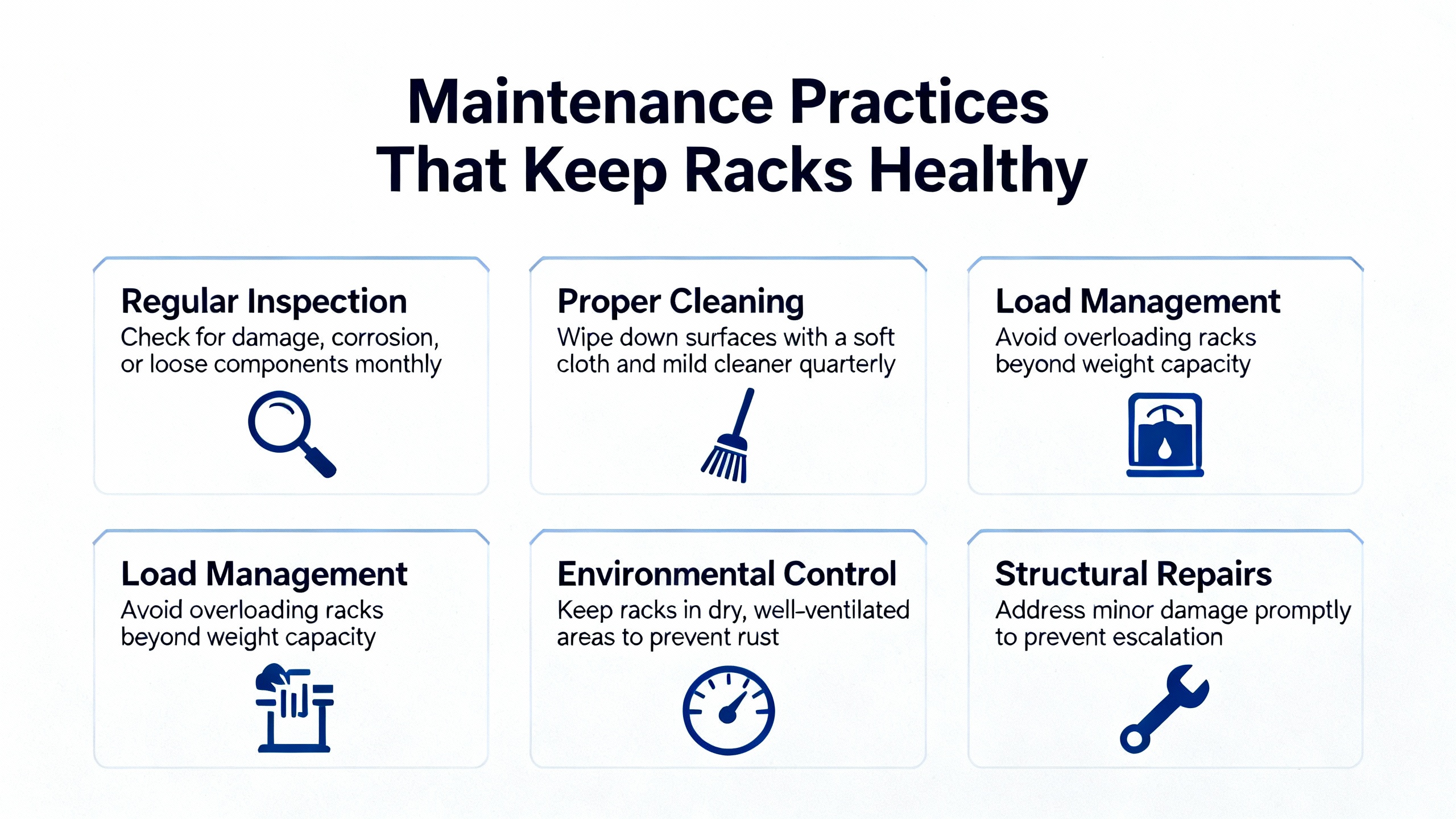
Even the best design will drift into trouble if it is not maintained. Ubest Automation emphasizes proactive maintenance for Bently Nevada 3500 systems, recommending regular cleaning of modules, checking connections on a defined schedule, and keeping firmware up to date. This is consistent with best practices from the 3500/42 monitor manual, which advises ongoing maintenance actions such as reviewing event and alarm logs, trending vibration and position levels against baselines, documenting configuration changes, and keeping configuration backups.
From a powerŌĆæsystem perspective, several maintenance activities pay outsized dividends. Periodic inspection of PDUs to ensure that their meters, alarms, and connections are functioning correctly helps you avoid creeping overload situations. Reviewing historical current trends, where smart PDUs or external meters provide them, can reveal slow growth in load that will eventually breach safe margins. Keeping accurate documentation of which devices are connected to which circuits, and updating that documentation when equipment is added or removed, prevents nasty surprises during fault isolation or emergency maintenance.
On the communication side, maintaining clean terminations, verifying cable condition, and checking that network devices such as switches and routers have current, vendorŌĆærecommended firmware reduces the probability of subtle communication glitches. The power plant case where replacing a network switch and updating firmware restored stable 3500ŌĆætoŌĆæPLC communications is a reminder that networking hardware ages and drifts just as power supplies and sensors do.
Configuration control is equally important. Ubest advises always backing up the 3500 configuration before making changes, carefully verifying new settings, and reloading a knownŌĆægood configuration when problems arise. The physical key switch on the rack that locks the configuration in RUN or PROGRAM mode is part of this discipline. Using it effectively, and storing the key in a controlled manner, prevents ŌĆ£driveŌĆæbyŌĆØ configuration edits that undermine reliability.
When to Engage OEM or Specialist Support
Even with solid troubleshooting and good maintenance, there are times when you should stop and call in help. The Actech guide expressly recommends consulting the full technical manual or contacting technical support for unresolved or complex system issues beyond the basic checks it describes. Bently NevadaŌĆÖs own Global Services organization presents its role in three phases. In a ŌĆ£get up and runningŌĆØ phase, service professionals help ensure that protection and monitoring systems are correctly designed, installed, and commissioned. In a ŌĆ£stay healthy and optimizedŌĆØ phase, they focus on keeping systems secure, compliant, and tuned as standards and technologies evolve. In a ŌĆ£maximize outcomesŌĆØ phase, they aim to turn monitoring data into actionable insights for operational decisionŌĆæmaking. With more than five hundred service professionals operating in over fifty countries, this is not a small or incidental support resource.
ThirdŌĆæparty specialists such as Ubest Automation also offer troubleshooting and genuine replacement parts for 3500 systems. Their guidance is clear: when power problems, communication failures, or module alarms persist despite reasonable inŌĆæhouse efforts, or when the system behavior is ambiguous enough that an incorrect action could compromise asset protection, it is time to involve experienced experts.
In my experience, the best reliability programs have a simple rule. Operations and maintenance teams perform wellŌĆædefined firstŌĆæline checks on power, communications, sensors, and configuration using procedures aligned with manufacturer guidance. If the problem is still present after those checks, they pivot quickly to OEM or specialist support rather than continuing to poke at a safetyŌĆæcritical system.
Brief FAQ
What is the first thing to check if a Bently Nevada 3500 rack appears dead?
Start at the power chain, not in the configuration software. Confirm that the upstream source is energized, that any UPS or generator in the path is operating correctly, and that the rack input voltage is present and within expected limits. Then inspect the rack power supply modules for fault indicators, as both Actech and Ubest highlight supply failure and input power problems as common causes of rack shutdowns.
Can I ignore intermittent TDI/RIM reboots if the rack always recovers?
Intermittent reboots with transient DCS alarms, such as those described in the controlŌĆæsystem forum discussion where TDI events lasted about fiftyŌĆætwo seconds and produced specific reboot identifiers, should be treated as signs of an incipient problem. Review event logs, correlate timestamps with plant power events, check rack power stability and module seating, and confirm firmware revisions. If reboots continue, engage Bently Nevada or qualified specialists; do not normalize repeated health relay drops as acceptable background noise.
How often should I review power loading and configuration on racks feeding protection systems?
There is no universal calendar interval, but combining guidance from rackŌĆæpower and 3500 troubleshooting sources, a quarterly review is a reasonable starting point. Use that review to inspect PDUs and rack power supplies, verify that total loads remain within the fortyŌĆæpercent and eightyŌĆæpercent budgeting guidelines where redundant PDUs are in use, check configurations against backups, and ensure firmware remains at vendorŌĆærecommended levels. Adjust the frequency based on how dynamic your environment is and how critical the protected assets are.
Reliable protection of rotating equipment depends as much on clean, wellŌĆæengineered power and communication infrastructure as it does on probes and algorithms. Treat your Bently Nevada 3500 rack as part of the plantŌĆÖs powerŌĆæprotection system, design and maintain its environment with the same rigor you apply to your UPS and PDUs, and many of the ŌĆ£rack not workingŌĆØ crises will quietly stop appearing.
References
- https://people.cs.vt.edu/huaicheng/p/fast18-failslow.pdf
- https://csng.cs.toronto.edu/publication_files/0000/0243/dsn2013-hpcfailures.pdf
- https://assetmanagementprofessionals.org/discussion/bentley-nevada-3500-tdi-3500-22m-problem
- https://mtsinfonet.org/server-rack-maintenance-best-practices-for-long-term-reliability-and-high-performance/
- https://www.hbs.net/blog/rack-management-best-practices
- https://studylib.net/doc/27017185/bently-nevada-3500-proximitor
- https://www.clarkwire.com/considerations-for-power-distribution-in-racks?srsltid=AfmBOooKlIhooRg5ZjOOtVSmKiK7oJAq8JhHGbLZxanpxgiK-hSLUWvy
- https://actechparts.com/bently-nevada-3500-complete-guide/
- https://www.artisantg.com/info/GE_Bently_Nevada_3500_42_Manual_20171113133924.pdf?srsltid=AfmBOooAIsnuZJOvVTXpbnvZKgUawJ5FnK7nfe-i-CEY76ZDDJl_ncZd
- https://www.bakerhughes.com/bently-nevada/support-services


 Videos
 News
News Applications


Leave Your Comment