Modern machinery protection is unforgiving of configuration mistakes. When a Bently Nevada 3500 rack flags a rack configuration fault or shows a ŌĆ£NOT OKŌĆØ state, the protection system is telling you that what the rack expects to see does not match what it actually sees in hardware, firmware, or communications. As a power system specialist who supports protection and reliability programs in plants that run doubleŌĆæconversion UPSs, inverters, and conditioned auxiliary power, I have learned that these faults are almost never random. They are the product of misalignment between configuration, infrastructure, and instrumentation. This article consolidates fieldŌĆæproven diagnostics from operations and maintenance practice and aligns them with guidance available from the manufacturer and experienced practitioners. It explains the meaning of rack configuration faults, what they look like in the 3500 ecosystem, why they appear, and how to resolve them safely and efficiently.
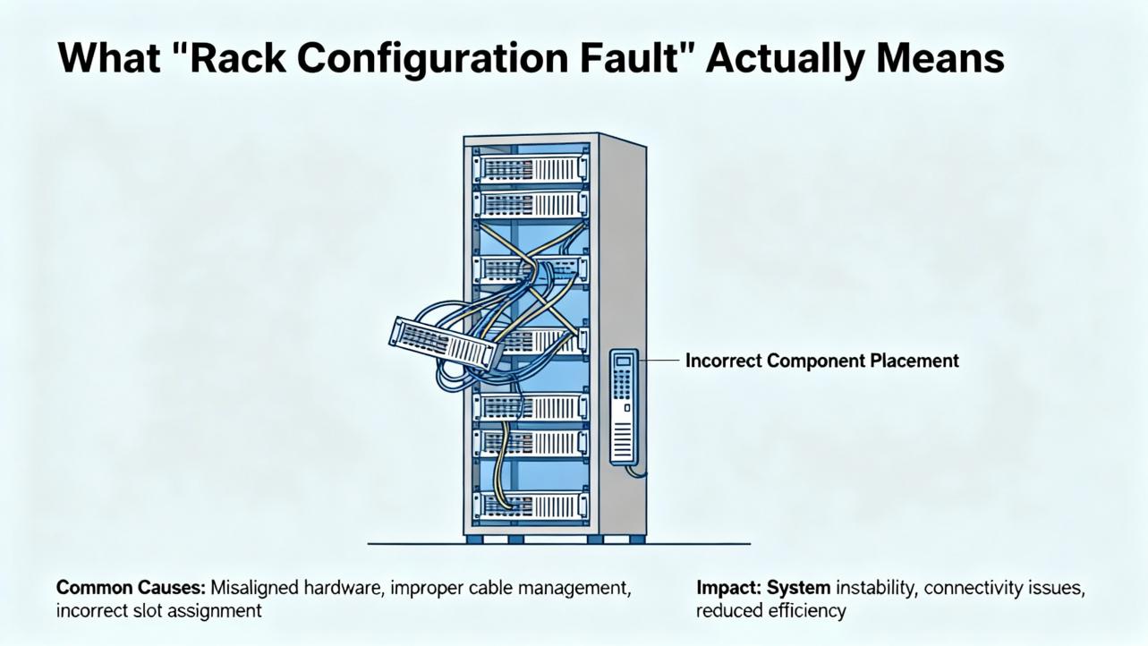
What ŌĆ£Rack Configuration FaultŌĆØ Actually Means
In the 3500 architecture, configuration is a contract between the rackŌĆÖs supervisory element and the installed modules, sensors, and communications gateways. The Transient Data Interface or Rack Interface Module supervises module health, validates the presence and identity of monitors, and manages loading and revision checks of configuration datasets. When the hardware present in a keyed slot, the firmware revision of a module, or the checksum of a loaded configuration does not match the dataset in the rackŌĆÖs nonvolatile memory or the expected keying, the supervisor raises a configuration error and the rack asserts a ŌĆ£NOT OKŌĆØ for the affected element. In practice, ŌĆ£rack configuration faultŌĆØ is an umbrella for several concrete conditions: missing or wrong module type in a keyed slot, firmware incompatibility with the resident configuration, corrupted or partial configuration load, disabled or mismatched channels, and communication mapping that references nonŌĆæexistent measurements. Authoritative descriptions of these mechanisms exist in the manufacturerŌĆÖs installation and maintenance manuals and are summarized in independent overviews such as the Actech Parts complete guide for the 3500 system published June 19, 2025, which emphasizes module identity, slotting, commissioning, and troubleshooting.
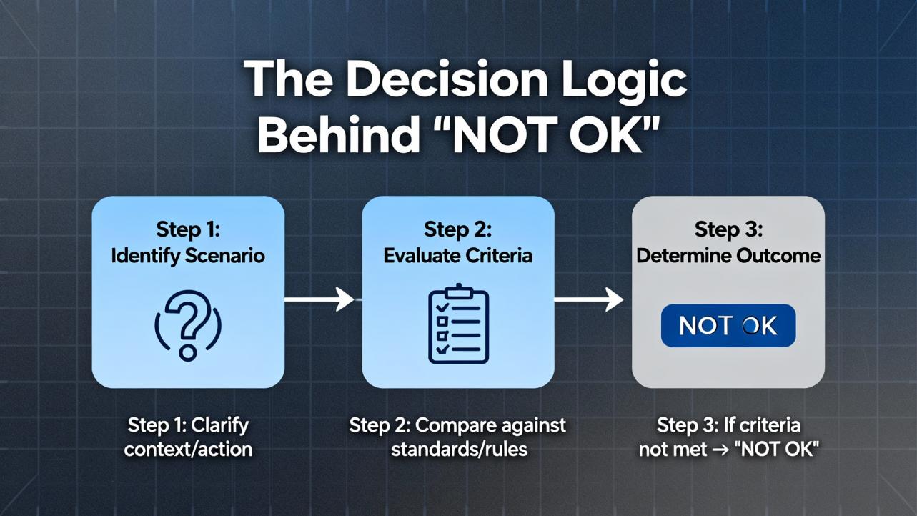
The Decision Logic Behind ŌĆ£NOT OKŌĆØ
The rackŌĆÖs supervisory logic does two things simultaneously. First, it verifies the integrity of the protection path by monitoring the ŌĆ£OKŌĆØ state of each module and the continuity and bias health of the associated transducers. Second, it validates the rackŌĆÖs internal configuration against physical reality. If the rack sees, for example, a fourŌĆæchannel proximitor monitor in a slot defined as a temperature monitor, or if a module returns an unexpected product code, the supervisor deems the configuration invalid and forces a faulted state until the discrepancy is corrected or the configuration is updated. That same logic extends to communications gateways. If the rack publishes data through a 3500/92 Ethernet Global Data (EGD) gateway, the gatewayŌĆÖs own producer configuration must agree with what the rack is producing; otherwise the gateway can go ŌĆ£NOT OKŌĆØ even if the rack itself remains healthy. These behaviors are described consistently in vendor materials and reflected in realŌĆæworld case threads from controls practitioners where the EGD gateway reported ŌĆ£NOT OKŌĆØ while rack channels were reading correctly because of exchange and network mismatches between the 3500/92 and GE Mark VIe consumers.
How Field Symptoms Map to Root Causes
While each plant is different, several symptom patterns repeat across industries. The table below consolidates those patterns with likely causes and first moves that have proven effective. The evidence and actions are derived from a combination of manufacturer guidance on 3500 diagnostics, proximity probe best practices described by Baker Hughes Bently Nevada, and a wellŌĆædocumented controls forum case on the 3500/92 EGD gateway in a Mark VIe environment.
| Symptom observed | Likely cause | Corroborating evidence | First action |
| Rack or a monitor shows NOT OK immediately after a configuration load | Dataset does not match installed module type or firmware revision | Module product ID or firmware level differs from the configuration; keyed slot differs from defined monitor | Compare slot definitions to physically installed modules; align firmware to supported versions and reload the correct dataset |
| Single monitor NOT OK with channel errors after module swap | Wrong module family or option variant in a keyed slot | Slot keying or product code mismatch; module identification not recognized by TDI/RIM | Install the correct module variant; verify slot keying and module identity in the configurator before powering the monitor |
| 3500/92 EGD gateway shows NOT OK while rack channels read correctly | EGD configuration mismatches or multicast control issues on the switch | COMM LED off or OK LED flickering on the gateway; HMI missing vibration values; Workstation diagnostics show EGD server running | Validate producer/consumer IPs and exchange IDs; confirm IGMP snooping and querier; eliminate duplicate IPs; update gateway firmware if needed |
| Intermittent NOT OK on multiple channels with noisy readings | Ground loops or cabling defects in sensor chain | Gap voltage instability when lightly tapping probe cable; noise correlation to nearby power wiring | Rework cable routing and grounding to a single point; replace suspect cables; use the OEM insulating junction tape rather than generic Teflon tape |
| Recurrent NOT OK after power dips or brownouts | Power supply instability or inadequate rideŌĆæthrough | Rack event log shows power loss events; power modules warmŌĆæstart with no other faults | Move the rack to a conditioned UPS circuit with adequate holdŌĆæup time; replace ailing power supply modules tested as faulty by diagnostics |
| Channel goes NOT OK after maintenance on probe | Probe gap out of range or damaged tip; mismatched probe/cable/driver set | Gap voltage stuck near rail; visual contamination on probe tip; resistance checks off from manual values | Clean or replace probe; set correct gap; verify probeŌĆæextensionŌĆæProximitor part numbers and lengths as a matched set |
The networkingŌĆæfocused row is drawn from a multiŌĆæunit site experience where vibration values disappeared from Mark VIe HMIs in cycles under one hour and one of four 3500/92 gateways showed a dark COMM LED with a flickering OK state. The root causes considered in that scenario included exchange ID mismatches, multicast filtering, time synchronization drift, and firmware stability, and the resolution path was to validate producer and consumer configurations, correct network multicast handling, and reseat or replace suspect gateways. That case is consistent with best practices suggested in the control systems community.
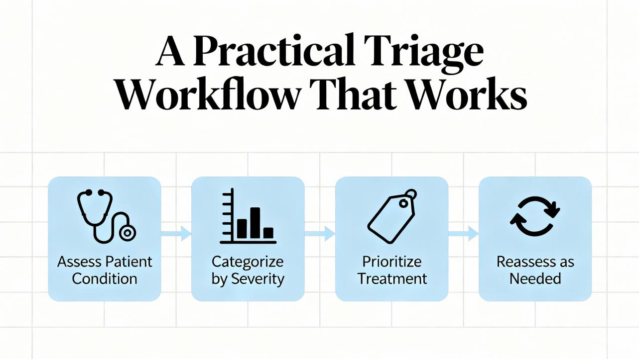
A Practical Triage Workflow That Works
In plants where uptime is money, the fastest path to restoration is disciplined and repeatable. The triage sequence below is the one I recommend and practice. It is deliberately configurationŌĆæfirst, infrastructureŌĆæaware, and instrumentationŌĆæfinal so that you do not mask configuration problems by overŌĆætuning hardware.
Start by stabilizing power to the rack. Check the rackŌĆÖs power modules and the feed supplying them, preferably from a doubleŌĆæconversion UPS with sufficient battery to ride through generator transfers and branch disturbances. If a power module shows a fault LED or if logs show recent undervoltage, swap the module and confirm that your auxiliary power circuit is delivering a clean sine wave without dips. This step aligns with powerŌĆæfailure troubleshooting guidance summarized in the Actech Parts 3500 guide.
Move to configuration integrity. Using the vendorŌĆÖs configurator, connect to the rack and read the ŌĆ£as foundŌĆØ configuration. Compare slotŌĆæbyŌĆæslot definitions to the modules physically present. Mismatch between defined and actual module types is a classic source of rack configuration faults, particularly after maintenance that required module replacement. Check firmware levels against what the configuration expects and update firmware or revise configuration to a knownŌĆægood, versionŌĆæcontrolled baseline.
Validate communications mappings next. If you publish measurements to a DCS or HMI through a 3500/92 EGD gateway or other gateway, open both producer and consumer configurations and confirm that exchange IDs, IP addresses, and update rates match. Multicast environments must have IGMP snooping correctly enabled with a querier on the VLAN; otherwise, data can flood or be filtered unpredictably. Confirm that every IP in the topology is unique and that firewall or NIC powerŌĆæsaving settings on HMIs are not interfering. The Mark VIe case mentioned earlier is a representative example of how a gateway can be NOT OK while the rack is OK due to a configuration or network condition.
Only after those checks move to instrumentation. For proximity probes, begin with a gap voltage check that holds steady for at least a dozen seconds, and perform a gentle cable tap test. Any change in gap voltage during light cable agitation indicates cable or probe issues. If the basic checks are solid, remove the probe only after marking its insertion depth or counting threads, inspect the tip for metallic debris or scoring, and measure resistance of the probe and extension cable against the manualŌĆÖs modelŌĆæspecific values. If needed, use a micrometer to verify linearity, substituting a knownŌĆægood extension cable and Proximitor to identify the bad actor. These steps are standard practice described by instrumentation technicians and compiled by Inst Tools.
As a final step, revisit alarm and trip handling in the context of protection versus condition monitoring. Protection alarms and trips belong to the rack and must be conservative and simple; conditionŌĆæmonitoring alarms in software can be more nuanced and stateŌĆædependent. Baker Hughes has published guidance on setting alarm levels that favors early baselining and stateŌĆæaware thresholds in condition monitoring software and cautions against overreliance on overall severity limits for diagnostics. This separation prevents nuisance trips while still highlighting issues early.
Networking Pitfalls with the 3500/92 EGD Gateway
The 3500/92 is a highŌĆæspeed EGD producer designed to make rack measurements available to GE control systems and HMIs that subscribe as consumers. EGD uses UDP and multicast, which is robust and lowŌĆælatency but punishing of configuration errors. If a rack configuration includes channels that the gateway publishes, and the gatewayŌĆÖs exchange map points to those measurements, the gateway will stay healthy. If the gateway expects exchanges that do not exist in the rack or if the IP addresses, port numbers, or exchange IDs do not match the consumerŌĆÖs expectations, you will see a dark COMM LED and a flickering OK LED on the gateway while the HMIs show blank or stale vibration values. Plants have reported sequential outages across trains with intervals under an hour when multicast control on the switch was misconfigured or when duplicate IP addresses caused intermittent subscription loss. The corrective actions in those reports are consistent with standard operational technology network hygiene: validate producer and consumer configurations, enable IGMP snooping with an active querier on the VLAN, segment traffic where appropriate, and update gateway firmware when stability issues are suspected. These observations have been echoed by experienced controls engineers in public forums and align with what I have seen during commissioning and troubleshooting on turbine trains.
When It IsnŌĆÖt the Rack: Instrumentation and Machine Conditions
Configuration faults can be triggered by instrumentation that behaves out of range. A proximity probe system is not just a probe; it is a matched set of the probe, extension cable, and Proximitor driver. Baker Hughes Bently Nevada emphasizes that matching matters because the sensitivity and linearity of the eddyŌĆæcurrent system depend on the combined length and calibration of those three parts. If a plant mixes part numbers or lengths, or if a probe is reinstalled without accurately restoring the gap, the monitor sees a bias it does not expect and can mark the channel NOT OK or invalid. Inst Tools captures a comprehensive and practical troubleshooting flow: keep the gap voltage steady, use the gentle jerk test to surface cable problems, verify resistance against the manual, and check linearity on a micrometer with substitution of knownŌĆægood components. These are quick, safe checks that often reveal that what looks like a configuration issue is actually a sensor chain problem.
Protection Alarms versus CM Alarms
A rack configuration fault often appears alongside other alarms, so it is essential to know which are protective and which are diagnostic. A protection threshold in a rack monitor is generally derived from standards and OEM limits for direct or overall measurements and is meant to be simple and reliable. Condition monitoring thresholds in software can be more sophisticated and stateŌĆædependent. Baker Hughes has published guidance that encourages using the first healthy baseline as an anchor for manual thresholds and combining that with learningŌĆæbased thresholds where enough history exists. The practical takeaway is that a configuration fault should be handled in the rack first to restore the integrity of the protection channel; after that, CM alarms can be adjusted, suppressed briefly, or made stateŌĆæaware to avoid nuisance during transients. When in doubt, remember that trips belong to protection logic and diagnostics belong to software; the wrong place for a clever threshold is in trip logic.
Power Quality and Rack Reliability
A surprising number of configuration faults trace back to power quality during maintenance or software updates. A rack that loses power or browns out while an engineer is loading a configuration is at risk of an incomplete or corrupted dataset. In facilities where I am responsible for reliability, I insist that all protection racks be on conditioned power with adequate holdŌĆæup time, and that firmware updates and configuration loads be done only when the rack is known to be on a stable UPS circuit. Power module faults are straightforward to localize with onŌĆærack diagnostics and with methods summarized in the Actech Parts troubleshooting guidance: check the feed, replace a faulted power module, and confirm proper installation. This is an area where collaboration with the power group pays off because the right UPS topology and battery maintenance keep these subtle problems from happening at all.
A Short Reference for Causes and Correctives
Plant teams appreciate a concise, shared reference that converts symptoms into actions. The table below extends the mapping with explicit checks to record during a rack configuration investigation. It is a working form I keep in my commissioning binder.
| Check item | What good looks like | Notes |
| Module identity and slotting | Product ID matches configured module and slot keying | Verify against a versionŌĆæcontrolled rack layout drawing before powerŌĆæup |
| Firmware and configurator version | Supported by the current configurator and dataset | Align firmware to what the saved dataset expects before loading |
| Configuration checksum | Clean readback from rack after load | If checksum fails, reload under stable power from UPS and retest |
| Gateway producer and consumer maps | Exchange IDs, IPs, and rates match on both ends | Confirm multicast control on the switch and eliminate duplicate IPs |
| Time synchronization | NTP or equivalent within a few seconds across devices | Time drift can upset some consumer subscriptions and logs |
| Probe gap and bias | Stable gap voltage midŌĆærange for the probe system | Perform gentle cable agitation test; no motion in DC bias |
| Linearity on micrometer | Within manual tolerance across travel | Substitute knownŌĆægood extension or driver to isolate the fault |
| Grounding and shielding | SingleŌĆæpoint scheme; cable shields terminated per manual | Avoid ground loops that show up as erratic vibration noise |
| Power quality | Clean, conditioned supply with rideŌĆæthrough | Avoid brownouts during firmware or configuration loads |
Confidence notes: the specific behaviors, such as checksum validation after loads and the effect of multicast configuration on EGD traffic, are highly consistent with vendor documentation and reported cases. The influence of time synchronization on EGD consumers is plausible and observed in the field but not explicitly documented in the public materials summarized here, so treat it as medium confidence and confirm on your platform.
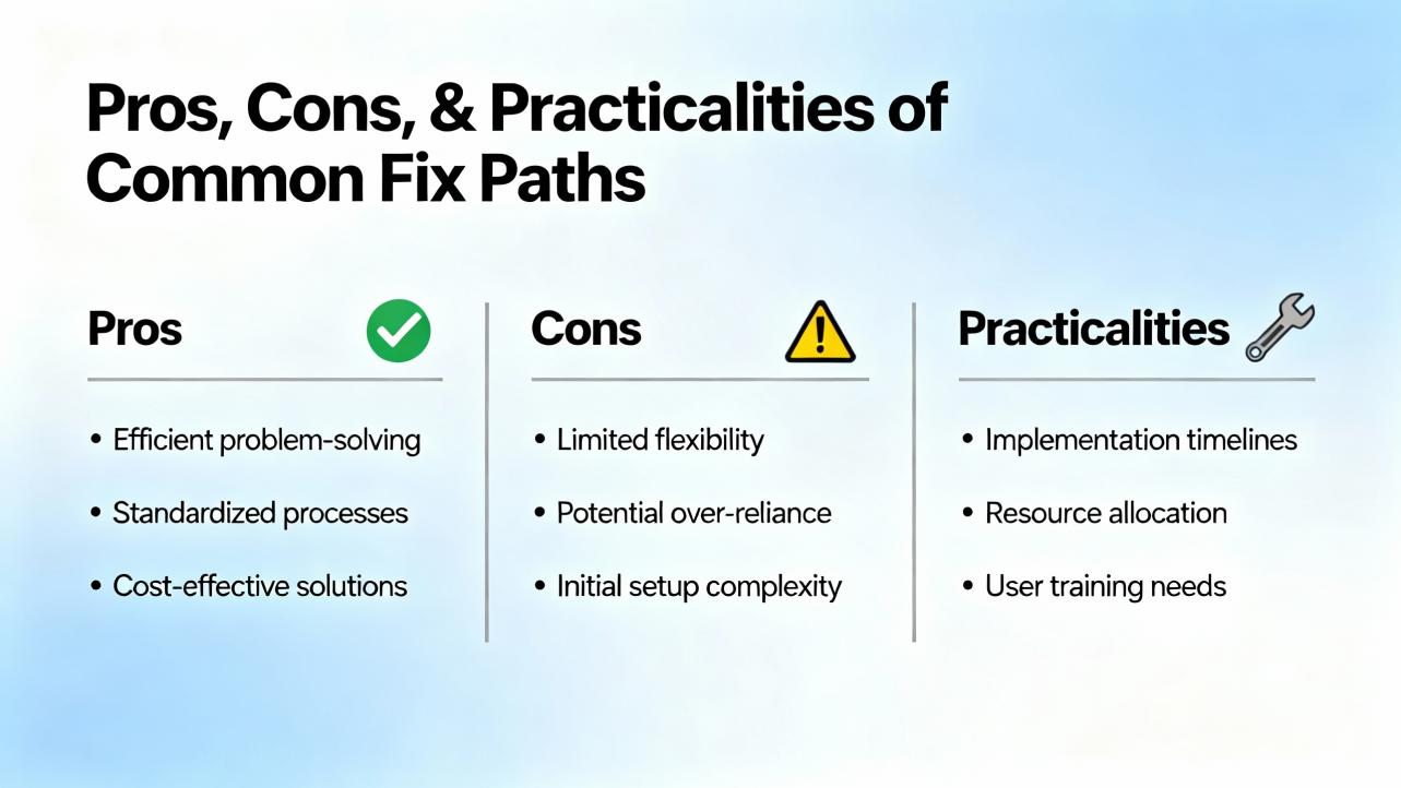
Pros, Cons, and Practicalities of Common Fix Paths
Configuration reŌĆæalignment is usually the fastest, but it is only durable if supported by the right infrastructure. Updating firmware to versions supported by the saved dataset avoids reŌĆæengineering, yet it can be constrained by cybersecurity and validation requirements. ReŌĆæauthoring a configuration for new module revisions is flexible, but it demands careful regression testing with System 1 connectivity and alarm logic. Network remediation like enabling IGMP snooping and adding a querier stabilizes EGD multicast at scale, though it adds switchŌĆæside administration and change control. Instrumentation replacement, especially in proximity probe systems, is definitive when gaps and linearity are off, but it requires downtime and careful reŌĆægapping, ideally with mechanical support present to inspect probe targets. There is no single right answer; pick the path that fixes the immediate fault with the least plant risk and then schedule the infrastructure work that reduces recurrence.
Care, Spares, and Buying Tips for Reliability
Spare strategies make or break recovery time. Keep one knownŌĆægood 3500/92 gateway on the shelf if your architecture depends on EGD to feed HMIs or controls, because swapping a suspect gateway is a fast way to divide network from rack issues. Maintain at least one fully matched set of proximity probe, extension cable, and Proximitor per model installed. Mixing vendors or lengths is tempting but often leads to bias and linearity headaches that look like configuration faults. Invest in managed Ethernet switches that support IGMP snooping and querier functions if you multicast, and segment traffic so that condition monitoring does not share bandwidth with protection or safety networks. Standardize on firmware levels by train and keep a locked copy of the configurator that matches those levels. Finally, place the rack power on conditioned UPS circuits with periodic battery tests; plants frequently discover that correcting UPS battery drift prevents a class of phantom configuration problems. These recommendations are based on dayŌĆætoŌĆæday experience and are consistent with the manufacturerŌĆÖs emphasis on matching transducer sets, disciplined configuration management, and robust networking.
When to Call the Vendor and What to Expect
Persistent rack configuration faults that recur after module and dataset alignment deserve vendor attention. The manufacturerŌĆÖs global services organization staffs hundreds of engineers across dozens of countries and provides both remote and onŌĆæsite support spanning startup, optimization, and lifecycle health checks. In my experience, the fastest path to a productive engagement is to prepare a package that includes the rack configuration file, a slot map of installed hardware with serial numbers and firmware levels, recent event logs, and a short timing diagram of when the fault appears relative to plant operations. That structured handoff shortens the time from ŌĆ£we are downŌĆØ to ŌĆ£we are safeŌĆØ and lets the support team zero in on the mismatch or instability that is actually causing the fault. This approach mirrors bestŌĆæpractice recommendations published by the vendor for commissioning, alarm governance, and periodic system health assessments.
Definitions You Will Use in Conversation
Clarity helps crossŌĆæfunctional teams resolve faults quickly. A proximity probe system measures nonŌĆæcontact shaft motion using an eddyŌĆæcurrent probe, a matched extension cable, and a Proximitor driver whose DC output is the gap voltage that represents average shaft position, while the AC component is vibration. A Keyphasor reference is a onceŌĆæperŌĆærevolution timing pulse used to phase vibration. EGD or Ethernet Global Data is a highŌĆæspeed producerŌĆōconsumer protocol used in GE control environments; the 3500/92 gateway publishes the rackŌĆÖs measurements as EGD exchanges, and consumers like Mark VIe subscribe to them. The OK or NOT OK status is the rackŌĆÖs oneŌĆæbit declaration of health at the module or channel level; rack configuration faults force NOT OK to ensure you do not trust protection from a misconfigured system. These definitions track the manufacturerŌĆÖs published descriptions of vibration measurements, transducer systems, and communications.
A Short FAQ for Busy Engineers
Q: What does a ŌĆ£rack configuration faultŌĆØ actually cover in a 3500 installation? A: It covers mismatches between the configuration dataset and what is physically present and running in the rack, including wrong or missing module types in keyed slots, unsupported firmware, corrupted or partial datasets, and communications or gateway maps that reference measurements that do not exist. The supervising interface asserts NOT OK until the discrepancy is removed.
Q: Can an EGD gateway be NOT OK while the rack is OK? A: Yes. If producer and consumer settings for exchange IDs, IP addresses, or update rates do not match, or if multicast control is misconfigured on the switch, a 3500/92 gateway can report NOT OK while the rack measurements and modules are otherwise healthy. Controls engineers have documented such cases in multiŌĆætrain plants, and the remedy is to align configurations and stabilize multicast with IGMP.
Q: How do I separate a configuration problem from a probe problem? A: Stabilize power and configuration first, then perform simple instrumentation checks. Hold gap voltage steady for a dozen seconds, apply a gentle cable tap to look for bias shifts, inspect the probe tip, and verify resistance and linearity against the manual using a micrometer. If a knownŌĆægood probeŌĆōcableŌĆōdriver set behaves correctly while the installed set does not, the fault is in the sensor chain and not the rack dataset.
Q: Do I need to update firmware to clear a configuration fault? A: Sometimes. If a moduleŌĆÖs firmware revision is not supported by the dataset or configurator you are using, align firmware or change the dataset to a revision that supports the module. Make firmware and configuration changes under conditioned power with controlled procedures to avoid halfŌĆæapplied updates.
Q: What are the best preventive measures? A: Keep the rack on a conditioned UPS feed, standardize firmware and configurator versions, maintain matched transducer spares, validate EGD multicast with IGMP snooping and a querier, and run periodic health checks that compare ŌĆ£as foundŌĆØ hardware and configuration to the versionŌĆæcontrolled baseline. These steps reduce configuration drift and reduce mean time to repair when faults do occur.
Takeaway
Rack configuration faults are not mysteries; they are symptoms of misalignment among configuration, hardware identity, firmware levels, communications mappings, and sensor baselines. Treat the rack as a protection system first by stabilizing its power, aligning its dataset with the hardware present, and confirming that its gateways are speaking the same language as their consumers. Only then turn to instrumentation, where disciplined probe checks resolve the remainder. In parallel, invest in preventive measures that pay back quickly: matched spares, IGMPŌĆæaware networks, conditioned power, and configuration governance. This approach is consistent with both the manufacturerŌĆÖs guidance and the lived experience of practitioners in plants that run hard and cannot afford surprises. Where specific module behaviors or error wordings vary by firmware family, consult the official manuals or engage the vendorŌĆÖs support team to confirm details. The strategy outlined here is high confidence because it aligns with published guidance from the vendor and with field cases reported by experienced engineers; apply it, and rack configuration faults become short, teachable moments instead of long, costly outages.
References
- https://assetmanagementprofessionals.org/discussion/bently-rack-protection-and-the-not-ok-signal
- https://www.machineryanalysis.org/post/troubleshooting-orbit-analysis-using-bently-nevada-system-1-10170139
- https://studylib.net/doc/27017185/bently-nevada-3500-proximitor
- https://www.bntechsupport.com/GEA17502.pdf
- https://actechparts.com/bently-nevada-3500-complete-guide/
- https://www.artisantg.com/info/Baker_Hughes_Bently_Nevada_3300_15_MaintenanceManual_Manual_202051813530.pdf?srsltid=AfmBOorXg0Ic71yAqh4AUjLVacv8tt_YmpJa2xMF9qwrUnSOykFvFFiZ
- https://www.bakerhughes.com/bently-nevada/support-services
- https://instrumentationtools.com/vibration-monitoring-system-step-by-step-troubleshooting-guide/
- https://www.powergearx.com/resolving-zero-output-troubleshooting-bently-nevada-3300-nsv-metric-probe-issues/
- https://www.scribd.com/document/258461901/Bently-Case-Study-1


 Videos
 News
News Applications


Leave Your Comment