Modern industrial and commercial power systems lean heavily on rotating machinery: gas and steam turbines driving generators, large motors on cooling towers, and engine-driven sets that back up UPS and inverter banks. In that environment, a machinery protection rack is not a ŌĆ£nice to haveŌĆØ accessory. It is a safety and availability device that can keep your plant online when something goes wrong. The Bently Nevada 3500/22 Transient Data Interface (TDI) sits at the center of that rack, and the official datasheet and manuals for it are some of the most important documents in your reliability toolbox.
As a power system specialist, when I evaluate a 3500/22 installation I do not start at the hardware. I start at the datasheet, the rack installation manual, the 3500/22 operation manual, and the cybersecurity advisories issued for the module. Those documents, combined with real-world wiring and commissioning practices, make the difference between a SIL 2-rated protection system that behaves as designed and a noisy, fragile system that trips at the worst possible time.
This article walks through the official 3500/22 technical documentation from the point of view of power and reliability engineering. It distills what the datasheet actually covers, how it fits with the broader 3500 documentation set, the installation practices that matter most, and the cybersecurity gaps you will not see highlighted on a marketing flyer.
Where the 3500/22 Fits in Your Power Architecture
The Bently Nevada 3500 platform, as described by Baker Hughes, is a modular machinery protection system that provides vibration and position monitoring with a SIL 2 safety rating and multiple hazardous-area approvals. A 3500 rack can host a mixture of proximity, seismic, speed, temperature, gas detection, and relay modules to protect critical rotating equipment in refineries, petrochemical plants, hydroelectric facilities, and similar environments.
Within this rack, the 3500/22 TDI acts as the communication gateway. Field experience summarized by Ubest Automation describes the 3500/22M Transient Data Interface as the module that gathers both dynamic data such as vibration waveforms and static data such as gap, speed, and temperature from all other rack modules, then delivers that data over Ethernet to Bently Nevada System 1 software or external control systems. For a power engineer, that means the 3500/22 is the bridge between your mechanical protection domain and the rest of your control and monitoring infrastructure.
The 3500 rack typically combines the TDI with several specialized monitors. Baker Hughes documentation highlights a few of the most relevant to power generation and mechanical drive applications. The 3500/40M Proximitor Monitor accepts inputs from proximity and seismic transducers, conditions those signals, and compares them against user-programmable setpoints to drive alarms and relay logic. The 3500/42M Proximitor/Seismic Monitor offers four programmable channels that can be configured for radial vibration, thrust position, differential expansion, eccentricity, or acceleration and velocity measurements. The 3500/44M Aeroderivative Gas Turbine Monitor focuses on aeroderivative gas turbine vibration, while the 3500/46M Hydro Monitor is specifically engineered for hydro turbine generators, including air-gap and dynamic pressure measurements.
All of these monitors rely on the rack for power and for relay logic, but they rely on the 3500/22 to make their data useful outside the panel. If the 3500/22 is mis-specified or mis-installed, your control system may lose situational awareness even though the individual monitors still measure correctly.
You will also encounter another use of the ŌĆ£3500/22MŌĆØ designation in third-party catalogs, where it is associated with a TMR (Triple Modular Redundancy) relay module. According to one such technical overview, this 3500/22M TMR relay module uses three independent relays to generate a single logical output, with a three-to-two voting mechanism that requires at least two agreeing inputs before a trip is asserted. Each relay can be driven by programmable alarm logic based on warning and danger signals from multiple monitoring channels. In addition, the relay module invalidates the alarm contact for any data channel whose OK status is not healthy, so a bad channel cannot force an inappropriate trip. Whether you are using a dedicated TMR relay module or a standard 3500/33 relay module, the key takeaway is that shutdown logic lives in the relay cards but is configured through the same rack configuration software environment used by the 3500/22 interface.
Because the documentation set references both 3500/22 and 3500/22M Transient Data Interface manuals, and some third-party sources use 3500/22M in the context of TMR relay hardware, the first practical step when you pick up a datasheet is to confirm the exact part number and manual number printed on its cover and match them to the hardware label on the module in your rack. That simple check prevents months of confusion down the line.
What the Official Datasheet and Manuals Actually Cover
From a reliability perspective, the most useful part of the 3500/22 documentation is not a single datasheet, but the combination of several official documents. A technical review compiled by Actech Parts notes that the complete 3500 System documentation set includes detailed technical specifications and parameter tables, complete installation and configuration guides, maintenance manuals and troubleshooting procedures, along with electrical diagrams and wiring schematics. Additional support materials include dimensional drawings and mechanical blueprints, performance test data and characteristic curves, compatibility and integration guidelines, and safety specifications with certification information.
The 3500/22M Transient Data Interface Operation and Maintenance Manual, identified by Bently Nevada as document 161580-01, sits within this larger set. The portion of that manual available in the research notes primarily contains legal and contact information, copyright notices, and a list of Bently Nevada trademarks such as Keyphasor, Proximitor, and various condition monitoring brands. It also includes a ŌĆ£subject to change without noticeŌĆØ disclaimer and directs users to corporate contacts in Minden, Nevada for updated information. That front matter is easy to skip, but for a long-lived power asset it is a reminder that you must periodically refresh your documentation from current Bently Nevada sources rather than relying on a decade-old printout.
The broader installation and configuration guidance for the 3500 Monitoring System is spread across several manuals referenced in the 3500 Monitoring System Installation Manual. These include the 3500 Monitoring Rack installation guide, the 3500 Monitoring System Installation and Operation Guide (document 163860-01), the 3500 Monitoring System Configuration and Utilities Guide (document 129777-01), module-specific operation and maintenance manuals for monitors such as the 3500/77M reciprocating cylinder pressure monitor and the 3500/65 temperature monitor, and the 3500/33 16-Channel Relay Module manual. The 3500/22M Transient Data Interface Operation Manual sits alongside these, emphasizing that the TDI is part of an integrated architecture.
The rack operation and control section of the 3500 Monitoring System documentation explains how to verify configuration and interpret the rackŌĆÖs front-panel indicators. Configuration is defined as the process of setting system, module, and channel options so that all modules in the 3500 rack work together correctly. After power is applied, the rackŌĆÖs CONFIG OK LED must be on to indicate a complete and correct configuration. If it is not lit, the manualŌĆÖs guidance is to contact your local Bently Nevada representative rather than guessing at a fix. The same section explains that the CONFIG OK LED can blink at about five hertz under certain configuration-related conditions and that operating the Reset switch will stop this blinking as part of clearing latched alarms and resetting Timed OK and Channel Defeat indications.
The rack also includes a Key switch on the Rack Interface Module, which selects between RUN and PROGRAM positions. In RUN, the rack continues normal operation but cannot be configured, effectively locking current settings. In PROGRAM, the rack can be configured while continuing to operate normally, allowing controlled online configuration changes. Removing the key mechanically locks the Rack Interface Module in either RUN or PROGRAM, giving you a physical layer of access control. As you will see later, this simple mechanical control becomes a powerful cybersecurity tool when combined with what Nozomi Networks Labs has disclosed about the 3500/22 TDIŌĆÖs Ethernet vulnerabilities.
A separate section of the installation manual deals with replacing I/O modules and power input modules. The procedure instructs technicians to verify channel measurement parameters using the Verification utility in the 3500 Rack Configuration program together with the verification procedure in the specific moduleŌĆÖs reference manual. Before removing any module, you are directed to consult the applicable reference manual to understand how rack behavior may be affected and to follow any special handling and personal safety requirements. Because 3500 modules require valid configuration settings to operate correctly and replacement modules ship unconfigured, the manual recommends uploading and saving the existing module configuration before removal and then downloading that configuration to the replacement hardware after installation. Field wiring must be clearly labeled before disconnection, and final verification is performed by checking the module LEDs against the ŌĆ£Reading the LEDsŌĆØ guidance in the operation manual. These are basic steps, but they are often skipped in the rush to restore service.
To bring this material together, it is helpful to think of the 3500/22 datasheet and manuals as part of a layered documentation model.
| Document or section | Focus area | How it supports 3500/22 use |
| 3500/22M Transient Data Interface O&M manual (161580-01) | Functional description, operation, and maintenance | Explains how the TDI gathers data, communicates, and is serviced |
| 3500 System Installation and Operation Guide (163860-01) | Rack installation, module placement, operation overview | Defines how the TDI fits into the rack and interacts with others |
| 3500 Configuration and Utilities Guide (129777-01) | Rack configuration software and utilities | Describes how to configure TDI, monitors, and relay logic |
| Module-specific O&M manuals (40M, 42M, 44M, 46M, 33, etc.) | Sensor signal conditioning and protection logic | Show what data flows through the TDI and what trips the relays |
| Vendor technical analysis and troubleshooting guides | Practical field troubleshooting and best practices | Translate official specs into actionable installation guidance |
The official datasheet gives you the range of what the 3500/22 can do. The manuals and system guides tell you how to do it safely. Field-proven wiring and rack layout practices from experienced vendors translate that theory into a reliable installation.
Designing the Rack: Slotting, Environment, and Layout
When you read the 3500/22 datasheet in isolation, it is easy to focus on Ethernet protocols and sampling capabilities. In practice, the most important parts for a power engineer are surprisingly physical: where the module sits in the rack, how the cabinet is built, and how the cables are routed.
The Bently Nevada 3500 monitoring rack forms the core of a machinery protection system. Guidance from Ubest Automation emphasizes that the 3500/22M TDI must occupy Slot 1 of the rack chassis in a standard configuration, or Slot 2 when a redundant TDI is used. The power supply modules are typically placed at either end of the rack to even out thermal distribution. Protection modules such as the 3500/42M are arranged so that their physical order mirrors the machine train sequence. Relay output modules are grouped at the far right, where they can be readily accessed for shutdown wiring and functional testing. This arrangement is not just aesthetic. It simplifies consistency checks between the rack layout, the wiring diagrams, and the 3500 configuration software, which is critical when you are troubleshooting a trip in the middle of the night.
Environmental and cabinet conditions are another area where the datasheet and manuals should drive design decisions. UbestŌĆÖs field guide recommends confirming that the installation cabinet meets the specified temperature and humidity ranges and is mounted on a clean, vibration-isolated surface. Adequate airflow, especially around power supplies, must be ensured so that components do not run at the top of their thermal envelope. If the installation is in a classified area, the cabinet design and installation must comply with the relevant hazardous area ratings referenced in the 3500 documentation. In power plants and large commercial facilities, it is common to see 3500 racks shoehorned into crowded MCC rooms or control cabinets. Using the environmental specifications in the datasheet as a hard constraint rather than a suggestion avoids subtle degradation in reliability over the life of the system.
A simple real-world example makes this concrete. Consider a 3500 rack installed in a generator control panel adjacent to high-current bus bars. If the rack is mounted on a non-isolated wall subject to vibration from nearby switchgear operations, and if hot air from the bus compartment is allowed to wash over the rack, the module temperatures and vibration levels can exceed what the datasheet assumes. That does not cause an immediate failure, but over years it can shorten the life of connectors and I/O modules. Aligning the cabinet design with the documented environmental limits is one of the cheapest reliability improvements you can make.
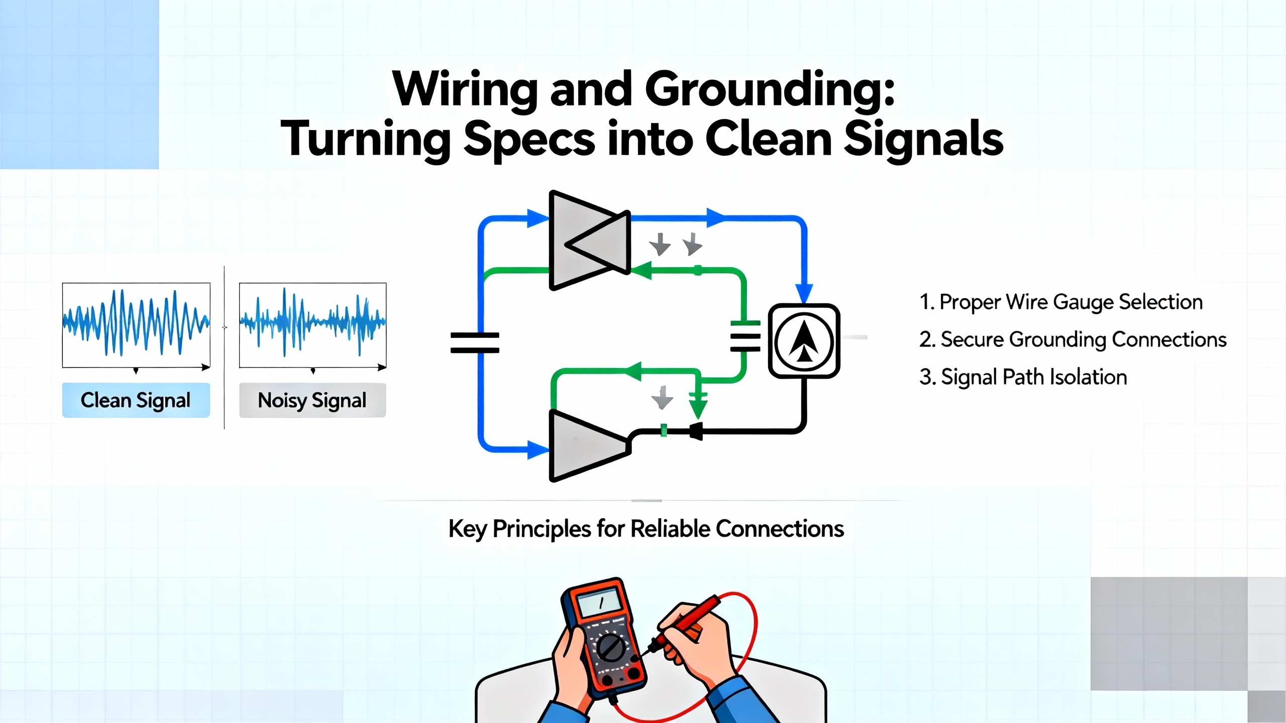
Wiring and Grounding: Turning Specs into Clean Signals
For the 3500/22 and the monitors it serves, the quality of field wiring determines the quality of diagnostics. The datasheet tells you what the module can measure; your wiring determines whether it actually does. Ubest AutomationŌĆÖs wiring and rack layout guide for the 3500/22M TDI captures several best practices that are entirely consistent with what experienced vibration specialists see in the field.
For dynamic sensor inputs such as proximity probes and accelerometers, the guidance is to use shielded twisted-pair cable in the 18 to 22 AWG range. Each conductor should be terminated with a ferrule or suitable lug to prevent stray strands that can create intermittent shorts or high-resistance connections. Every cable and terminal block should be clearly labeled so that future loop checks and troubleshooting can be performed without guesswork.
Signal separation is just as important as cable construction. Industrial automation standards and practical experience both say that high-voltage power lines and low-level sensor signals should not share trays or conduits. Ubest calls out a frequent source of trouble: running variable-frequency drive output cables alongside vibration sensor wiring. In those cases, even a careful twisted pair can pick up inductive noise. Maintaining a physical separation on the order of three to five feet between VFD outputs and vibration sensor cables, and using dedicated routes for low-level signals, dramatically reduces the risk of cross-talk. Ethernet and other communication lines should also be kept separate from dynamic sensor wiring, again following the datasheetŌĆÖs recommendations for shielding and separation.
Grounding is where many otherwise well-built installations fail. The Ubest guidance describes correct grounding as perhaps the most important factor in noise elimination. All signal shields should terminate at a single-point ground within the rack or cabinet, typically a dedicated ground bar that is securely bonded to the plantŌĆÖs main industrial ground network. Sensor shields should not be grounded at both the field device and the rack; doing so creates a loop in which ground potential differences can drive unwanted current through the shield. In vibration monitoring, that current shows up as high-frequency noise or a constant offset in the low-level signal, causing an unstable baseline.
There is a straightforward way to test for ground loops, described in the same field guide. With the system de-energized and safely accessible, you can use a multimeter to measure the AC voltage potential between the cable shield at the field device and the main plant ground. If you observe a significant AC voltage, even on the order of a few hundred millivolts, that difference in potential is enough to drive current through a shield grounded at both ends, indicating a likely ground loop. The definitive solution is to enforce single-point grounding at the rack and remove any shield connections at the field device.
Sensor-specific wiring requires additional care. For proximity probes, the recommendation is to route the cable from the probe driver directly to the rack channel input with no intermediate splices, and to locate the probe driver as close to the 3500 rack as feasible. Long cable runs add capacitance and resistance to the circuit. Ubest gives the example of proximity probe cables on the order of three hundred feet, where increased impedance can lead to signal attenuation and phase shifts in the Keyphasor signal. In those cases, Bently Nevada recommends strategies such as remote I/O junction boxes or driver types suited for long cable runs, and the total cable length must be compared against the limits published in the official specifications.
For accelerometers and velocity sensors, the field advice is to implement single-point grounding at the rack terminal base only and to avoid any shield connection at the field device. This prevents ground loops and keeps the sensor signal reference consistent. During commissioning, gap voltage checks for probes and impact tests for accelerometers provide a quick confirmation that wiring and polarity are correct before you rely on the data.
On the communication side, the 3500/22 datasheet specifies Ethernet-based communication to System 1 and other systems, and Ubest recommends using high-quality Cat5e or Cat6 shielded twisted-pair Ethernet cable. Minimum bend radius requirements must be respected to avoid kinking the cable, and all Ethernet runs should be physically isolated from power lines and motor leads. Keyphasor and speed inputs, which supply the phase reference for dynamic analysis, should also use shielded twisted pair, and their cable lengths should be kept as short as practical to minimize signal degradation and timing skew. Because the 3500/22 relies on a clean Keyphasor signal for accurate waveform processing, poor wiring here can compromise all subsequent diagnostics.
In short, the wiring and grounding practices called out in field guides amplify what the datasheet implies but does not always spell out. They are the practical expression of the moduleŌĆÖs measurement capabilities.
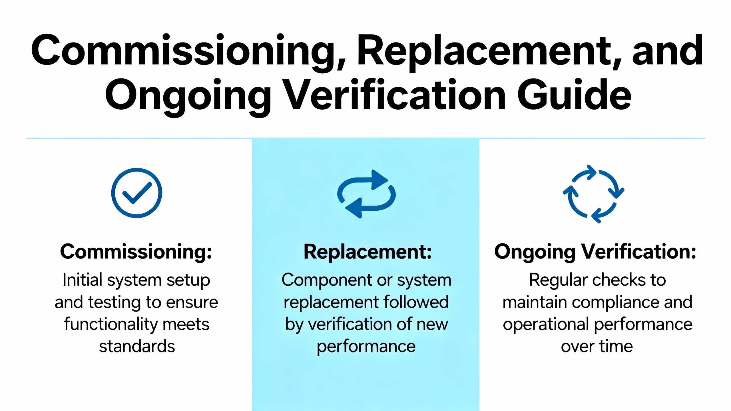
Commissioning, Replacement, and Ongoing Verification
The 3500/22 datasheet tells you what the module will do when everything is correct. The installation and operation manuals tell you how to get there and stay there. Commissioning is where those instructions become real.
According to UbestŌĆÖs commissioning steps, pre-energization checks should verify sensor polarities, shield bonds, and power supply voltages independently. This aligns with the 3500 installation manualŌĆÖs emphasis on verifying measurement parameters via the 3500 Rack Configuration program and module reference manuals. Dynamic testing then includes gap voltage checks for probes, impact tests for accelerometers, and validation of transient data capture through System 1. These steps not only verify individual channels but also test the end-to-end signal path that runs through the 3500/22.
Documentation is treated as part of commissioning rather than an afterthought. Ubest recommends handing over complete as-built drawings, calibration certificates, and commissioning test results to the asset owner. From a power-system reliability standpoint, embedding those documents into your maintenance management system alongside the equipment record ensures that future modifications reference the same baseline.
The replacement of I/O modules and power input modules is another area where official documentation is explicit. The 3500 installation manual makes clear that the replacement procedure applies only to the I/O module of a monitor or the Power Input Module of a power supply. Before removing any module, you are instructed to upload and save the existing configuration, since replacement modules arrive unconfigured. The physical sequence involves removing the main module from the rack, disconnecting field wiring from the I/O module, removing the old I/O module, installing the new one, reconnecting field wiring, and reinstalling the main module. All field wiring must be clearly labeled to avoid errors. After reinstalling, the saved configuration must be downloaded to the new module using the configuration utilities, and final verification is performed by checking LED behavior against the operation manual.
For power-system applications where downtime is expensive, these steps are more than procedural detail. They are what allow you to replace a failed I/O board on a turbine vibration monitor or a temperature card on a generator stator without introducing new configuration errors that might leave the machine unprotected.
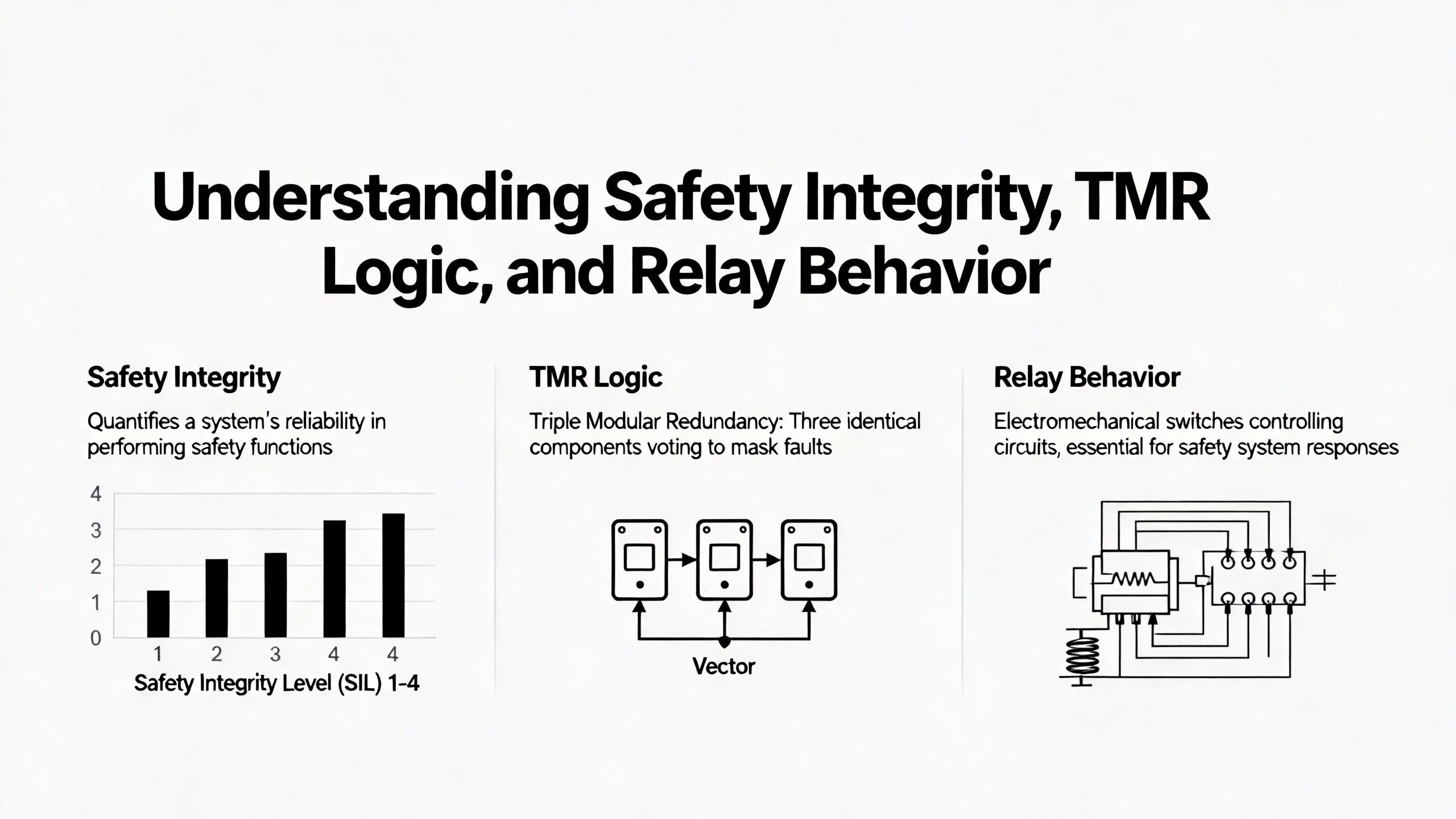
Safety Integrity, TMR Logic, and Relay Behavior
The Bently Nevada 3500 system is positioned by Baker Hughes as a SIL 2-capable machinery protection platform. Meeting that claim in a live plant requires both correct configuration and correct relay logic.
The relay hardware is where detector signals turn into trips. One third-party technical overview describes a 3500/22M 288055-01 TMR relay module that implements Triple Modular Redundancy. In that design, three independent relays generate a single logical output. A three-to-two voting mechanism is used with a TMR framework interface module and three monitor modules. At least two of the three outputs must agree before the relay trips, reducing the risk that a single component failure or a single bad channel will cause a spurious shutdown. Each relay output can be driven by programmable Alarm Drive Logic configured via the 3500 configuration software, using AND and OR functions on warning and danger alarms across multiple channels. If a data channelŌĆÖs OK status is not healthy, the relay module invalidates the associated alarm contact signal, ensuring that a failed channel does not participate in the trip logic.
The same overview notes that the 3500 series, including this TMR relay configuration, is designed to meet standards such as ISA S84.01-1996 for safety instrumented systems and API 670 for mechanical protection in critical sectors like oil and gas. For power applications, that means the hardware and logic structures line up with industry expectations for safety integrity. Redundancy support can be enhanced by pairing two TMR relay modules with a TMR relay I/O module and programming both relay modules to perform the same function, providing an additional layer of backup.
From a practical point of view, this makes the 3500/22 configuration environment and the relay modules inseparable. You configure your vibration and position monitors, define warning and danger setpoints, and then use the same 3500 configuration software to program how the TMR or standard relay modules respond. If you misunderstand the datasheet or misinterpret the configuration screens, you can defeat the advantages of Triple Modular Redundancy. Conversely, when you correctly implement a two-out-of-three voting scheme on key shutdown parameters, you greatly reduce the risk of nuisance trips without compromising protection.
Consider a generator train where three independent vibration monitors all measure shaft vibration at different bearings. With simple single-channel trips, a failed probe that loses its OK status but still produces noise might be enough to stop the machine. With a TMR relay that invalidates any channel whose OK status is bad and uses two-out-of-three voting on the remaining channels, that same failed probe becomes a maintenance alarm rather than a trip cause. The datasheet tells you that such logic is possible; the manuals and configuration guidelines tell you how to implement it.
Cybersecurity: What the Datasheet Does Not Say About the 3500/22 TDI
Datasheets for modules like the 3500/22 focus on functionality, environmental ratings, and electrical compatibility. They rarely highlight cybersecurity limits. Independent research has filled that gap. Nozomi Networks Labs has published a detailed analysis of the Ethernet-based 3500/22 TDI module, in which they reverse-engineered its proprietary clear-text protocol and discovered several vulnerabilities that matter directly to reliability and safety.
Their research identifies at least three distinct issues affecting 3500/22 TDI firmware versions up to and including 5.05 and later, for both USB and serial variants. The first, cataloged as CVE-2023-34437, is characterized as a high-risk information disclosure vulnerability. It allows an unauthenticated attacker with network access to exfiltrate both the ŌĆ£ConnectŌĆØ and ŌĆ£ConfigurationŌĆØ passwords via a crafted request. In practical terms, that means an attacker who can reach the TDIŌĆÖs Ethernet port can extract credentials that are supposed to protect configuration access, opening the door to full device compromise.
A second vulnerability, CVE-2023-34441, relates to the clear-text transmission of sensitive information. Nozomi reports that captured traffic exposes a static secret key reused across all authenticated requests and sessions. Because the key is not tied to a specific session or time window, once an attacker extracts it from any captured packet, they can craft arbitrary authenticated requests indefinitely. A third issue, CVE-2023-36857, enables authentication bypass via capture and replay of legitimate packets. Intercepted packets can be replayed to gain unauthorized access even without knowing the original credentials.
The combined impact of these issues is significant. Nozomi notes that attackers could potentially take full control of a 3500 rackŌĆÖs configuration, alter monitoring parameters, inject incorrect measurements, or cause denial-of-service conditions that impact industrial processes. For a power system, the risk is not only a direct trip, but also a gradual erosion of protection as setpoints are modified or channels are disabled without authorization.
The vendorŌĆÖs response, as summarized by Nozomi Networks, is that these vulnerabilities will not be patched on the legacy 3500/22 platform due to technical limitations. Instead, mitigation relies on hardening and network architecture. Recommendations include enforcing RUN Mode instead of CONFIG or PROGRAM Mode during normal operation, which aligns with the rackŌĆÖs Key switch behavior described earlier. By keeping the key in RUN and removing it, you physically prevent configuration changes even if an attacker acquires credentials.
Network segmentation is another core mitigation. Nozomi advocates isolating Bently Nevada 3500 systems and other legacy OT assets on dedicated network segments, ideally with unidirectional paths or strict firewall rules that prevent direct access from office or internet-connected networks. Strong, unique passwords should be enforced, avoiding reuse across devices or systems, and any non-default enhanced security features and security levels in the 3500 configuration utility should be enabled and configured. Bently Nevada has issued hardening guidelines to customers, and Nozomi has updated its threat intelligence to detect and alert on potentially vulnerable installations.
For a power-system reliability engineer, the practical message is clear. The 3500/22 datasheet gives you the functional benefits of Ethernet connectivity and transient data access. The Nozomi research reminds you that this connectivity comes with exploitable weaknesses that are not going away. You must treat the 3500/22 as a critical OT asset, enforce physical RUN mode, segment its network, and monitor traffic for abnormal patterns. Failing to do so means that a security incident could quietly undermine the protection provided by your machinery protection system.
A concise way to connect the technical findings with operational action is to map each vulnerability class to a mitigation focus.
| Finding from Nozomi Networks Labs | Primary impact | Mitigation focus |
| Password exfiltration (CVE-2023-34437) | Loss of configuration and connection credentials | Network isolation, strong per-device passwords, RUN Mode |
| Clear-text static key (CVE-2023-34441) | Long-term ability to forge authenticated traffic | Encryption at higher layers, segmentation, traffic monitoring |
| Capture-replay authentication bypass (CVE-2023-36857) | Unauthorized access via replayed packets | One-way or tightly controlled connectivity, logging and anomaly detection |
When you read the 3500/22 datasheet today, you should mentally append these security constraints to the Ethernet features it describes.
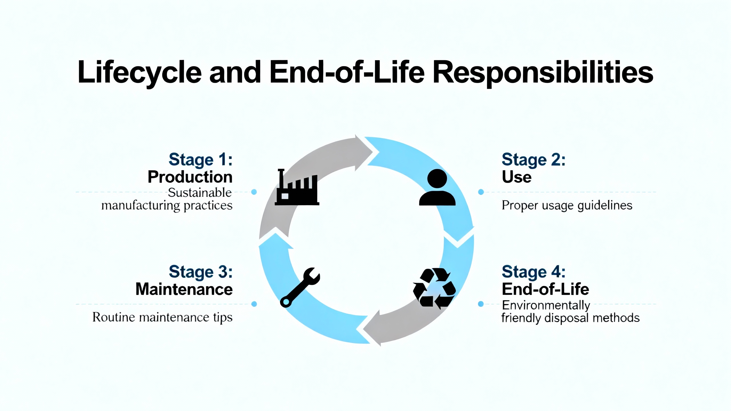
Lifecycle and End-of-Life Responsibilities
While most engineers focus on the early life of a 3500/22 installation, the official documentation also spells out responsibilities at end of life. The 3500 Monitoring System Installation Manual includes a Product Disposal Statement that applies to customers and third parties outside the European Union. It states that the party in control of the product at the time of disposal is solely responsible for proper disposal and explicitly prohibits disposing of the product in any way that violates applicable federal, state, local, or international laws. Bently Nevada LLC disclaims responsibility for end-of-life product disposal, placing legal and operational responsibility on the product owner or controlling entity.
For operators of industrial and commercial power systems, this matters because machinery protection racks often contain electronics that fall under specific disposal or recycling regulations. Incorporating the disposal guidance from the manual into your asset lifecycle plans ensures that when a 3500/22 is eventually replaced or upgraded, it is removed from service and disposed of in compliance with environmental and safety regulations.
The trademark and change-without-notice language in the 3500/22M Operation and Maintenance Manual also has lifecycle implications. Because Bently Nevada reserves the right to change product features and documentation without notice, it is essential to track the document numbers and revision levels associated with each installed rack. Including those references in your equipment records allows you to verify, years later, which version of the datasheet and manual your design and commissioning decisions were based on and whether any subsequent changes might warrant a review.
FAQ
How can I be sure I am using the correct 3500/22 datasheet and manual for my system?
The research notes show that the 3500 documentation set includes both 3500/22 and 3500/22M identifiers, with the Transient Data Interface Operation and Maintenance Manual identified as document 161580-01 and the broader configuration guide as 129777-01. Third-party sources also reference a 3500/22M part number for a TMR relay module. To avoid confusion, match the full part number and description printed on your moduleŌĆÖs label to the document number printed on the datasheet or manual cover. Then cross-check that combination against the references listed in the 3500 Monitoring System Installation and Operation Guide. Keeping those document numbers in your asset records prevents mixing guidance meant for different hardware.
Given the known vulnerabilities, is it still acceptable to connect a 3500/22 TDI to my plant network?
Nozomi Networks Labs has demonstrated that the 3500/22 TDIŌĆÖs Ethernet protocol includes vulnerabilities that allow password exfiltration, clear-text key reuse, and authentication bypass via replay. The vendor does not plan to patch these issues on the legacy platform, so safe use depends entirely on hardening. If you segment the 3500 network from general IT traffic, enforce strong unique passwords, enable all available security levels in the configuration utility, and physically lock the rack in RUN mode using the Key switch, you can substantially reduce risk. Many facilities continue to operate 3500/22 TDIs under those conditions, often with additional monitoring from OT security tools, but doing so without segmentation or RUN mode is increasingly hard to justify.
What is the single most important installation practice for clean, reliable data from a 3500/22-based rack?
Field guidance from Ubest Automation and other practitioners points to disciplined grounding and signal separation as the most critical factors. Using shielded twisted-pair cables for all dynamic sensors, terminating shields only at a single ground bar in the rack, keeping that bar bonded to the plantŌĆÖs main ground, and maintaining several feet of physical separation between high-voltage power or VFD cables and low-level sensor wiring do more to improve data quality than almost any other step. When those practices are combined with the commissioning procedures in the official manuals, such as gap voltage checks, impact tests, and verification of transient capture in System 1, the 3500/22 can deliver stable, trustworthy data over the long term.
In critical power environments, the 3500/22 is not just another module in a rack; it is the nerve center that turns vibration and position signals into actionable protection and diagnostics. Treat the datasheet and manuals as design requirements rather than optional reading, align your wiring and grounding with proven field practices, and harden the TDIŌĆÖs network presence with the same care you apply to your relays and breakers. That combination is what keeps your machinery protection working for you instead of surprising you.
References
- https://do-server1.sfs.uwm.edu/mirror/3A8I696197/journal/8A1I283/bently_nevada__3500__42__vibration__monitoring__system-manual.pdf
- https://studylib.net/doc/25708140/3500-22m-transient-data-interface-manual-161580-01
- https://actechparts.com/bently-nevada-3500-complete-guide/
- https://www.artisantg.com/info/Bentley_Nevada_3500_22M_Datasheet.pdf?srsltid=AfmBOooLzLn2WIAEyhqaCNOuH0fMrjIbdZhJMVpR4jViHXDfEupbvVin
- https://axcontroler.com/BENTLY/bently-nevada-3500-22m-288055-01-tmr-relay-module
- https://www.instrumart.com/assets/3500-System-Datasheet.pdf?srsltid=AfmBOopDMZoGkTAnfNIdiqMdp86gCNi0v60DCn7Xa_OqwP8pND_NXW3Y
- https://www.nozominetworks.com/blog/flaws-in-bently-nevada-3500-allow-attackers-to-bypass-authentication
- https://www.scribd.com/doc/234586151/Bently-Nevada-3500
- https://www.ubestplc.com/blogs/news/bently-nevada-3500-22m-wiring-rack-layout-guide?srsltid=AfmBOoo4O7DjeUkmNySOBlgyUKWS_e0OzyYiSfSe8wqE9q5HgRO480iY
- https://dam.bakerhughes.com/m/19b19c2dca3affdc/original/Bently-Nevada-3500-Monitoring-System-en-Brochure-bhcs13965-pdf.pdf


 Videos
 News
News Applications


Leave Your Comment