Industrial production lives and dies on uptime. In my field work commissioning and maintaining motor systems across plants from packaging to water treatment, I see the same reality play out: when a variable frequency drive trips on a fault, every minute counts. This guide translates the most common AllenŌĆæBradley PowerFlex error codes into plain, actionable language so you can clear them safely, prevent repeat trips, and make an informed call about when to repair or replace. It blends first-hand experience with verified guidance from Rockwell Automation literature and reputable technical briefs by Industrial Automation Co., UpFix, GES Repair, PLCTalk forum contributors, and a summarized PowerFlex 700 fault reference.
How to Read a PowerFlex Fault Code
A PowerFlex fault code is a diagnostic message that triggers when the drive detects an unsafe or abnormal condition. Industrial Automation Co. usefully distinguishes codes by behavior. Some events autoŌĆæreset when conditions improve; others require you to correct the cause and then reset or power cycle. That distinction matters on the floor. If a code clears on its own and returns later, itŌĆÖs a symptom; if it halts and requires manual reset, itŌĆÖs a trip that demands rootŌĆæcause correction before you move on.
The reset process is consistent in practice. After fixing the cause, clear the fault with the Stop/Reset key, cycle power if required, or issue a reset via your PLC or Connected Components Workbench. Resist the urge to clear first and troubleshoot later. Clearing without cause correction is the fastest path to repeat trips, meltŌĆædowns in production timing, and in the worst case, hardware damage.
The Fault Landscape: What Triggers Trips Most Often
Most of what youŌĆÖll see on PowerFlex drives falls into a handful of categories. Power and DC bus issues are frequent, especially undervoltage from a sagging line or overvoltage from regeneration during fast deceleration. Current and ground faults appear when insulation breaks down, when wiring is loose, or when acceleration and torque limits are too aggressive for the mechanical load. Thermal trips spike in hot panels with clogged filters or failing fans. Communication and network loss events are common when cables, switches, or IP settings are marginal. Safety and control faults fire when eŌĆæstops, safety inputs, or mapped external trip inputs are open. Hardware and firmware exceptions are rare, but when they persist after power cycles and reŌĆæflashing, they strongly suggest a failing module.

Quick Reference: Common PowerFlex 525 Faults and Effective First Actions
The entries below condense what technicians repeatedly use to get PF525 systems back on line. Names, meanings, and first actions align with field experience captured by Industrial Automation Co.
| Model | Code | What it means | First actions | Helpful parameters |
| PowerFlex 525 | F003 Power Loss | Lost incoming AC or singleŌĆæphase condition | Monitor line stability, inspect fuses, reduce load | Line quality check; no specific parameter required |
| PowerFlex 525 | F004 Undervoltage | DC bus fell below minimum due to supply dips or loose terminations | Verify supply, tighten terminations, upsize cable or add a line reactor, consider longer rampŌĆæup | P039 Accel Ramp if applicable |
| PowerFlex 525 | F005 Overvoltage | DC bus exceeded limit, often during fast decel or line surges | Increase decel time, add a dynamic braking resistor, review supply for transients | P040 Decel, P041 DC Bus Regulator |
| PowerFlex 525 | F006 Motor Stalled | Drive cannot accelerate or decelerate the motor as commanded | Lengthen accel, reduce load, check for mechanical binding | P041 plus A442ŌĆōA446 ramp profiles |
| PowerFlex 525 | F007 Motor Overload | Internal motor overload protection tripped | Reduce load, verify motor OL current value and boost settings | P033 Motor OL Current, A530 Boost |
| PowerFlex 525 | F015 Load Loss | Output torque dropped below level for too long | Inspect couplings and belts; adjust level and timing for detection | A490 Load Loss Level, A491 Load Loss Time |
| PowerFlex 525 | F064 Drive Overload | Drive rating exceeded beyond permissible duty | Reduce load, extend accel time, evaluate sizing | Accel profile parameters A442ŌĆōA446 |
| PowerFlex 525 | F008 Heatsink Overtemp | Power module or heatsink is too hot | Clean fins, confirm fan operation, improve ventilation | Thermal monitoring in drive diagnostics |
| PowerFlex 525 | F009 Control Module Overtemp | Control electronics overheating | Improve airflow, resolve obstructions, check panel cooling | Thermal monitoring in control section |
| PowerFlex 525 | F012 Hardware Overcurrent | Output current exceeded hardware limits | Reduce load, verify wiring, review boost and DC brake settings | A530 Boost, DC brake settings |
| PowerFlex 525 | F013 Ground Fault | Current path to ground detected on output | Megger motor and cable (never the drive), repair insulation and terminations | Cable and motor insulation checks |
| PowerFlex 525 | F038ŌĆōF043 Phase Faults | PhaseŌĆætoŌĆæphase or phaseŌĆætoŌĆæground short | Inspect motor windings and cables; replace damaged hardware as needed | Visual and insulation testing |
| PowerFlex 525 | F071/F072/F073, F081ŌĆōF083 Comms Loss | DSI, option card, or embedded EtherNet/IP loss | Check cabling and switch health, verify settings, reseat or replace card, consider commŌĆæloss actions | C125 Comm Loss Action |
| PowerFlex 525 | F002 Auxiliary Input Trip | External trip input is active | Verify wiring and logic assigned to the digital input | Digital input mapping P052 and related |
| PowerFlex 525 | F059 Safety Open | Safety inputs not made | Check safety terminals and jumpers if unused; confirm configuration | t105 Safety Open Enable |
| PowerFlex 525 | F091 Encoder Loss | Encoder channel missing or miswired | Inspect encoder wiring, check channel pairing, replace if faulty | Encoder diagnostics |
| PowerFlex 525 | F048 Defaulted Params | Parameters reset to defaults | Reprogram setpoints, clear or cycle power after load | P053 Reset to Defaults |
| PowerFlex 525 | F070 Power Unit Failure | Power section failure detected | Verify ambient and duty; replace if persistent | Replacement or repair assessment |
| PowerFlex 525 | F100/F101 Storage/Checksum | Parameter storage issue | Reset to defaults, restore from backups | P053 and configuration backups |
| PowerFlex 525 | F105ŌĆōF109 Module Mismatch | Incompatible or unrecognized module pairing | Verify module pairing, power cycle, replace as needed | Module pairing procedure |
| PowerFlex 525 | F114 Microprocessor Failure | CPU fault detected | Cycle power; replace control module if it returns | Control module evaluation |
| PowerFlex 525 | F122 I/O Board Failure | I/O hardware fault | Power cycle; replace if persistent | Hardware testing |
| PowerFlex 525 | F125/F127 Flash Update Required | Firmware corrupt or mismatched | Perform a proper firmware flash update | Firmware tools and AOP alignment |
| PowerFlex 525 | F126 NonŌĆæRecoverable Error | Critical internal error | Clear or power cycle; replace if recurring | Repair or replacement |
Industrial Automation Co. also references Heatsink Overtemperature as F029 in one PF525 guide. Numbering and naming can vary by firmware; always confirm against the driveŌĆÖs onŌĆæboard help or the modelŌĆÖs user manual before making a change.
PowerFlex 527: Integrated Motion Nuances You Should Expect
The PowerFlex 527 has a distinct diagnostic structure because it is tightly integrated with Studio 5000 Logix motion. UpFix groups its conditions as FLT, INHIBIT, INIT FLT, NODE ALARM, and NODE FLT, and that framing is practical in the field because it separates axis enablement, network health, and initialization from motor power issues.
You will encounter thermal capacity thresholds of 110% for the motor and inverter in factory settings. If you see Control Module Overtemperature or Inverter Overtemperature, treat panel temperature and airflow as firstŌĆæclass problems to solve. Clear dust, verify fans, and reduce ambient heat. A factory motor overspeed limit shows at 590 Hz (S03), and the user limit (S04) can trip if control loops overshoot. The fix is tuning, not pushing limits; tighten velocity and position loops, reduce acceleration, and use feedforward sensibly.
DC bus management is central in motion profiles that demand aggressive deceleration. Decel Override (M19) indicates the drive is protecting its DC bus; the practical path is to change the regulator action to a shunt approach, add an external shunt when energy canŌĆÖt be absorbed internally, stabilize the AC input using an isolation transformer if the line is noisy, then reset. For bus faults like Precharge failure (S25), undervoltage (S34), overvoltage (S35), power loss (S37), and bus regulator overload (S29), verify all AC phases, correct wiring errors, lengthen decel and motion profiles, add shunt or capacitor modules where warranted, and consider a UPS for rideŌĆæthrough; UpFix also reminds teams to test shunt resistor continuity.
Commissioning and axis enabling have their own traps. A Motor Test Failure (M21) or Motor Not Configured (INHIBIT S02) usually comes down to mismatched sizing, missing motor data, gaps in Studio 5000 configuration, or power wiring errors. The safe and enable chain matters as well. Safe Torque Off (M05/S05), Enable Input deactivated (S61), and Axis Enable not active (S01) must be cleared by validating safety device state, safety and enable wiring, and the health of Ethernet devices in the motion system.
Feedback is a common source of intermittent motion faults. Feedback noise (S41) and loss (S43) often respond to ordinary hygiene: reseat connectors, verify shield terminations and grounding, and confirm that the DIP switch settings on the encoder module match the feedback device; UpFix explicitly calls out the 25ŌĆæENCŌĆæ2/B DIP switches. Reducing vibration and power cycling after corrections stabilize many axes that were on the edge.
PowerFlex 527 is also a network citizen, which is why you will see alarms for late controller updates, clock jitter and skew, sync alarms and faults, or even loss of the controller connection. The practical answer is quality Ethernet: shorten unnecessary paths, remove unneeded devices, use highŌĆæperformance switches, run shielded cables, and keep signal cables away from power conductors. IP hygiene matters too. An illegal IP configuration (INIT FLT M22) pushes the device into DHCP; this happens when the IP equals its gateway or a node number exceeds 254. Duplicate IP (NODE FLT 09) requires assigning a valid, unique IP with a proper subnet and gateway and then cycling power. For rare internal exceptions like runtime error (M26), invalid safety firmware (M14), power board checksum (M15), processor watchdog (NODE FLT 02 with subŌĆæcodes 00ŌĆō05), and hardware faults (NODE FLT 03), the escalation path is simple: power cycle, update firmware, and if it persists, schedule a repair.
527 Code Highlights at a Glance
| Category | Example 527 code | What it means | First actions |
| DC bus protection | M19 Decel Override | Drive limiting DC bus during decel | Use shunt regulation, add external shunt, stabilize input, reset |
| DC bus faults | S25/S34/S35/S37/S29 | Precharge failure, under/overvoltage, power loss, regulator overload | Verify phases and wiring, change motion profile, add energy handling, consider UPS |
| Thermal | Overtemp conditions; 110% capacity thresholds | Control or inverter overtemperature | Improve ambient and airflow, check/replace fans |
| Speed limits | S03/S04 overspeed | Factory and user limits | Retune control loops, reduce acceleration |
| Setup | M21, INHIBIT S02 | Motor test failure; motor not configured | Verify sizing, motor data, Studio 5000 setup, power wiring |
| Current/ground | S10, S16 | Inverter overcurrent; ground current | Inspect motor cable and windings, correct gauge, gentler accel, stay within ratings |
| Safety/enable | M05/S05, S61, S01 | STO or enable not made | Validate safety device state, wiring, Ethernet path |
| Feedback | S41, S43 | Feedback noise or loss | Check cable/shield/ground, match DIP switches on 25ŌĆæENCŌĆæ2/B, reduce vibration, power cycle |
| Network/time | NODE ALARM/FLT, sync faults | Controller update issues, jitter/skew, loss | Better Ethernet topology, shielded cables, separation from power |
| IP addressing | INIT FLT M22, NODE FLT 09 | Illegal IP; duplicate IP | Assign valid IP/subnet/gateway, ensure uniqueness, cycle power |
| Internal | M14/M15/M26, NODE FLT 02/03 | Safety firmware invalid, checksum, runtime error, watchdog, hardware | Power cycle, update firmware, pursue repair if persistent |
Legacy and HigherŌĆæPower Context: PowerFlex 700 and Hardware Overcurrent Case Notes
A concise PowerFlex 700 summary compiled on Scribd captures several thresholds and fault behaviors that are useful benchmarks. Drive overload protection (Fault 64) trips above 110% for one minute or above 150% for three seconds. Ground fault protection (Fault 13) trips when current to earth exceeds 25% of the drive rating. Thermal monitoring includes Fault 55 Control Board Overtemp and Fault 8 Heatsink OverTemp, with additional markers like Fault 10 Heatsink LowTemp that indicate a sensor or NTC issue. PowerŌĆæpath and braking diagnostics include Fault 17 Input Phase Loss, Fault 24 Decel Inhibit when the drive limits the bus voltage during aggressive decel, and Fault 69 Dynamic Braking Resistance Out of Range. Encoder and input channel problems appear as Fault 91 Encoder Loss, Fault 90 Encoder Quad Error, and Fault 29 Analog Input Loss when so configured. Marker events such as Drive Powerup, Faults Cleared, and Fault Queue Cleared record system milestones, and a 900ŌĆō930 range denotes fatal malfunctions. The actionable pattern is consistent with other families: correct the wiring or environmental cause, then reset; if a fault will not reset after cause correction, plan for repair.
Hardware overcurrent gives a good window into practical diagnosis. PLCTalk discussions of the PowerFlex 70 Fault 12 (hardware overcurrent) describe a classic set of causes: a short on the motor or output cable, damaged insulation, loose or contaminated terminations leading to arcing, loadŌĆæinduced current spikes during aggressive acceleration, or parameter mismatch that drives excessive torque. Long motor leads without an output reactor or dv/dt filter increase stress, especially if the cable is poorly shielded or routed near noise sources; moisture, oil, or conductive dust can create leakage paths that only appear under load. The workflow is predictable. Inspect and tighten terminals, insulation test the motor and cable with a megohmmeter without megging the drive, review motor nameplate data and control mode, lengthen acceleration, and moderate current or torque limits. To isolate, test the drive with a knownŌĆægood motor and short leads. If a hardware overcurrent persists under those clean conditions, escalate to powerŌĆæstage evaluation and repair.
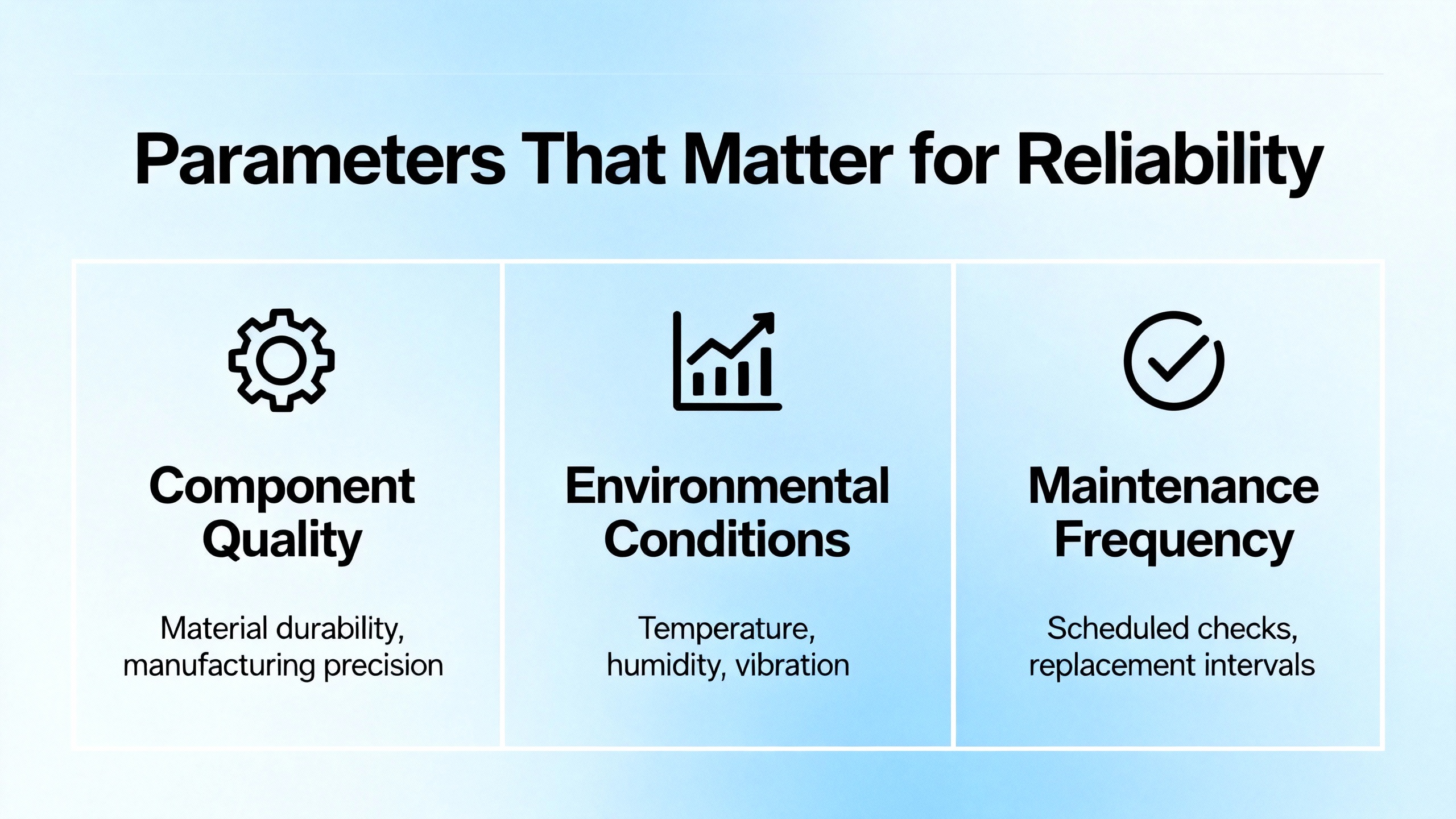
Parameters That Matter for Reliability
There is rarely a single magic setting that prevents trips, but certain parameters on the PF525 consistently move a system toward resilience when used correctly. The DC Bus Regulator (P041) suppresses overvoltage from regeneration and pairs well with a physical braking resistor when inertia is high. The Current Limit (P042) is your tool for avoiding nuisance overload trips during momentary spikes without risking the power section. Fault Masking (P050) can filter nonŌĆæcritical events that are expected during powerŌĆæup or certain transitions, but it must be used cautiously, with clear documentation, so genuine hazards are never muted. Auto Reset Attempts (P090) help a line recover from minor, fleeting events without operator intervention, but they are not a substitute for cause correction; if a drive keeps resetting, you still have a problem to fix.
In faultŌĆætoŌĆæfix tuning, a handful of parameter references show up repeatedly in successful resolves. For acceleration and deceleration behavior, pair P039 and P040 with the ramp profile group A442 through A446. If a system reports motor overload or moves sluggishly on low speed, verify P033 Motor Overload Current and A530 Boost rather than guessing at torque issues. When the drive complains of load loss, review A490 and A491 for level and time. After a parameter storage or checksum event, reset to defaults with P053 in a controlled manner and restore a recent backup rather than trying to type values from memory. Communication and safety mappings also direct outcomes. C125 can define what a PF525 does under communication loss, and t105 governs how the drive treats a Safety Open event; set them deliberately and test that they behave as intended.
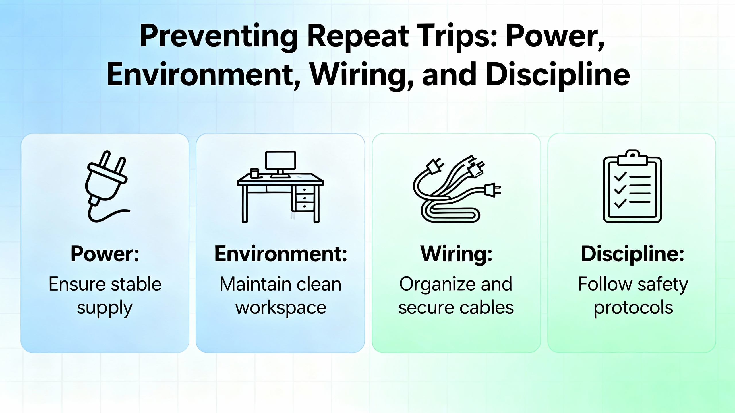
Preventing Repeat Trips: Power, Environment, Wiring, and Discipline
Four habits consistently separate stable lines from chronic trippers. Power quality must be treated as a system property rather than ŌĆ£someone elseŌĆÖsŌĆØ problem. If multiple large motors, welders, or highŌĆæinertia machines share a feed, stabilize the source with reactors or transformers and plan deceleration profiles that donŌĆÖt dump energy into the DC bus faster than the system can absorb it. Environment is not an afterthought. Drives fail early in hot, dusty enclosures. Clean filters, verify airflow, and maintain panel hygiene on a threeŌĆætoŌĆæsix month cadence, adjusting for seasonal heat. Wiring and grounding are part of control design. Use VFDŌĆærated shielded motor cable, ground the shield at one end (typically at the drive), route motor and control cables separately, and protect against abrasion that nicks insulation inside the motor junction box. Finally, practice operational discipline. Log faults with time and operating context, look for patterns like afternoon thermal peaks or startŌĆæofŌĆæshift voltage sags, and back up parameters regularly using Connected Components Workbench or the HIM keypad. Those small habits turn troubleshooting from guesswork into a short, repeatable checklist.
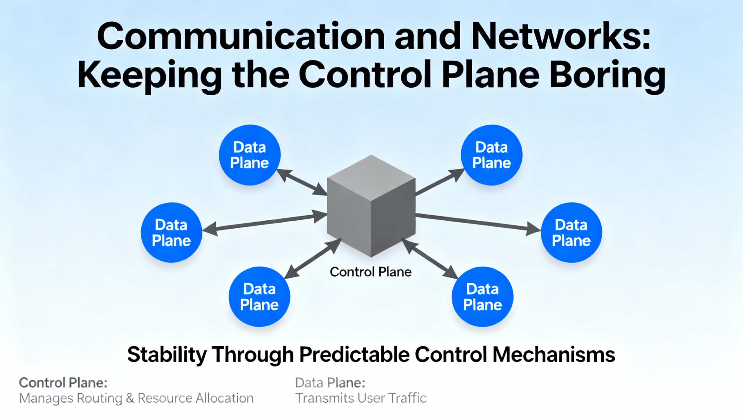
Communication and Networks: Keeping the Control Plane Boring
CommunicationŌĆærelated trips are among the most avoidable in modern plants. For PF525 adapters and PF527 integrated motion, most loss events trace to basic network hygiene. Use quality, shielded Ethernet cables in industrial runs, keep cable paths short and direct, and use switches rated for the environment and traffic patterns. Remove unnecessary devices that add jitter or processing delay, and physically separate signal from power wiring. In the PF525 family, DeviceNet Serial Interface and optionŌĆæcard losses clear once the wiring, addressing, and card seating are corrected. EtherNet/IP losses fall the same way, with IP alignment and switch health doing most of the work. On PF527 motion networks, alarms about late controller updates, clock skew, or sync faults tell you the plant network is overŌĆæbusy or underŌĆædesigned for deterministic traffic; fix the topology rather than masking the symptom.
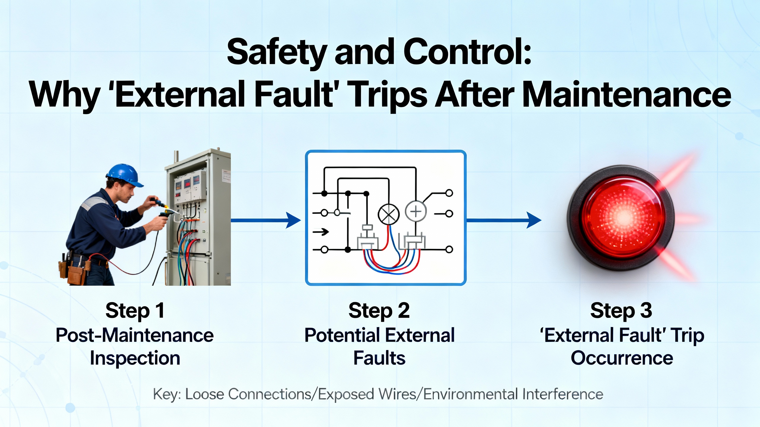
Safety and Control: Why ŌĆ£External FaultŌĆØ Trips After Maintenance
Two recurring confusions deserve attention. The first is the ŌĆ£external faultŌĆØ on a mapped digital input that shows up immediately after a retrofit or safety update. That trip is working as designed; either the safety relay is open, the input mapping was changed, or the wiring is wrong. The cure is to verify function assignment on the input, check the circuit wiring, and only bypass or reassign for testing when risks are mitigated. The second is ŌĆ£safety openŌĆØ on PF525, which is often a misconfiguration when the builtŌĆæin safety terminals are not used. Either install the jumpers correctly or configure t105 for the design case and test for safe behavior with your LOTO procedures. In neither case should the drive be coerced into running with safety inputs in an unknown state.
Repair or Replace: Drawing the Line
Some errors point to failing silicon rather than configuration, wiring, or environment. Industrial Automation Co. calls out a few PF525 fault families that, when recurring, are more costŌĆæeffective to resolve by replacement than by chasing ghosts. Power Unit Failure, Microprocessor Failure, and NonŌĆæRecoverable Error are in that group. If they surface after a clean power cycle with no obvious environmental cause and they return after a careful firmware flash, plan to replace the drive or control module. The fastest path back to production is often a swapŌĆæin with parameter restore from a recent backup, and then a bench evaluation of the failed unit by a qualified repair provider.
Field Notes: What Actually Fixes the Common Trips
Overvoltage during deceleration is among the most common preventable trips. I see it most often on large fans and conveyors with high inertia. The reliable fix is a softer decel profile paired with a braking resistor sized for the energy; enabling the DC Bus Regulator helps, but physics wins and the resistor does the heavy lifting. Undervoltage appears in plants where long cable runs and loaded feeders share space; tightening terminations and upsizing feeder gauge stop many nuisance trips. Ground faults rarely lie. If a PF525 flags a ground fault that only occurs under load, the insulation is breaking down. A megger test of the motor and cable will confirm it. Communication losses are usually housekeeping. Once the shop swaps in shielded patch cords, reseats option cards, corrects IP conflicts, and moves the Ethernet bundle off a hot power tray, the system goes quiet.

Pros and Cons of Common Tactics
AutoŌĆæreset is invaluable for fleeting disturbances, but overuse hides unstable conditions that return at the worst times. Use a small number of attempts and log every event. Fault masking avoids false positives during powerŌĆæup or transitions, but it is a scalpel, not a broom; mask only what you can justify in a hazard analysis. Shunt regulation and braking resistors are reliable at absorbing regenerative energy, yet they add heat and hardware; ensure your panel ventilation can handle the dissipation. Longer ramps reduce both overvoltage and overcurrent incidents, but they change machine cycle time; have production sign off on the profile. Upgrading Ethernet switches and cable to industrial grade costs less than a single afternoon of downtime; the only downside is the temptation to leave bigger topology problems unsolvedŌĆöfix the architecture, not just the parts.
Optional FAQ
Why do faults recur right after I clear them?
If a fault returns immediately after clearing, the cause is still present. For PF525, verify basic items in this order: input power level and balance, motor and control wiring integrity, realistic accel and decel settings, and thermal conditions inside the enclosure. If the event is communicationŌĆærelated, resolve IP addressing or cabling before the next enable. Only enable autoŌĆæreset after you have high confidence that the disturbance is transient.
How can I tell whether an overcurrent is wiring or load?
Start with wiring and insulation. Tighten terminations and megger the motor and cable. If the result is clean, reduce acceleration and torque limits and test with a knownŌĆægood motor on short leads. If the overcurrent disappears with the substitute motor, the original motor or cable is guilty. If it persists on the substitute, investigate the driveŌĆÖs power section.
What does ŌĆ£Decel OverrideŌĆØ mean on PF527 motion?
It means the drive limited deceleration to protect the DC bus. The cure is to handle regenerative energy safely by using shunt regulation, adding an external shunt, stabilizing the AC input, and lengthening motion profiles as required for energy balance.
Sources and Credibility
This article reflects fieldŌĆætested patterns consistent with authoritative material. The PF525 code behaviors and corrective actions mirror Industrial Automation Co. guides. PowerFlex 527 groupings and motionŌĆæspecific codes are drawn from UpFixŌĆÖs summarized fault notes. General VFD failure patterns and environmental best practices align with GES RepairŌĆÖs recommendations. Hardware overcurrent insights come from a PLCTalk thread on PF70 Fault 12. Thresholds and fault behavior for PowerFlex 700 are summarized from a widely circulated, textŌĆæextracted reference of Rockwell Automation documentation. When in doubt, always confirm against Rockwell Automation manuals for your exact model and firmware, because naming and numbering can differ across generations and configurations.
In short, treat fault codes as your driveŌĆÖs way of telling you what hurts. Listen, correct the cause, document what you changed, and your system will reward you with the only metric that matters in production: boring, predictable uptime.
As a power system specialist and reliability advisor, IŌĆÖm happy to help you translate a stubborn code into a stable system; tell me what fault youŌĆÖre fighting, and weŌĆÖll map the fastest, safest route back to runtime.
References
- https://fab.cba.mit.edu/classes/865.18/power/VFD.pdf
- https://fod.osu.edu/sites/default/files/div_40.pdf
- https://irtfweb.ifa.hawaii.edu/~tcs3/tcs3/Misc/CFHT/Dome_drive_upgrade/Rockwell%20Proposal-for%20reference-not%20chosen/motor%20controller/air%20cooled/Embedded%20EtherNetIP%20adapter/750com-um001_-en-p.pdf
- https://disclosures.myresearch.stonybrook.edu/COI/sd/Rooms/RoomComponents/LoginView/GetSessionAndBack?redirectBack=https%3A%2F%2Fcdn.prod.website-files.com%2F675d914cb9a91d0d7e43fabe%2F683748c32d8b585c97d3127b_suvagekozutatita.pdf
- https://www.plctalk.net/forums/threads/powerflex-70-hw-overcurrent-fault-12-what-is-the-common-reason-for-this-fault.134309/
- https://blog.upfix.com/allen-bradley-powerflex-527-fault-codes
- https://gesrepair.com/common-powerflex-vfd-issues-and-how-to-resolve-them/
- https://www.pesquality.com/blog/allen-bradley-powerflex-525-fault-codes
- https://www.powergearx.com/allen-bradley-powerflex-40-understanding-fault-codes-and-how-to-fix-them/
- https://www.precision-elec.com/powerflex-755-troubleshooting-fault-codes/?srsltid=AfmBOop4knGlaon2_4ExgWSXfbFhWbZ0I0puo7BKIgBrL7N0U1mPA8n6


 Videos
 News
News Applications


Leave Your Comment