ControlLogix controllers are rugged, but when a 1756 chassis throws codes at 2:00 AM the difference between a quick recovery and an extended outage is your ability to translate fault numbers into concrete actions. As a power system specialist and reliability advisor, I view Rockwell codes through a plant-operations lens: which ones point to power quality, which implicate I/O wiring or firmware hygiene, and which demand a network or security response. This guide consolidates what matters in the field, backed by reputable sources, and distills it into a plainŌĆæEnglish reference with practical fixes, not just definitions.
When I walk into an electrical room after a stop, I take the same route every time. I note LED patterns on the 1756 controller and ENxT modules, pull the exact fault and subcodes from Studio 5000, and correlate those with the observed plant condition and recent changes. Then I triage power and network fundamentals before diving into logic or module swaps. The reason is simple: most stoppages trace to supply irregularities, physical connections, or firmware incompatibilities, long before a CPU is truly ŌĆ£bad.ŌĆØ With that context, letŌĆÖs decode the codes.
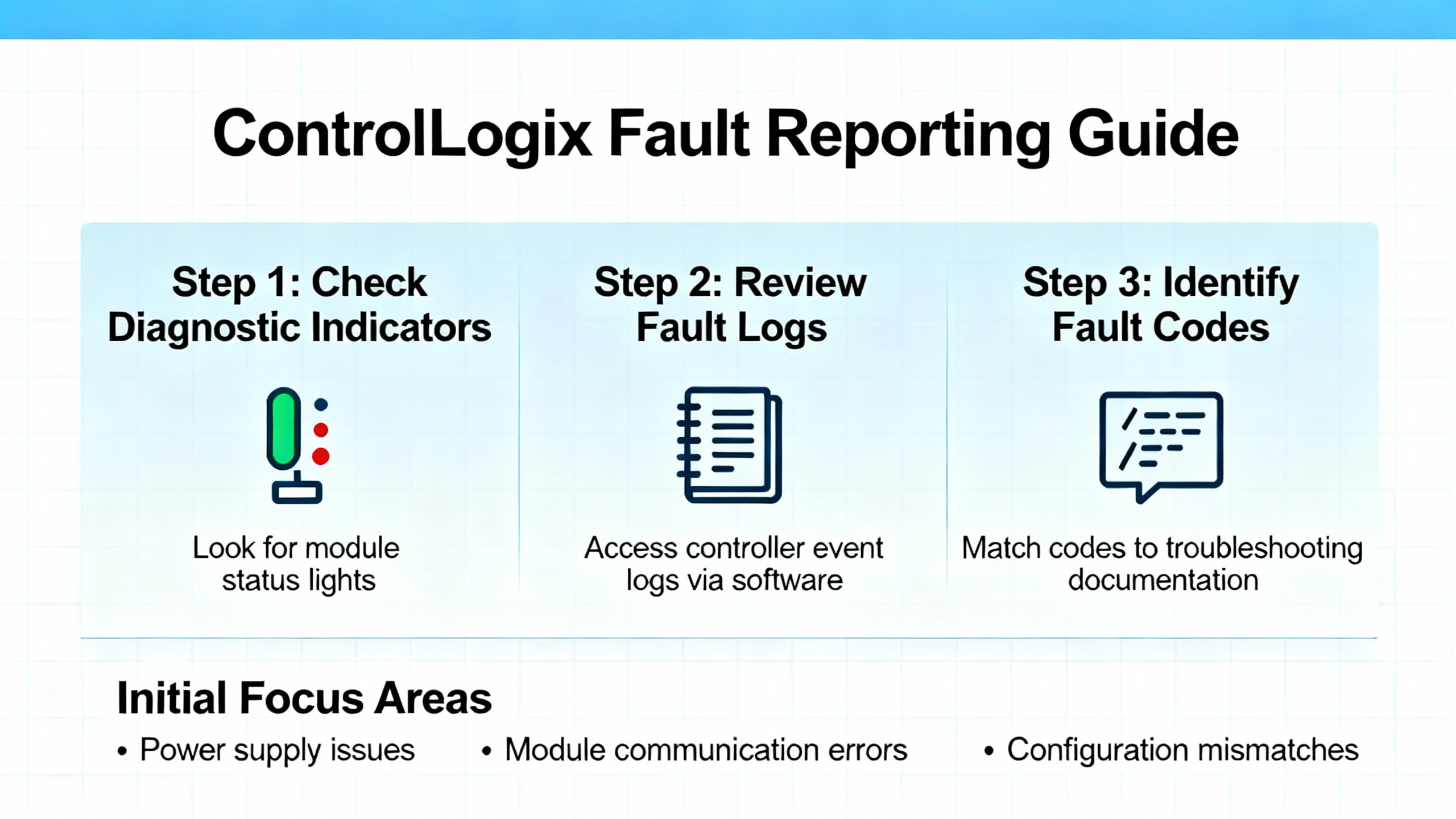
How ControlLogix reports faults and where to look first
ControlLogix distinguishes between major faults that halt execution, minor faults that log exceptions while the controller continues to run, and I/O faults tied to module or connection problems. Major faults stop the controller and often place outputs into a configured fault or program state. Minor faults set diagnostic flags and entries without halting tasks; they frequently capture events such as arithmetic overflows or conversion errors that your program can handle if you build the right fault routines. I/O faults arise when a module is removed, a connection times out, electronic keying mismatches, or a network path breaks.
The LED story still matters. In the field, RUN solid green means logic is executing, OK solid green means the controller or module is healthy, and red or flashing on OK or I/O indicators points to a fault condition. You can confirm details by going online with Studio 5000 to read the controller fault log and each moduleŌĆÖs properties. RockwellŌĆÖs diagnostics will show the fault group, the code, and any extended subcodes that tell you if this is an addressing error, a connection timeout, or an unavailable resource, among other categories. Industrial Automation Co. summarizes those indicators well, and it maps directly to what you see on a real chassis.
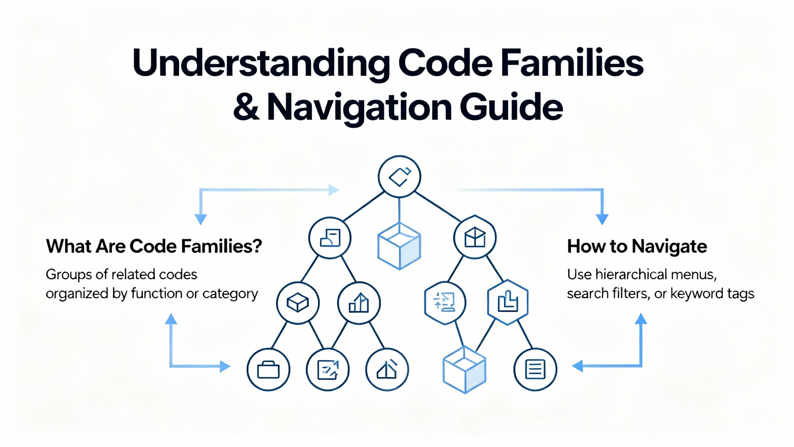
What the code families mean and how to navigate them
Beyond individual numbers, codes tend to cluster into families. Recognizing the family speeds your first move because it tells you whether to reach for a digital multimeter, a cable tester, or ControlFLASH.
| Code family (hex) | Typical meaning | Examples from field sources | Where to look next |
| 0x0xx | Node/network and device availability issues | Station offline, remote node missing, hardware fault indicators from VTScada help | Physical links, switch ports, IP conflicts, duplicate addresses, cabling continuity |
| 0x1xx | Addressing, symbol, and data type semantics | Illegal command or format, symbol not found, data type mismatch seen in VTScada and Manuals.plus | Tag names, path syntax, data types, array bounds, program structure |
| 0x2xx | Local communications, storage, or port problems | SD/serial port unavailable, illegal station address syntax per VTScada help | SD status, serial parameters, driver presence, controller storage health |
| 0x3xx | Sockets, CIP/TCP, and connection handling | Socket timeout or loss, CIP protocol error noted by VTScada | ENxT diagnostics, RPI alignment, connection counts, switch error counters |
In practice, extended error codes and the module or object reporting them are the breadcrumbs. Rockwell documentation notes that ŌĆ£extended error codesŌĆØ refine the root cause inside categories like connection failure or IOI syntax error. If you see those phrases in the Logix Designer diagnostics, follow the extended code trail to the appropriate manual entry.
A practical table of common ControlLogix codes and what to do next
The table below consolidates frequent codes reported across control rooms and repair benches, along with actions that have restored production in minutes rather than hours. The meanings come from recognized sources like Global Electronic Services, Manuals.plus, and VTScadaŌĆÖs AllenŌĆæBradley error reference.
| Code | Category | Meaning in plain language | First checks and rapid actions | Primary source |
| 0x04 | Program execution | Recoverable logic error such as divideŌĆæbyŌĆæzero | Open the reported rung, correct the operand or range, redeploy; validate with a small batch run | Global Electronic Services |
| 0x08 | Program execution | Watchdog timeout from excessive scan time or runaway logic | Profile task utilization, simplify heavy rungs, eliminate loops, consider increasing period on periodic tasks | Global Electronic Services |
| 0x0F | Memory | NonŌĆærecoverable memory error | Attempt firmware reflash; if persistent, prepare CPU replacement and restore from a verified backup | Global Electronic Services |
| 0x12 | Network/I/O | I/O timeout or lost contact with a module | Check field cabling, reseat the module, verify RPI and keying, inspect ENxT link status | Global Electronic Services |
| 0x1F | Configuration | Module configuration mismatch with controller | Align module definition and keying in Studio 5000, confirm firmware compatibility, then reŌĆæestablish the connection | Global Electronic Services |
| 0x80 | EtherNet/IP | EtherNet/IP timeout due to congestion or switch trouble | Check switch error counters, monitor traffic and packet loss, clear duplicate IPs, replace failing switch hardware if needed | Global Electronic Services |
| 0x88 | Network | Duplicate IP addresses on the network | Assign unique IPs, verify BOOTP/DHCP settings, and document the addressing plan | Global Electronic Services |
| 0x300 | Memory | Insufficient memory available | Remove unused routines and tags, trim trend data, or upgrade memory where supported | Global Electronic Services |
| 0x320 | Memory | Program corruption detected | Reload the project from a verified backup and validate checksums | Global Electronic Services |
| 0x700 | Motion | Axis fault, likely drive feedback or mechanical binding | Inspect feedback, wiring, and mechanical travel; clear binding before reset | Global Electronic Services |
| 0x730 | Motion | Excessive position error | Retune the axis and verify mechanical alignment and backlash | Global Electronic Services |
| 0x1000 / 0010 | Command/format | Illegal command or format from local processor | Confirm instruction and message structure; compare with device capabilities | Manuals.plus, VTScada help |
| 0x2000 / 0020 | Communications | Communication module not working | Reseat the ENxT, verify power and backplane, check module OK LED patterns | Manuals.plus |
| 0x3000 / 0030 | Remote node | Remote node missing, disconnected, or shut down | Verify cabling and power at the remote node, confirm addressing and path | Manuals.plus |
| 0x4000 / 0040 | Hardware | Processor connected but faulted | Read the controller fault log and subcodes, rule out power quality events, proceed to logic or firmware | Manuals.plus |
| 0x7000 / 0070 | Controller mode | Processor is in Program mode | Switch to Run or Remote Run once faults are cleared and safety interlocks validate | Manuals.plus, Industrial Automation Co. |
| F012 | Access | No access or privilege denied | Confirm credentials and access level; check file or object ownership flags in the environment | Manuals.plus |
| F013 | Data type | Data type requested does not match data available | Align instruction operands and tag types; adjust conversions explicitly | Manuals.plus |
| F014 | Parameters | Incorrect command parameters | Review parameter sets and lengths; consult module documentation for required fields | Manuals.plus |
| F015 | References | Address reference exists to a deleted area | Rebuild references or restore the data table; clean obsolete tags | Manuals.plus |
| F018 | Conversion | Data conversion error | Set explicit type casts and ranges to avoid overflows or truncation | Manuals.plus |
| 0x308 | CIP | CIP protocol error | Reduce packet size if necessary, validate path and IOI syntax, confirm compatibility | VTScada help |
| 0x070 / 112 | State | Processor in Program Mode | Verify intentional stop vs faultŌĆæforced stop; resume only after clearing underlying fault | VTScada help |
If a row includes both hexadecimal and decimal, it reflects the dual representations seen across tools and references.
A fast, structured workflow that avoids blind swapping
When alarms are blaring and maintenance wants to swap hardware, take two minutes to capture the exact code and subcodes, LED states, and operating context. That snapshot prevents circular troubleshooting and helps the next shift see patterns. I start with LEDs because they reveal whether the problem is controllerŌĆæwide or localized to a module or network segment. I go online with Studio 5000 to read fault history, module properties, and tag values. If the error references connection failure or path syntax, I investigate the physical layer next: field terminations, drops, trunk connections, and cabinetŌĆætoŌĆæcabinet links. Only after the power and network fundamentals check out do I edit logic or move to firmware.
Global Electronic Services notes that power issues account for a large majority of PLC failures. That aligns with what I see in cabinets on summer afternoons: brownouts, underŌĆærated supplies, and loose terminals masquerading as mysterious controller behavior. Before you replace a processor or ENxT, verify the DC supply is within the allowable 24 V DC band, tighten terminations, reseat field power feeds, and inspect surge devices. If your plant runs without a conditioned UPS frontŌĆæend, voltage excursions and transients can corrupt memory, crash modules, and trigger watchdog timeouts. A properly sized UPS and clean grounding reduce repeat faults dramatically.
Power quality and the ŌĆ£80 percentŌĆØ rule of thumb
Across plants of every size, power disturbances create intermittent and hardŌĆætoŌĆæreproduce faults. Guidance from Global Electronic Services highlights that roughly eight out of ten PLC failures trace back to power. In practice, that shows up as nonŌĆærecoverable memory errors after a dip, spontaneous reboots, and I/O dropout during motor starts. A simple discipline helps. Measure the supply at the terminals with a calibrated meter, confirm cabinet grounding and bonding, loadŌĆæcheck your power module against the chassis draw, and trend cabinet temperature. Add thermography during hot months to identify panels with restricted airflow or overloaded supplies. If the power frontŌĆæend is marginal, software fixes wonŌĆÖt hold.
Firmware and compatibility hygiene that keeps modules out of the red
Mixed or incompatible firmware is a quiet source of erratic behavior. ACS Industrial Services reminds teams to standardize controller and module firmware within a tested range and to use ControlFLASH or Studio 5000 tooling to update or roll back to a knownŌĆægood release. Flashing a single module above the controllerŌĆÖs supported profile can create configuration mismatches, ŌĆ£unrecognized moduleŌĆØ conditions, or recurring I/O timeouts. In the field, I maintain a oneŌĆæpage matrix of deployed firmware for the chassis and a small set of approved target versions. Before a planned upgrade, I stage the change in a test rack and record LED and diagnostics during a 30ŌĆæminute soak.
EtherNet/IP and the usual network culprits
Communication faults with codes such as 0x80 or ambiguous ŌĆ£connection failureŌĆØ often reduce to basic network hygiene. Industrial Automation Co. and RealPars both emphasize the same action list: ensure unique IP addresses, confirm subnets, monitor traffic for bottlenecks or excessive multicast, and use the right RSLinx or FactoryTalk Linx driver configuration. When discovery fails, verify the PC NIC is on the same subnet, enable continuous discovery in your tool, and clear stale device entries. Shaky patch panels, aging cables, and duplicate addresses can all produce timeouts that look like controller faults. When you fix them, the codes vanish without touching logic.
I/O module faults and updateŌĆærate side effects
I/O codes that point to timeouts, configuration mismatches, or ŌĆ£function not availableŌĆØ typically mean something changed in module parameters or wiring. Industrial Automation Co. shows how LED states on I/O cards quickly tell you whether the module is healthy, has an I/O data path problem, or has lost its network. Misconfigured update rates can appear as delayed data or intermittent faults, especially when update periods are set too slow for the process. Focus on the basics first: reseat the module, check field wiring for continuity, verify keying and module profile in Studio 5000, and confirm RPI values. If the module still faults, align firmware to the controllerŌĆÖs supported level and then retest.
SecurityŌĆærelated diagnostic flags deserve prompt attention
ClarotyŌĆÖs Team82 disclosed a vulnerability that allowed bypassing the Trusted Slot feature in certain ControlLogix chassis, prompting fixes documented in a CISA ICS Advisory. This matters because the symptoms may overlap with communication anomalies or unexpected controller behavior, and the remedy is to update to vendorŌĆæspecified versions. If your code drilldown shows securityŌĆærelated logs or if you run a 5580 class controller or affected Ethernet modules, work with operations to schedule a patch window that lands on the versions recommended by Rockwell. Keep security patching coordinated with production needs, and segment control networks so that only necessary sources can reach your ENxT or CPU.
Turning error codes into repeatable recovery: what the data says
Pure troubleshooting skill is necessary, but process prevents repeat failures. Global Electronic Services and other field reports reinforce disciplines that pay for themselves: log codes with date and operating context, keep verified offline backups aligned to firmware levels, and share fault histories between shifts to surface recurring patterns. In one audit noted by a thirdŌĆæparty repair shop, nearly half of supposedly failed modules were actually misconfigured. That ratio reflects what I see when teams jump to replacement before checking wiring, firmware alignment, and keying. Your first response to a code should be to gather context and validate fundamentals; your second should be to update documentation with what you learned.
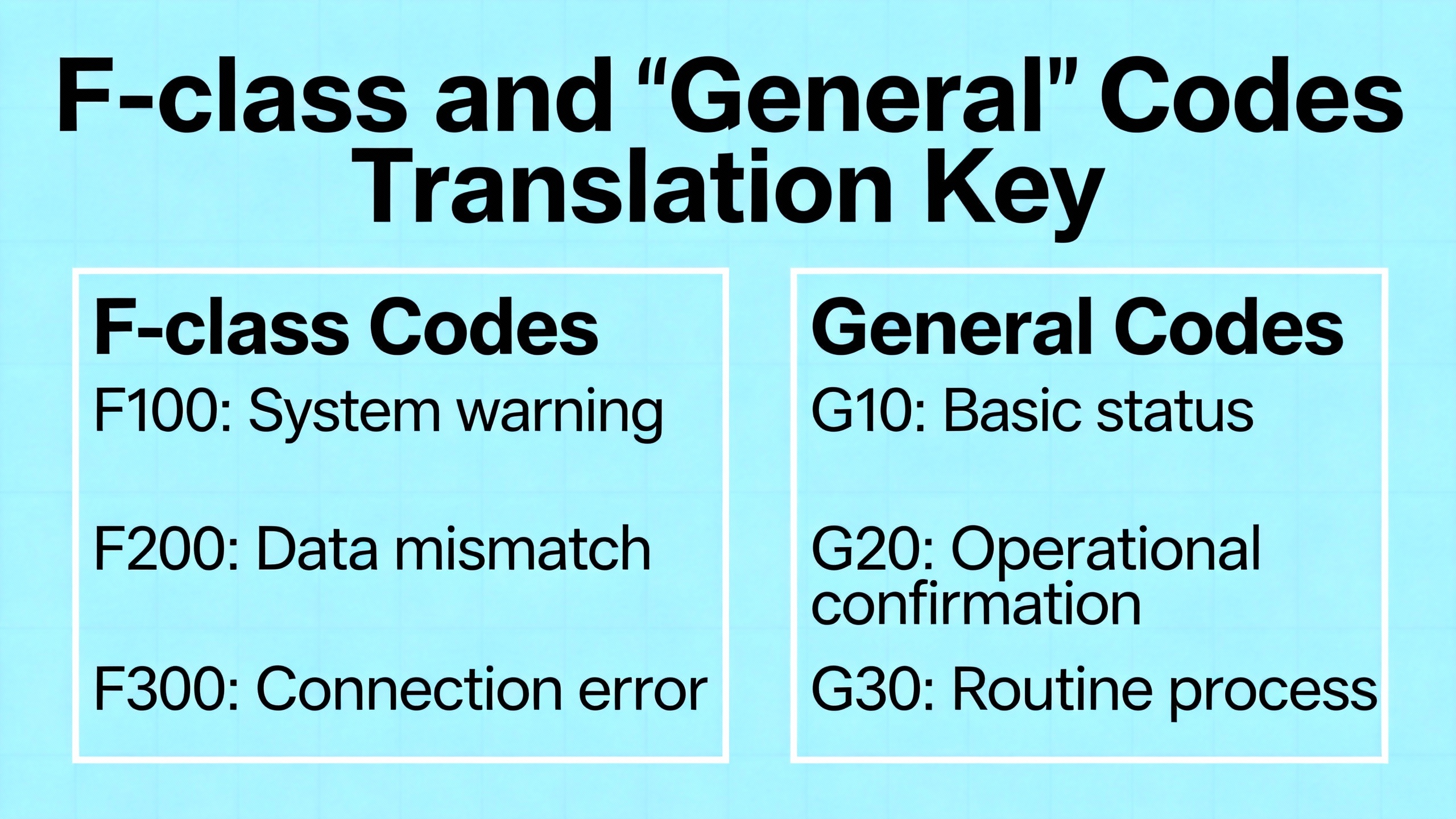
A concise translation key for frequent FŌĆæclass and ŌĆ£generalŌĆØ codes
When Studio 5000 surfaces FŌĆæclass diagnostic codes, your next move is often in the data type or addressing layer. These entries, drawn from Manuals.plus and VTScadaŌĆÖs published references, summarize the most common translations you will use during a live incident.
| Code | Meaning in the vendor reference | Practical interpretation |
| F001 | Processor incorrectly converted the address | Object path or address resolution failed; verify IOI syntax and tag structure |
| F002 | Incomplete address | The message or instruction lacks a required path element; complete the address segments |
| F003 | Incorrect address | Destination is wrong or invalid for the target device; confirm structure and scope |
| F004 | Illegal address format, symbol not found | Typo or missing symbol; correct tag naming or scope |
| F005 | Illegal symbol format or length | Symbol violates device limits; shorten or correct the symbol |
| F006 | Address file does not exist in target | Data table or object missing; create or point to the right object |
| F007 | Destination file too small | Buffer or array size insufficient; resize or change transfer length |
| F008 | Cannot complete request | Stop conditions changed or resource not available; retry after stabilizing state |
| F009 | Situation changed during multipacket operation | Dynamic condition altered the transfer; pause process, retry in a quiet state |
| F00B | Memory unavailable | Resource exhausted; free memory or reduce data footprint |
| F00D | Privilege error; access denied | Insufficient rights; authenticate with proper level |
| F010 | Command cannot be executed | Instruction invalid in current mode; check controller and module state |
| F011 | Overflow; histogram overflow | Arithmetic or counter exceeded capacity; add range checks |
| F012 | No access | Locks or ownership flags block the operation; close conflicting sessions |
| F013 | Data type mismatch | Cast or change operands to the supported type |
| F014 | Incorrect command parameters | Correct parameter values and lengths |
| F015 | Address reference to deleted area | Remove stale references or restore missing data |
| F018 | Data conversion error | Review implicit conversions; use explicit moves with size checks |
| F01C | Duplicate label | Ensure unique symbol names in scope |
| F01D | File owner active or program owner active | Someone is editing or downloading; coordinate access |
For controller and module state codes that appear as decimal or hex pairs, translations such as ŌĆ£processor in Program mode,ŌĆØ ŌĆ£communication module not working,ŌĆØ or ŌĆ£remote node missingŌĆØ indicate whether you need to change the controller mode, reseat a module, or inspect remote power and network status. References from Manuals.plus and VTScadaŌĆÖs error library align closely with what Studio 5000 shows.
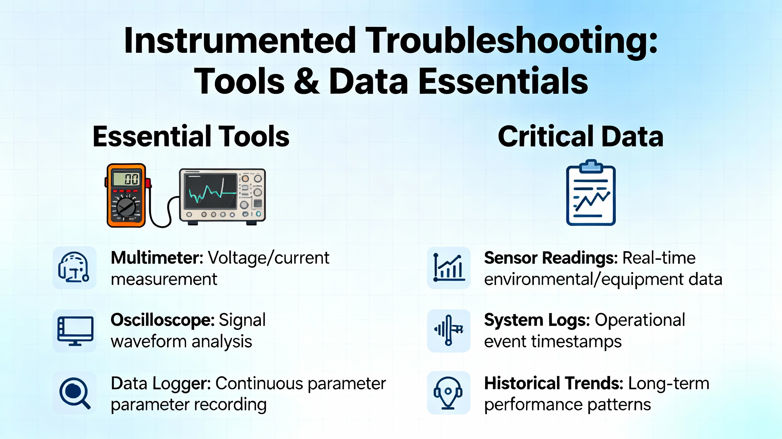
Instrumented troubleshooting: tools and data you should always have
Diagnostics are faster when your kit and software are ready. A digital multimeter validates supply health and ground, a network cable tester eliminates bad patch leads, and a laptop with current Studio 5000, ControlFLASH, and Linx drivers lets you go online to read codes and reflash when needed. Thermal imaging exposes enclosure heat stress that often correlates with nuisance faults during July afternoons. On the software side, RealPars explains how discovery settings in Linx affect online connectivity, while Maple Systems demonstrates how dedicated diagnostics views illuminate moduleŌĆælevel error states with clear visual indicators. These small details cut minutes from every incident.
Prevention beats heroics: power, firmware, and disciplined change
Your mean time between faults is largely a function of three habits: stable power and grounding, aligned firmware and profiles, and disciplined configuration management. A clean, rightŌĆæsized UPS frontŌĆæend with proper bonding will erase many intermittent errors you cannot reproduce on the bench. A firmware matrix and controlled upgrades eliminate ŌĆ£unrecognized moduleŌĆØ surprises. And versioned backups with labeled spares turn a single bad module into minutes of downtime instead of hours. The same sources that catalog error codes emphasize logs, backups, and training. Those are the lowŌĆæcost levers that move reliability in the real world.
A short FAQ to clarify highŌĆæleverage questions
When should you reset a controller after a major fault versus fixing the root cause first? The reset is appropriate only after you have captured the code, verified power and network health, and corrected the condition that caused the stop, such as bad operands or a disconnected I/O path. Clearing a major fault without addressing cause invites the same stop under load.
What is the practical difference between a watchdog timeout and a data type overflow? A watchdog timeout tells you the task exceeded its allowed time slice and indicates logic timing or task configuration issues. A data type overflow tells you an operation exceeded operand capacity and points to range checks and explicit data type choices. The former is a scheduling and load topic; the latter is primarily programming hygiene.
How should you handle recurring memoryŌĆærelated codes such as insufficient memory or program corruption? Remove unused routines and tags, reduce trend history, and validate your backup integrity. If nonŌĆærecoverable memory errors persist after a reflash, plan a controlled controller replacement and full restore. Both Global Electronic Services and Rockwell documentation point to memory management and verified backups as the durable remedy.
Conclusion
A ControlLogix code is a clue, not a verdict. The fastest recoveries happen when teams translate faults into the physical or configuration layers they represent, then validate the simple things first: power, wiring, addresses, update rates, and firmware alignment. From there, logic and motion tuning are straightforward. Keep a concise matrix of your common codes and a oneŌĆæpage triage routine at the panel door, and your 2:00 AM stops will turn into short pauses rather than long outages. If you want a second set of eyes on hardŌĆætoŌĆæreproduce stops, IŌĆÖm happy to review your fault histories and help close the loop with power conditioning, firmware hygiene, and network hardening that deliver lasting uptime.

Sources referenced
Rockwell Automation documentation on faults, I/O error codes, and controller diagnostics; Industrial Automation Co. field guides on ControlLogix troubleshooting; ACS Industrial Services repair guidance on firmware compatibility; Global Electronic Services code explanations and reliability practices; VTScadaŌĆÖs AllenŌĆæBradley error mapping; RealPars connectivity tips for Linx drivers; Maple Systems diagnostics walkthrough; CISA advisory and Claroty Team82 research on Trusted Slot security.
References
- https://www.plctalk.net/forums/threads/1756-ob32-issues.138237/
- https://gesrepair.com/troubleshooting-controllogix-plc-failures-common-causes-and-fixes
- https://manuals.plus/m/cae2983056ae3a7aef38bc893f3fec1817b74ce3c4e938d484d43aa54895026e
- https://library.e.abb.com/public/1f7e360e8e964f558c5af527d2cb1624/LVD-EOTN109U-EN.pdf
- https://blog.acsindustrial.com/allen-bradley-repairs/3-tips-for-troubleshooting-common-issues-in-allen-bradley-controllogix/
- https://media.distributordatasolutions.com/Rockwell/files/File_ControlNet_Network_Media_1756-UM001_EN_1.pdf
- https://industrialautomationco.com/blogs/news/navigating-module-faults-and-troubleshooting-in-compactlogix-5370-controllers-an-in-depth-guide?srsltid=AfmBOopJpFoqDE_PC-f1c0lny2nLJZ0no_S_-UkfbG4QApNX-VwdOtxZ
- https://www.scribd.com/document/726952249/ControlLogix-Fault-Codes
- https://www.ubestplc.com/blogs/news/allen-bradley-1756-controllogix-module-troubleshooting-guide-how-to-quickly-identify-and-resolve-hardware-failures?srsltid=AfmBOoobbc34L4qeCSRQtK39EkYFuZA-iuVbUScSYZqzfUUpX2RSqOwZ
- https://cdn.automationdirect.com/static/manuals/ea9rhmim/appxa.pdf


 Videos
 News
News Applications


Leave Your Comment