Keeping production moving when a drive trips is a reliability problem as much as it is a controls problem. As a Power System Specialist & Reliability Advisor, I approach PowerFlex troubleshooting the same way I approach power protection and UPS design: stabilize the source, remove noise from the signal path, respect thermal limits, and close the loop with repeatable settings and records. This guide distills fieldŌĆæproven methods and OEM guidance for PowerFlex 4/40/40P, 520ŌĆæSeries (523/525/527), and architectureŌĆæclass families (700/750/753/755), blending practical steps with the context you need to decide when to repair, when to reŌĆæparameterize, and when to replace. Throughout, I reference reputable sources such as Rockwell Automation user manuals, Industrial Automation Co., Global Electronic Services, HESCO, UpFix, OxMaint, Precision Electronic Services, and Wireless Telemetry.
How PowerFlex Faults Behave and Why That Matters
A fault is a protective trip that stops the inverter to prevent damage. On the PowerFlex platform, faults, alarms, inhibits, and exceptions mean different things. Faults halt output until the root cause is resolved and the drive is reset. Alarms warn about conditions that merit action but can be nonŌĆælatching. Safety inhibits, including Safe Torque Off and Axis Enable paths, intentionally disable the power structure and will not reset until the safety chain is healthy. Some faults are autoŌĆærecoverable after conditions normalize; others require corrective action plus a manual reset or power cycle. That distinctionŌĆöautoŌĆæreset versus nonŌĆæresettableŌĆödrives your triage plan.
Before clearing any code, capture the exact fault number and message and note the operating state when it occurred. I ask technicians to record input voltage, bus voltage, current, commanded speed, temperature indications, and whether the event struck during start, acceleration, steady state, or deceleration. This small discipline prevents erasing the evidence you need for root cause analysis.
Practical resets include the HIM keypad Stop/Reset, cycling input power, assigning a digital input to Fault Reset, or issuing a reset over communications. If a fault recurs immediately after reset, stop the reset attempts. Isolate variables; if the mechanism allows, decouple the motor from the load and test unloaded. In my experience, ŌĆ£reset stormsŌĆØ that skip root cause diagnosis can escalate from nuisance trips to hardware damage.
Always respect lockout/tagout, allow the DC bus to discharge, and use the appropriate PPE when inspecting or servicing the drive.
A Quick, Reliable Triage Workflow
PowerFlex drives supply highŌĆævalue diagnostics. Use them, but start with fundamentals. Verify the supply and phase balance, confirm terminations are tight, and confirm the driveŌĆÖs nameplate and motor parameters match. Review acceleration and deceleration ramps, current and torque limits, and confirm the motorŌĆÖs fullŌĆæload amps, base speed, and voltage class are correct in parameters. Inspect motor and control wiring for loose, frayed, or misŌĆæterminated conductors. Look for load binding or jams and confirm fans and ventilation are unobstructed. Only then move to codeŌĆæspecific steps, firmware checks, and module reseats.
Common Faults, Meanings, and FieldŌĆæProven Actions
The following table synthesizes common PowerFlex faults reported across 520ŌĆæSeries and 750ŌĆæSeries families and the corrective actions that consistently shorten downtime. Use modelŌĆæspecific manuals from Rockwell Automation for full details.
| Code | Fault name | What it indicates | First actions that work in practice |
| F003 | Power Loss | Input AC loss or singleŌĆæphase condition under load | Monitor line stability, check fuses and feeders, reduce load and recheck source quality |
| F004 | Undervoltage | DC bus below minimum from sags or interruptions | Stabilize the source, tighten terminations, consider a line reactor if long runs cause dips |
| F005 | Overvoltage | DC bus above maximum, usually regenerative energy on decel or line surges | Lengthen decel time, enable bus regulation, add a properly sized braking resistor; investigate upstream surges |
| F006 | Motor Stalled | Commanded ramp cannot be achieved | Increase acceleration time, reduce mechanical load, look for binding or jams |
| F007 | Motor Overload | Motor current exceeds protection threshold | Verify motor FLA parameter and boost settings, reduce load, ensure alignment and lubrication |
| F008 | Heatsink Overtemp | Power section overheated | Clean heatsink fins and vents, verify fan operation, improve ventilation or ambient cooling |
| F009 | Control Module Overtemp | Control electronics too hot | Improve airflow inside the enclosure, reduce ambient heat, confirm enclosure fans operate |
| F012 | Hardware Overcurrent | Current exceeded hardware limits | Reduce load and spikes, review boost and DC brake settings, inspect motor leads for shorts |
| F013 | Ground Fault | Current to ground on the output path | Megger the motor, inspect insulation and cable shields, correct grounded conditions |
| F015 | Load Loss | Output torque fell below threshold for too long | Inspect couplings and belts, confirm setpoints, adjust loadŌĆæloss level and timing parameters |
| F059 | Safety Open | Safety inputs not satisfied | Verify STO and safety terminal wiring/jumpers and safety device states before enabling |
| F064 | Drive Overload | Inverter exceeded its thermal rating | Reduce load, extend acceleration time, assess whether the drive is undersized |
| F070 | Power Unit Failure | Power section fault | Confirm ambient and cooling, power cycle once; if it persists, plan for replacement |
| F071 / F072 / F073 | DSI / Option Card / Embedded EtherNet/IP Loss | Communications path down | Check cables and IP settings, resolve duplicate IPs, reseat option cards, confirm switch health; set appropriate comm loss action |
| F081ŌĆōF083 | Communication Loss (internal/external) | Interruption between modules or adapters | Inspect grounding/shielding and reseat modules; replace damaged media |
| F091 | Encoder Loss | Missing or noisy feedback signal | Inspect encoder wiring, shields, and connectors, verify DIP switch alignment, replace encoder if needed |
| F048 | Parameters Defaulted | Values reset to defaults | Reenter required parameters or restore from backup, then clear and test |
| F100 / F101 | Parameter Storage / Checksum Error | Parameter memory corrupted | Reset to defaults, reprogram from backups, then validate functions |
| F105ŌĆōF109 | Module Mismatch / Connection Error | Control/power module recognition issue | Verify correct module pairing, reseat, power cycle, replace if mismatched |
| F114 | Microprocessor Failure | Internal CPU fault | Power cycle and retest; persistent faults point to replacement |
| F125 / F127 | Flash Update Required | Firmware corrupt or mismatched | Perform a proper firmware update using the recommended Rockwell procedure |
| F126 | NonŌĆæRecoverable Error | Critical internal error | Clear or power cycle; recurrence supports a replacement decision |
When you see a ŌĆ£Decel OverrideŌĆØ behavior under heavy regeneration, remember that the drive is protecting the DC bus by limiting deceleration. Remove ŌĆ£Adjustable FreqŌĆØ overrides where inappropriate, use a shunt regulator or braking package, stabilize AC input, and perform a controlled reset afterward.
Power Quality, DC Bus Behavior, and Regeneration
Overvoltage faults commonly occur during aggressive deceleration on highŌĆæinertia loads. The energy going back into the DC bus has to go somewhere. In practice, I resolve most regenerationŌĆærelated trips by lengthening the deceleration time, enabling the bus regulator, and adding a correctly sized dynamic braking resistor. On applications with repeated long decels or frequent stops, an external shunt or capacitor module may be warranted. Where sags, swells, or transient events dominate, a line reactor, surge protection at the switchboard, or even an isolation transformer or UPS can stabilize the input and protect the drive, as echoed by UpFix and other repair sources.
Undervoltage faults expose weak feeders and loose terminations. Verify phase balance, feeder lengths, and wire gauge. On long runs, upsizing cable and installing an input reactor often removes the pattern of nuisance undervoltage trips that only appear during shift changes or large motor starts in adjacent areas.
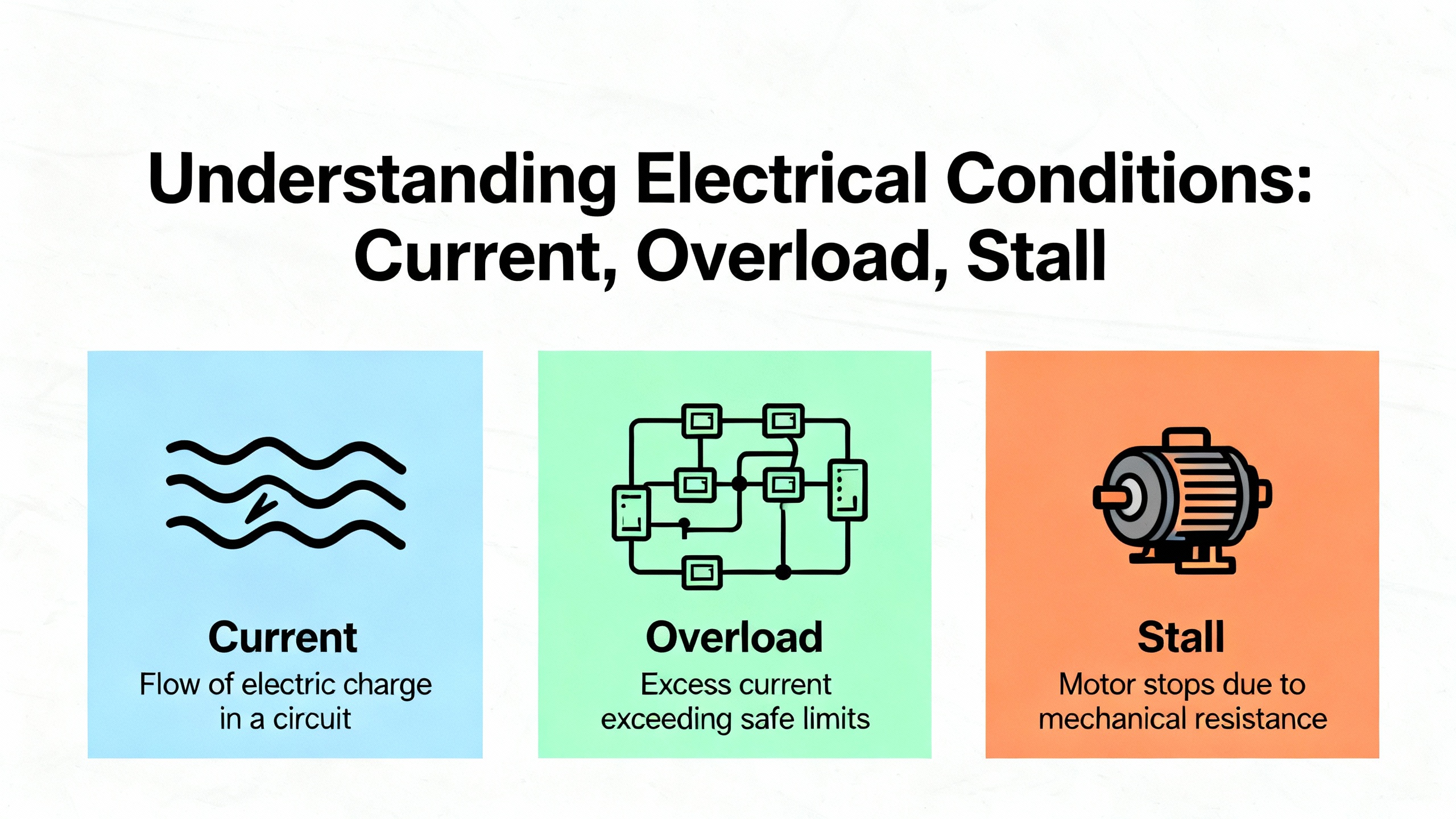
Current, Overload, and Stall Conditions
Hardware overcurrent trips are often mechanical in origin. Binding, misalignment, or load spikes show up electrically as abrupt current peaks. Increasing acceleration time, checking boost and DC brake settings, and confirming drive and motor sizing can restore reliable starts. A ŌĆ£Motor OverloadŌĆØ trip indicates the motorŌĆÖs thermal model or sensor is over threshold; confirm the motor FLA and base speed values in parameters and correct any overŌĆætensioning, jammed material, or process setpoints driving the excess torque. On the 527 family, overspeed and thermal capacity defaultsŌĆö590 Hz for overspeed and 110% for thermal capacity per UpFixŌĆöcan be tuned to match your mechanical design and safety constraints, then locked down in your change control system.
When a conveyor refuses to ramp without tripping, decouple the motor, verify the drive runs unloaded, and then methodically reintroduce the load. I have seen more downtime from a seized coupling and clogged pump than from any firmware bug.
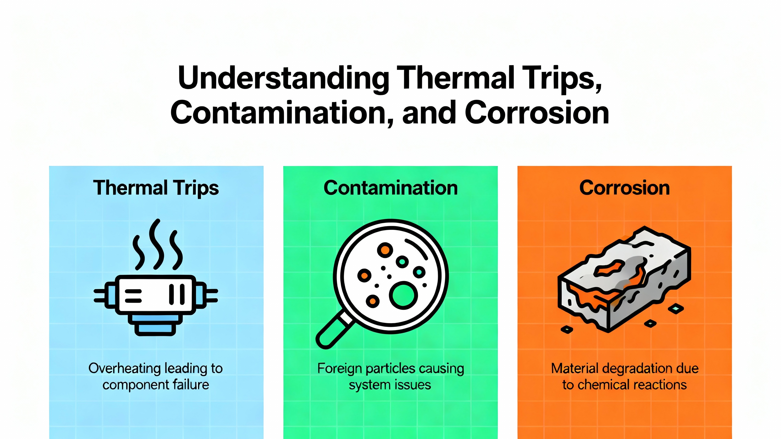
Thermal Trips, Contamination, and Corrosion
Overheating is a recurring root cause across brands and families. Heatsink and controlŌĆæmodule overtemperature faults spike in dusty, oily, or hot enclosures. Clean heatsinks and fans with appropriate air pressure, replace seized or noisy cooling fans, and maintain unobstructed airflow. The enclosureŌĆÖs ambient may require ventilation or air conditioning to keep electronics in a healthy range.
Contamination and corrosion produce stray currents and sensor drift. Precision Electronic Services highlights how conductive dust, oil, or moisture can cause controlŌĆæboard overtemperature or imbalances, and how oxidation of metal at elevated temperatures degrades PCBs. Tactics that work include isolation from contaminants, sealed housings, dehumidification in humid zones, andŌĆöin intermittentŌĆæduty areasŌĆöensuring cooling hardware does not induce condensation during idle periods. If powerŌĆælayer interface boards indicate persistent overtemperature or bus faults, and the environment audit confirms high risk, plan corrective maintenance and consider board replacement.
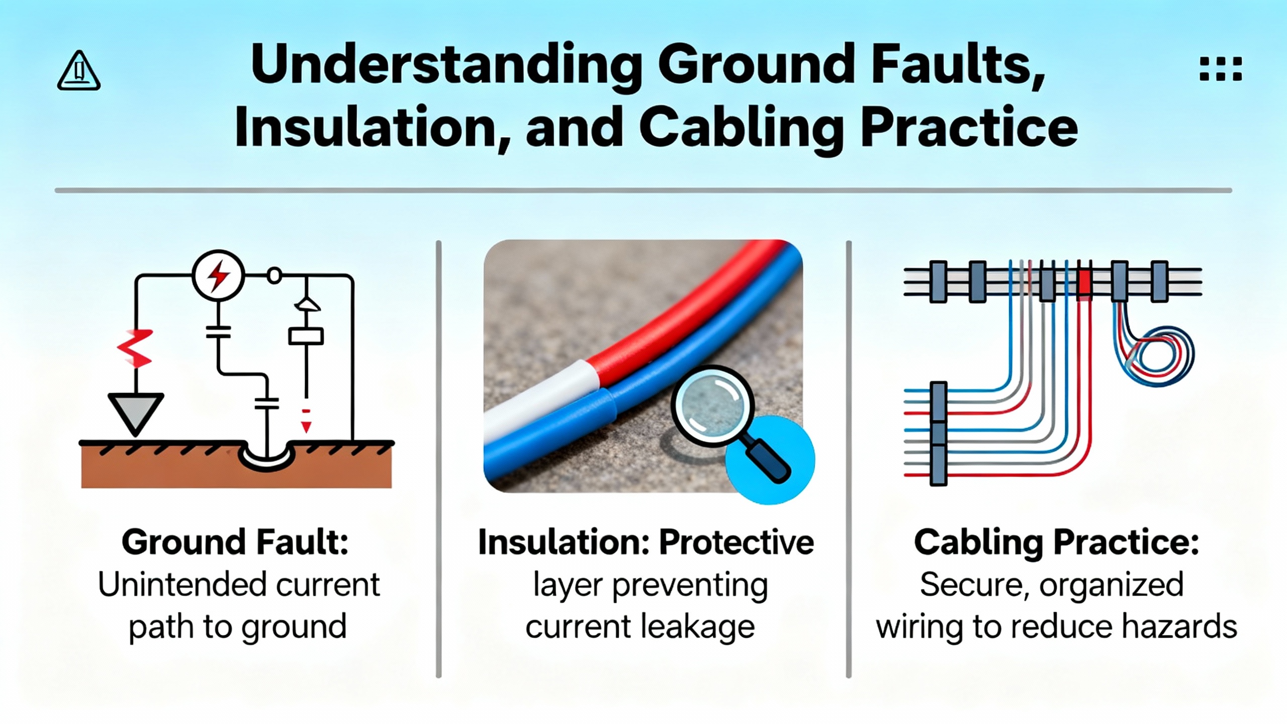
Ground Faults, Insulation, and Cabling Practice
Ground fault and phaseŌĆætoŌĆæphase faults demand a measured electrical response. Perform insulation resistance testing on the motor and cable, inspect for abrasion in conduit and at glands, and reŌĆæterminate with VFDŌĆærated shielded cable. Ground the shield at the drive end and segregate motor leads from lowŌĆælevel control wiring to avoid induced noise and false trips. Wireless TelemetryŌĆÖs quickŌĆæreference for 753 faults and GES repair guidance converge on the same point: do the simple checks thoroughly, because they resolve most protection trips without opening the backplane.
Communications, Safety, and Feedback Pathologies
Loss of DSI or embedded EtherNet/IP connectivity shows up as communication loss faults and stalled processes. In the field, the most common culprits are cable fatigue, duplicate IP addresses, stressed daisyŌĆæchain topologies, and unmanaged switches with poor handling under bursts. Confirm addressing and subnet masks, reseat or replace option cards and patch leads, and move to shielded, highŌĆæperformance managed switches where jitter and clock skew are out of bounds. When available, set a wellŌĆæconsidered communication loss action so that a transient outage does not create a hardŌĆætoŌĆærecover process state.
Safety Open and Aux Input Trip conditions are designed to be stubborn. Verify the status of safety relays, STO channels, enable inputs, and the entire interlock chain endŌĆætoŌĆæend. Do not bypass safety to clear a trip; use the drive indicators and the safety device documentation to restore the intended state. For feedback issues, including encoder loss, examine the encoder housing, connectors, shielding, and DIP switch settings on compatible encoder cards such as the 25ŌĆæENCŌĆæ2/B. Mechanical vibration and loose hardware are frequent culprits in intermittent A/B channel loss, especially on hoists and indexers.
Firmware, Storage, and Module Integrity
Parameters defaulted, storage errors, and ŌĆ£flash update requiredŌĆØ faults are systemic problems. If Reset to Defaults is needed, reprogram your knownŌĆægood baseline and then restore from backups. The surest way to take the pain out of these events is to keep parameter backups via Connected Components Workbench or the HIM, and to align firmware across drives and modules under change control. Microprocessor and powerŌĆæunit failures are clear decision points; repeated F070, F114, or nonŌĆærecoverable F126 events generally justify replacement over extended troubleshooting, a view shared by Industrial Automation Co. and repair specialists.
Reset and Recovery, Without Losing the Plot
Once you correct the cause, you can clear soft faults or issue a full drive reset. Power cycling is justified after verifying that you will not erase critical data without a backup, especially when you suspect firmware or memory involvement. The recovery run should be a lowŌĆærisk jog while you monitor bus, current, temperature, network status, and safety bits. If the fault recurs at the same operating point, respect the evidenceŌĆödonŌĆÖt override it.

Preventing Recurring Trips
Most repeat trips die under a regimen of orderly maintenance and power hygiene. Keep heatsinks and fans clean, replace fans on condition, and confirm enclosure ambient stays in spec during the heat of the day. Protect the input with surge protection and consider input reactors where supply impedance or harmonics are troubling. Review acceleration/deceleration and current limits for realism and revisit any ŌĆ£temporaryŌĆØ settings applied during commissioning. Separate power and signal wiring, use VFDŌĆærated shielded cable on motor leads, and document cable runs and termination methods. Keep firmware consistent across like drives, log fault histories with operating context, and stabilize your network plant with thoughtful topologies and good switches. Finally, keep parameter sets backed up and, for critical spares, preŌĆæstage configurations so swapping hardware does not become a long reprogramming exercise.
Migration and Lifecycle: Planning Around June 2025 and Beyond
AllenŌĆæBradley PowerFlex 4/40/40P reach official endŌĆæofŌĆælife in June 2025. Those legacy drives are still on fans, pumps, conveyors, and compressors across plants, so the lifecycle impact is broad. Modern replacements in the 520ŌĆæSeries differ in footprint, terminal positions, and communications. Older units rely on DSI while newer platforms standardize on EtherNet/IP, which means nonŌĆæEthernetŌĆæready systems may need panel rework and networking upgrades. HESCO recommends performing an Installed Base Evaluation to inventory what is in the field and to deŌĆærisk migrations.
Scheduling upgrades in planned downtime windows and preŌĆæstaging parameters are the fastest levers you have to minimize disruptions. Using Connected Components Workbench to preload parameters and, when possible, exporting from older drives with DriveTools SP shortens commissioning and reduces errors. If your distributor offers loaner drives, that is an underrated fallback to safeguard production while you resolve a stubborn commissioning fault.
On replacements, the lowest upfront cost is not always the least expensive path over the next five years. The 525 is a preferred upgrade path in many plants, in part because Ethernet diagnostics, Safe Torque Off, and longer lifecycle support improve reliability and maintainability. Evaluate total cost of ownershipŌĆöpanel changes, engineering time, networking, training, and future supportŌĆörather than drive price alone. In my experience, paying for network visibility and safety today saves multiples in avoided unplanned downtime, especially where diagnostics and predictive maintenance are on your roadmap.
Migration Planning Essentials at a Glance
| Topic | Practical guidance grounded in field results |
| Lifecycle and dates | Recognize official endŌĆæofŌĆælife dates such as June 2025 for PowerFlex 4/40/40P and plan accordingly |
| Physical and I/O | Confirm footprint, conduit entry, terminal layout, and I/O count against existing panels to avoid surprises |
| Networks | Map DSI versus EtherNet/IP; plan adapters and switch capacity; resolve IP addressing and VLANs before swap |
| Safety | Verify STO and interlock wiring plans and functional safety documentation if you are adopting STO |
| PreŌĆæstaging | Load parameters with Connected Components Workbench, and export baseline configurations from retiring drives |
| Downtime | Align installations with maintenance windows; keep a tested fallback; consider loaners to protect production |
| TCO | Weigh engineering hours, panel rework, training, and diagnostics against a purely upfrontŌĆæprice decision |
Care and Buying Tips That Keep You Out of Trouble
Treat a VFD as part of a system. Size the drive for the true mechanical load and duty cycle, not for an optimistic brochure point. Confirm motor data, FLA, base speed, and torque characteristics are set correctly. Specify braking hardware when deceleration profiles demand energy handling. Favor drives with integrated safety if your application warrants it, and align network capabilities with your plantŌĆÖs standards so diagnostics and remote support are firstŌĆæclass citizens from day one. For new purchases, ask for parameter preŌĆæload service and keep spares with firmware matching your installed base, along with backedŌĆæup parameter sets, so you can replace hardware without stretching a short outage into a shift.
Environment matters. If your enclosures live in dusty, humid, or hot areas, consider sealed housings, dehumidification, and rightŌĆæsized cooling. Fans are consumables; plan to inspect and replace them before they seize. For cable runs, use VFDŌĆærated shielded cable and preserve separation between power and control to protect signal integrity. And because the cleanest fixes are procedural, keep a running log of fault history, conditions at the moment of trip, and corrective actions taken; patterns will emerge that guide more proactive maintenance.

When Repair Makes Sense and When Replacement Wins
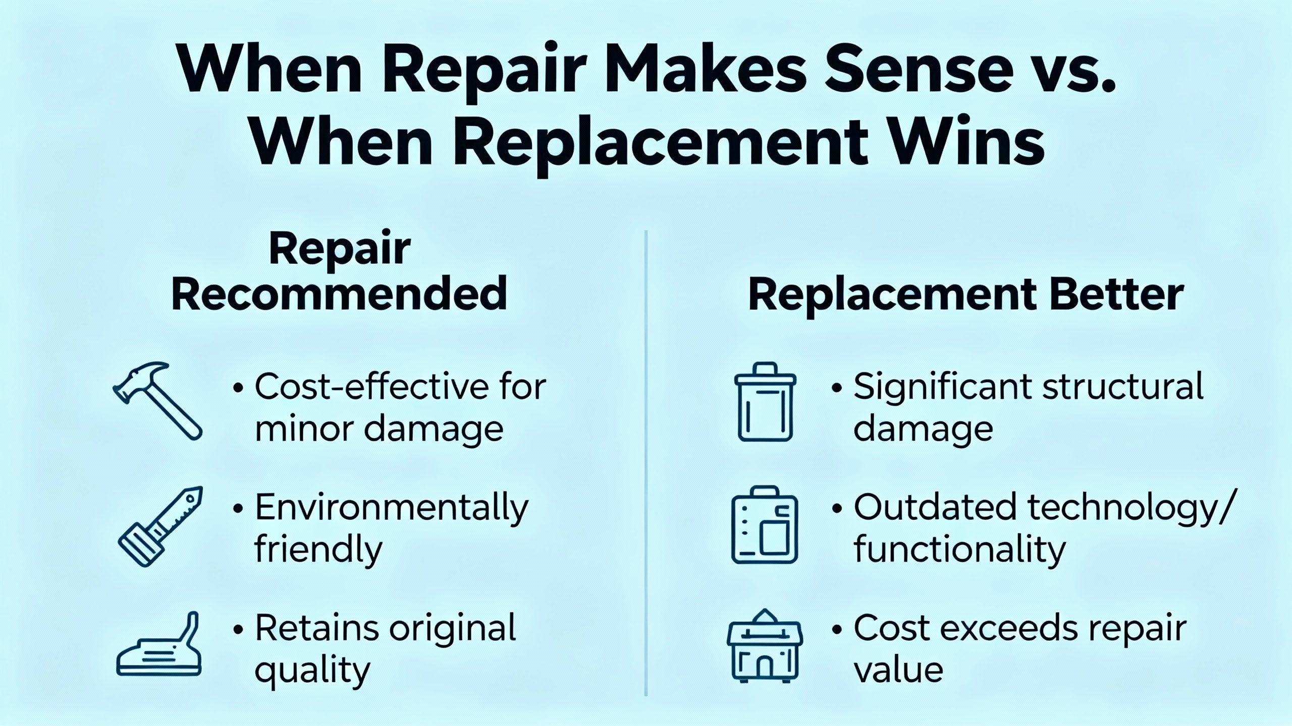
Repair services have their place, especially for outŌĆæofŌĆæwarranty units or when the plant cannot accept a model change without requalification. Global Electronic Services emphasizes that repair can be cheaper and faster than ripŌĆæandŌĆæreplace for many faults. That said, repeated power unit failures, recurrent microprocessor faults, and nonŌĆærecoverable errors are signals that replacement may be the shortest path back to production with lower risk of reoccurrence. Use your fault log and operating history to justify the decision: if faults correlate with ambient heat, power sags, or incorrect settings, a robust repair and a power hygiene program might be all you need. If the pattern points to silicon fatigue or repeated internal faults, stop throwing time at a deadŌĆæend.
Takeaway
PowerFlex drives advertise their state at the moment you need them most. If you capture that state and pair it with disciplined power, wiring, thermal, and parameter practices, you will cut downtime and avoid repeat trips. Most fixes are grounded in stable input power, clean and cooled electronics, realistic ramps and limits, sound cabling and shielding, and correct safety and network configurations. Maintain backups and keep firmware aligned. Plan your migrations against lifecycle dates and total cost, not sticker price alone, and preŌĆæstage everything you can. These systems repay methodical care with long stretches of uneventful production.
FAQ
Why do drives trip on overvoltage during deceleration and what actually fixes it?
Aggressive deceleration on a highŌĆæinertia load pushes energy back into the DC bus. That energy rapidly lifts bus voltage above limits and triggers F005 or a related bus event. The durable fix is slowing the stop by increasing deceleration time, enabling DC bus regulation if available, and adding a braking resistor sized for your duty profile. On applications with frequent stops, consider external shunt or capacitor modules and verify upstream surge protection if line events coincide with trips. These actions are widely documented by Industrial Automation Co. and repair providers.
How should I handle a Safety Open condition on a PowerFlex 525?
Treat it as a functional safety event. Confirm that Safe Torque Off channels and any safety relays are in the expected state, review wiring and jumpers if safety is not used, and check associated configuration settings. Safety inhibits are designed not to clear until the safety chain is healthy; forcing a reset bypasses the protection you rely on. Sources including UpFix and OxMaint emphasize verifying wiring and device states rather than trying to ŌĆ£reset throughŌĆØ a safety inhibit.
When should I use a braking resistor versus only tuning deceleration?
If lengthening deceleration to a safe, processŌĆæacceptable rate clears the bus events consistently, you may not need hardware. When process constraints require fast stops or when longŌĆæinertia loads regenerate in ways your bus regulator cannot absorb, a braking resistor is the correct tool. Sizing and thermal duty must match the stop profile. Guidance from Industrial Automation Co. and GESrepair aligns on this progression: tune ramps first, then add braking hardware as needed.
What should I do if a fault reappears immediately after a reset?
Stop the resets and isolate variables. Note the fault code and context, then uncouple the load where possible and test the motor unloaded. Verify supply quality, phase balance, and terminal torque; review motor data and protection setpoints; and inspect mechanical components for binding. If a communication or safety fault returns instantly, address those wiring and configuration paths first. OxMaintŌĆÖs reset guidance and general repair practices strongly discourage repeated resets without corrective action.
Can a UPS or isolation transformer help with nuisance power faults?
Yes, depending on the problem. Isolation transformers and UPS systems can attenuate sags, swells, and transients and present a cleaner source to the drive. UpFix notes that for bus voltage anomalies and regeneration, upstream stabilization can help. That said, many undervoltage and power loss trips resolve with simpler measures such as improved terminations, cable upsizing over long runs, input reactors, and better source coordination. Treat a UPS as part of a broader power quality plan, not a silver bullet.
What is the cleanest way to move parameters to a replacement drive?
PreŌĆæstage configurations using Connected Components Workbench and keep a knownŌĆægood baseline from the retiring drive. Where supported, export from the old unit using DriveTools SP and import into the new drive. HESCOŌĆÖs upgrade recommendations show that preloading parameters before the panel door opens cuts hours off swap and test and reduces the risk of configuration drift across your fleet.
Sources and Acknowledgments
This guide synthesizes driveŌĆæfamily specifics and practical remedies from Rockwell Automation user manuals and knowledge resources, Industrial Automation Co., HESCO, Global Electronic Services, UpFix, OxMaint, Precision Electronic Services, and Wireless Telemetry, combined with field experience commissioning, stabilizing, and upgrading PowerFlex installations in production environments.
References
- https://www.plctalk.net/forums/threads/the-frequent-loss-of-powerflex-4-and-40s-throughout-our-plant.107206/
- https://blog.hesconet.com/top-3-challenges-with-upgrading-powerflex-drives-and-how-to-overcome-them
- https://blog.upfix.com/allen-bradley-powerflex-527-fault-codes
- https://gesrepair.com/common-powerflex-vfd-issues-and-how-to-resolve-them/
- https://community.oxmaint.com/discussion-forum/how-to-reset-powerflex-525-drive-faults-common-issues-and-solutions
- https://www.pesquality.com/blog/allen-bradley-powerflex-753-fault-codes
- https://www.precision-elec.com/powerflex-755-troubleshooting-fault-codes/?srsltid=AfmBOooV6yljVeUxqoNX7BzAcxnWd56a0T_nZO27DE_-2qLxJjGePMj2
- https://wireless-telemetry.com/PDF/PowerFlex753_Fault_Codes.pdf
- https://industrialautomationco.com/blogs/news/allen-bradley-powerflex-525-fault-codes-complete-troubleshooting-guide?srsltid=AfmBOorO-GdGH-2wSAKnobKZE-fFzsS6WQVJuDnTloB8r2xdt6hwY30X
- https://www.dosupply.com/tech/2024/12/18/troubleshooting-made-easy-common-issues-and-solutions-with-powerflex-drives/?srsltid=AfmBOop9JbkBhHCNmAPHc6SeXLJXldI7GhUXLZ6phJeEgwSH6Du_KHGP


 Videos
 News
News Applications


Leave Your Comment