As a power system specialist focused on reliability, I see the fallout from unplanned trips ripple into UPS loading, inverter rideŌĆæthrough, and protection margins. On critical rotating assets that underpin power and process availability, Bently NevadaŌĆōstyle eddyŌĆæcurrent proximity transducer systems remain the gold standard for shaft vibration and position. This guide explains what ŌĆ£3300 XL compatibilityŌĆØ really means, how to select the right size family for your machinery, where thirdŌĆæparty ŌĆ£compatibleŌĆØ offerings fit, and how to avoid the hidden risks that undermine protection integrity and uptime. The emphasis is practical: clear definitions, selection criteria, crossŌĆæreference principles, and fieldŌĆætested advice, supported by reputable industry knowledge.
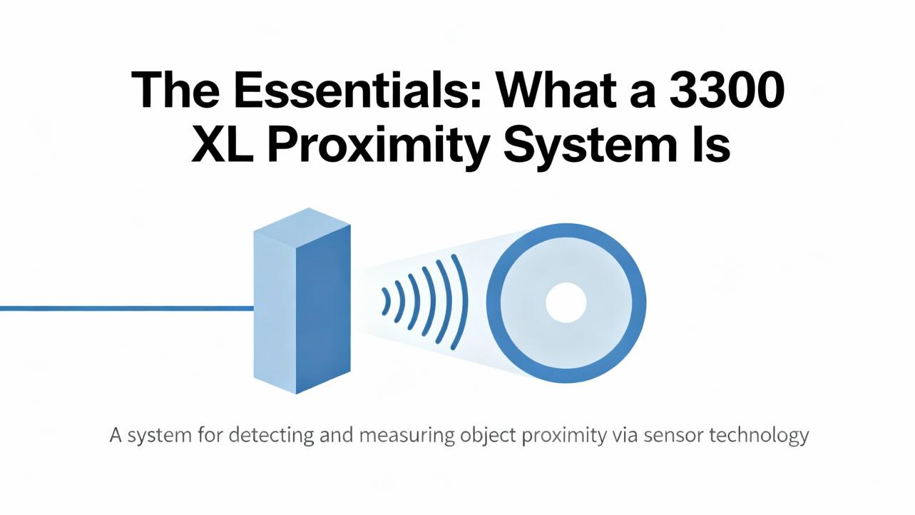
The Essentials: What a 3300 XL Proximity System Is
EddyŌĆæcurrent proximity systems convert the gap between a conductive shaft and a probe tip into a precise electrical signal. In the Bently Nevada architecture, each measurement channel is a matched trio consisting of the probe, the extension cable, and the Proximitor driver. The three parts operate as a system and are treated as one measurement chain. A key attribute of the 3300 XL families is factoryŌĆæcontrolled interchangeability within a family, which allows likeŌĆæforŌĆælike replacement of individual components without recalibration when you stay inside the exact family and size. The output is a scaled DC voltage for position with an AC component for vibration, widely used for condition monitoring and for protection tripping on highŌĆæcriticality machines.
When to pick displacement probes over accelerometers or velocity sensors depends on the fault frequency and the machineŌĆÖs bearing design. In broad terms, displacement sensors such as eddyŌĆæcurrent probes are preferred for lowŌĆæfrequency shaft motion and journal bearings, velocity for mediumŌĆæfrequency ranges, and accelerometers for higherŌĆæfrequency faults such as bearings, as outlined by CEMB USA and corroborated by vibration sensor selection primers from Fluke and CTC.
Electrical Characteristics You Must Respect
In the 3300 XL ecosystem the Proximitor driver is powered from a negative supply and produces a negative output that becomes more negative as the gap increases. Typical supply requirements sit around ŌłÆ24 VDC with an allowable range near ŌłÆ17.5 to ŌłÆ26 VDC, and a canonical displacement scale of ŌłÆ200 mV per mil, which is equivalent to approximately ŌłÆ7.87 V per millimeter. Terminals are commonly labeled Out, COM, and Vt where Vt is the negative supply input. This electrical polarity matters when you connect to plant systems. If you intend to feed a PLC or DCS analog input directly, ensure the input is truly differential and rated for bipolar ranges such as ┬▒10 V. If it is not, use a signal conditioner or a 4ŌĆō20 mA transmitter to avoid saturating inputs or creating ground faults. Practical wiring and interface challenges of the negative rail and negative output have been highlighted in community discussions and are a frequent source of commissioning snags.
Interchangeability vs ŌĆ£CompatibilityŌĆØ: DonŌĆÖt Build a Frankenstein System
Bently Nevada has documented, tested interchangeability within product families such as the 3300 XL 8 mm class. That means you can replace a damaged cable or a Proximitor with like components from the same family and expect the same gap and vibration response without recalibrating the entire measurement point. The discipline behind that outcome is a maintained metrology standard and statistically controlled manufacturing. The operational impact is simple: faster repair, fewer unique spares, and lower lifecycle complexity.
That interchangeability assurance does not carry across manufacturers. Baker Hughes has shared case histories where mixing an eddyŌĆæcurrent driver from one vendor with probes and cables from another produced nonŌĆælinear response, incorrect scale factors, and masked or exaggerated vibration. In one example, measurements attenuated above wide gaps, and in another, vibration appeared higher than it actually was. The risk is obvious: protection setpoints effectively change without a Management of Change review, so your shutdown limits are no longer what you think they are. The safe rule is to avoid mixedŌĆævendor sets. If you do not use Bently Nevada, then keep the probe, cable, and driver from the same thirdŌĆæparty vendor as a complete matched system. In short, compatibility in a catalog does not guarantee electrical interchangeability in protection service.
Size Families and How to Choose Them
The major 3300 XL families are defined by probe tip size, which correlates with linear range and mechanical envelope. The 5 mm class, about 0.20 in, fits tight installations and small rotors, the 8 mm class, about 0.31 in, is the most common generalŌĆæpurpose choice for critical pumps, turbines, and compressors, and the 11 mm class, about 0.43 in, suits large rotors with big shaft motion such as hydro units. When deciding among sizes, consider available space at the bearing, expected operating gap and vibration amplitude, and the linear measurement range required. Also ensure the installed extension cable length matches the driverŌĆÖs calibration for that family. Guidance from installation overviews such as MooreŌĆÖs selection notes consistently points to the 8 mm class as the default for most critical assets, the 5 mm when space forces it, and the 11 mm when displacements are large.
Target Material Calibration and Materials of Construction
EddyŌĆæcurrent systems measure changes in the probeŌĆÖs RF field caused by a conductive target. Because the coupling depends on the targetŌĆÖs electrical properties, the calibrated response is materialŌĆæsensitive. Proximitor systems are commonly factoryŌĆæcalibrated to AISI 4140 steel by default, and many suppliers offer calibration to alternate materials on request. If your shaft metallurgy differs, specify it up front; otherwise, your voltageŌĆætoŌĆædisplacement conversion will be off. From a mechanical standpoint, probes and cables are built for harsh environments. Typical constructions include a robust thermoplastic PPS tip carrier, a 304 stainless steel body for corrosion resistance, and 75ŌĆæohm FEPŌĆæinsulated coaxial cable in standard lengths such as roughly 1.6 ft, 3.3 ft, 16.4 ft, and 23.0 ft. Some accessories, like silicone tape over cable joints, are intended as moisture or dust barriers, but they are not a seal for hydrocarbon exposure. If the joint will see turbine oil, donŌĆÖt rely on silicone tape; specify proper connector boots and compatible materials. Where differential pressure exists between the probe tip and case, OŌĆærings such as Viton are used, but many probes are not pressureŌĆætested as shipped. If you need a pressure seal, order it that way and verify it.
What ŌĆ£CompatibleŌĆØ Means in Practice
Compatibility claims range from physically threading into the same tapped hole to full electrical interchangeability. For protectionŌĆægrade measurements, the only safe meanings are either component interchangeability within a 3300 XL family from Bently Nevada or complete matched sets from a single nonŌĆæBently vendor. Metrix, for example, offers a digital proximity ecosystem that is fieldŌĆæconfigurable and designed to work across multiple probe manufacturers, but the protectionŌĆægrade configuration is still a matched system that you treat as a single vendor set. CTC offers 4ŌĆō20 mA current drivers intended to translate the underlying dynamic voltage into a process current for PLCs and DCSs; these drivers include a convenient BNC for tapping the dynamic signal when you need deeper diagnostics, but the driver selection is part of a designed chain and should not be cobbled together with arbitrary probes.
The following compact matrix frames the decision space.
| Scenario | Safe Path | Compatibility Stance |
| Replace a damaged component in a 3300 XL 8 mm system | Use the same family probe/cable/driver component from Bently Nevada | Interchangeable within that family by design |
| Move from Bently Nevada to another brand for cost or standardization | Replace the entire channel as a matched probeŌĆæcableŌĆædriver set from the other vendor | Do not mix across manufacturers |
| Feed data to a PLC/DCS for trending, not trips | Use a 4ŌĆō20 mA proximity transmitter or a vendor driver designed for process inputs | Preserve a dynamic output tap for diagnostics when possible |
| Add coverage on lessŌĆæcritical assets without a protection rack | Consider lowŌĆæcost 4ŌĆō20 mA displacement transmitters or wireless accelerometers | Tie selection to fault modes and frequency content |

Selection Guide: Choosing the Right 3300 XL Family
If you want a reliable, defendable choice, align the family to the machineŌĆÖs physical scale and expected displacement. For compact machines where clearance is constrained, the 0.20 in family often solves mounting problems without sacrificing metrology. For most general industrial and power assets such as centrifugal pumps, generators, and compressors, the 0.31 in family remains the most deployed because its linear range covers typical gaps and machinery motion. For large rotors and machines with higher axial or radial excursions, the 0.43 in family provides the headroom to stay in the linear region. Across all families, match the extension cable length to the driverŌĆÖs calibration and confirm the target material calibration at purchase.
| Family (Tip Size) | Approx. Diameter (in) | Typical Use Case | Selection Emphasis |
| 5 mm | 0.20 | Tight envelopes, small rotors | Clearance limits, adequate linear range |
| 8 mm | 0.31 | General critical machinery | Balanced robustness, common spares |
| 11 mm | 0.43 | Large rotors, big motion | Extended linear range and setpoint headroom |
Interfacing to PLCs, DCS, and Protection Systems
Two common integration paths exist. For machinery protection and shutdowns, use a dedicated monitor from the measurement vendor that is designed to accept the proximity driverŌĆÖs dynamic signal and implement APIŌĆæstyle alarm and trip logic. Send 4ŌĆō20 mA trend values and relays from that monitor to the PLC or DCS. For condition monitoring without trips, use a 4ŌĆō20 mA driver that maps the AC peakŌĆætoŌĆæpeak vibration or the DC axial position into current, which is robust over long cable runs and easy to scale in controls. Drivers in this class often provide an isolated BNC on the front panel to let you connect a portable analyzer when deeper diagnostics are warranted. When direct voltage interfacing is unavoidable, ensure the analog input can accept negative voltages and that the ŌłÆ24 V driver supply is isolated so you do not inadvertently reference the COM to plant ground and short the supply. This negative rail detail is easy to miss and frequently causes noisy or clipped readings.
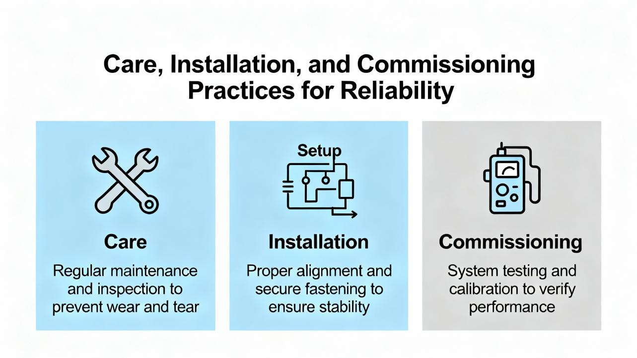
Care, Installation, and Commissioning Practices That Protect Reliability
Small discipline gaps during installation create big reliability holes later. Route coaxial cables away from highŌĆæcurrent power conductors and VFD leads to minimize induced noise. Confirm the extension length and family match before you pull cable; a wrong length changes the calibration. If you must use moisture barriers at joints, pick materials compatible with all contact fluids; do not rely on silicone tape near turbine oil. Torque mounting hardware to the vendorŌĆÖs specification and avoid bending loads on the probe that can slowly shift the gap. On startup, validate the scaling against expected values. A rule of thumb is that one mil of displacement corresponds to 200 mV change; if you observe material mismatch, verify the shaft metallurgy against the driver calibration. If you use current drivers for process trending, record the configuration scaling and hold a record of the associated dynamic output so you can line up current changes with waveform severity during troubleshooting.
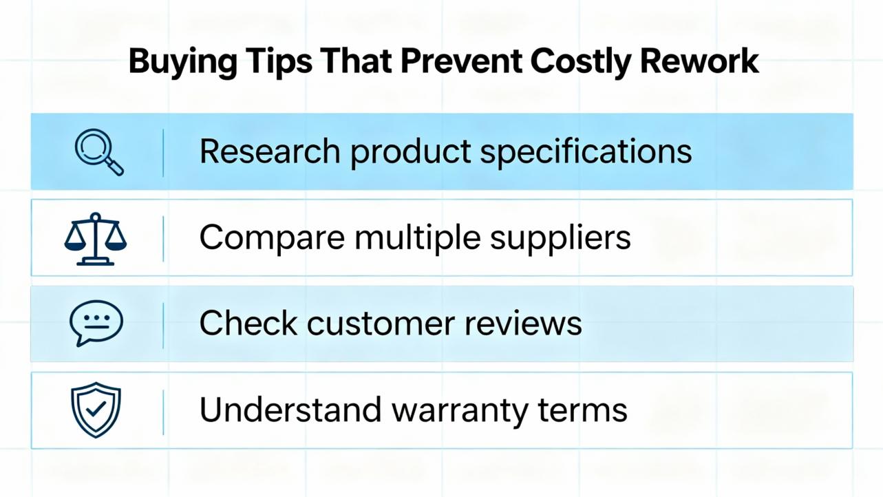
Buying Tips That Prevent Costly Rework
Define the machine family, the expected maximum displacement, and the installation envelope first; that narrows the size family and the linear range. Specify the target material. For each point, specify the extension cable length so the supply can be calibrated correctly. If your plant policy or an OEM standard forbids mixedŌĆævendor protection loops, document it on the purchase order; that alone prevents Frankenstein setups during urgent repairs. If process safety requires a pressure seal at the measurement point, order a pressureŌĆærated assembly and acceptance test it before install. For plants that prefer to trend in the PLC but keep protection in a vendor monitor, consider a proximity rack and companion 4ŌĆō20 mA outputs rather than rolling your own conversion around a negative supply and a bipolar voltage input. Maintain serialŌĆænumber traceability so you can replace at the component level within the family when field damage occurs.
Pros and Cons: Genuine 3300 XL vs ThirdŌĆæParty Matched Sets
A genuine 3300 XL family channel offers documented interchangeability, longŌĆæestablished metrology, and straightforward lifecycle spares. The tradeoff is typically higher acquisition cost and, at times, longer lead times. A thirdŌĆæparty matched set can reduce cost or align with a site standard while providing robust measurements and field configurability, such as the digital proximity platforms from established vendors. The risk is in assuming ŌĆ£compatibleŌĆØ means interchangeable; it does not. If you adopt a thirdŌĆæparty set, keep the chain intact and do not insert the components into a Bently Nevada loop. Some organizations require singleŌĆæmanufacturer protection loops for governance reasons; where that is the case, make the policy explicit and avoid exceptions. This governance note is based on field experience and is offered with moderate confidence because policies vary by site.
CrossŌĆæReference Strategy Without the Pitfalls
A sensible crossŌĆæreference is built around the function, not the thread size alone. First determine the measurement use case: radial vibration trend, axial position, or phase/speed. Then fix the size family based on the mechanical envelope and displacement headroom. Next choose the calibration for the shaft metallurgy. Finally, decide whether you will remain in the 3300 XL family or move to a thirdŌĆæparty matched set. If you stay with 3300 XL, component crossŌĆæreference is straightforward inside the same family. If you move to a different vendor, select the complete set and keep it intact through installation, spares, and maintenance procedures. For controls integration, decide early between dynamic voltage into a protection monitor versus a 4ŌĆō20 mA transmitter into a PLC. That decision affects every downstream spec from cable runs to cabinet terminations.
Frequently Asked Questions
What does ŌĆ£ŌłÆ200 mV per milŌĆØ mean, and how does it relate to the gap? It is the displacement scale factor. For every 0.001 in change in shaftŌĆætoŌĆæprobe gap, the output changes by about 0.200 V, becoming more negative as the gap increases. The same scaling is approximately ŌłÆ7.87 V per millimeter. This rule holds when the system is calibrated to the correct target material and extension length.
Can I mix a thirdŌĆæparty probe with a 3300 XL Proximitor if the threads fit? No, not for protection service. Mixed systems can be nonŌĆælinear or misŌĆæscaled even if the gap voltage looks reasonable at install. To avoid false trips or missed trips, keep probe, cable, and driver from one manufacturer as a matched set, or stick with all 3300 XL components within the same family.
How do I power a Proximitor that needs ŌłÆ24 VDC when my plant supply is +24 VDC? Use an isolated supply or DC/DC converter so that the Proximitor sees its negative rail referenced to its own COM. Do not bond the COM to plant 0 V unless the design explicitly allows it. Many PLC analog inputs cannot accept negative voltages, so plan a signal conditioner or a 4ŌĆō20 mA transmitter when needed.
Should I pick 0.20 in, 0.31 in, or 0.43 in probes? Choose based on space and expected motion. Use the 0.20 in family for tight spaces on smaller rotors, the 0.31 in family for general critical assets, and the 0.43 in family when large axial or radial displacement demands a longer linear range. Always match cable length and confirm target material calibration.
Can I send proximity measurements straight to my PLC? You can if the inputs are truly bipolar and properly isolated, but most sites prefer a 4ŌĆō20 mA proximity transmitter for trending or a dedicated protection monitor for alarms and trips, with 4ŌĆō20 mA and relays wired to the PLC. That approach reduces wiring pitfalls and preserves diagnostic access to the dynamic signal.
Takeaway
For protectionŌĆægrade measurements on critical rotating machinery, ŌĆ£3300 XL compatibilityŌĆØ does not mean you can mix and match across vendors. Interchangeability exists within Bently Nevada families because it is engineered and verified; outside that boundary, treat any ŌĆ£compatibleŌĆØ product as a complete matched set from its manufacturer and keep it intact. Choose probe size by space and displacement headroom, specify target material calibration, and match the extension length to the driver. Decide early whether you are feeding a protection monitor or a PLC and select drivers and interfaces accordingly. These disciplined choices prevent silent scale errors, reduce nuisance trips, and preserve the reliability margins that keep UPSs, inverters, and power protection equipment operating inside design limits.
References
Bently Nevada (Baker Hughes) ORBIT article on proximity probe system interchangeability; Moore Automation overview on selecting the right 3300 XL proximity system; CEMB USA primer on vibration transducers; CTC technical notes on PRO Line proximity hardware and 4ŌĆō20 mA drivers; Metrix Vibration product information on proximity probes and digital proximity systems; Fluke guidance on vibration sensors; industry forum discussions on powering and interfacing Bently Nevada proximity sensors.
- https://web.mit.edu/6.101/www/reference/ABCprobes_s.pdf
- https://www.afpm.org/data-reports/technical-papers/qa-search/question-47-what-are-best-practices-corrosion-probe
- https://www.rikasensor.com/a-how-to-choose-the-best-ph-probe-for-water-quality-monitoring.html
- https://www.worldofcontrols.com/bently-nevada-proximity-probes-supplier
- https://cemb-usa.com/types-of-vibration-transducers-and-their-purpose/
- https://www.mooreplc.com/blog/selecting-the-right-bently-nevada-3300-xl-proximity-system-for-your-machinery_b221
- https://www.powergearx.com/bently-nevada-probe-health-a-guide-for-industrial-automation/
- https://www.pruftechnik.com/many-types-of-vibration-sensors/
- https://www.realpars.com/blog/vibration-sensor
- https://reesscientific.com/blog/temperature-probe-what-to-know


 Videos
 News
News Applications


Leave Your Comment