Allen-Bradley PowerFlex drives sit at the heart of many plantsŌĆÖ critical motors. When they fault, you do not just lose a drive; you lose production, quality, and often the trust of operations. From my work supporting PowerFlex fleets in everything from water plants to material handling lines, I have learned that successful troubleshooting is rarely about staring at one fault code in isolation. It is about testing the entire drive system in a disciplined way: power, motor, load, parameters, wiring, and network.
This guide brings together field-proven practices and guidance from Rockwell Automation documentation, industrial service providers such as Global Electronic Services, Industrial Automation Co, HESCO, and specialized repair shops and integrators. The goal is a practical system testing approach for Allen-Bradley PowerFlex drives, with a focus on diagnostics and proving reliability rather than just clearing the next fault.
Why PowerFlex Fault Diagnosis Demands a System View
PowerFlex variable frequency drives are sold as energy savers and life extenders for motors, and that claim is generally true. Articles from Global Electronic Services and Roc Industrial describe how PowerFlex drives improve efficiency, reduce mechanical stress, and extend equipment lifespan. The flip side is that when a drive trips, the event is usually a symptom of stress somewhere else: poor power quality, contamination, bound loads, miswired safety circuits, or misconfigured parameters.
At the same time, lifecycle pressures are increasing. Rockwell has announced that PowerFlex 4, 40, and 40P will reach official end-of-life in June 2025. HESCO and other Rockwell distributors are already helping plants plan upgrades to PowerFlex 523 and 525 platforms. Those upgrades are not plug-and-play; panel footprints, wiring, communication protocols, and safety architectures change. How you diagnose and test the system now shapes how smoothly you can migrate later.
A good testing strategy treats each fault as a data point in a wider pattern. Industrial Automation Co emphasizes logging fault codes, load conditions, temperature, and process state to reveal recurring issues like afternoon undervoltage or startup overcurrent. Academic work on fault detection and diagnosis for electrical drives echoes the same idea: detect, identify, diagnose, and recover in a repeatable loop rather than reactively resetting and hoping.
How PowerFlex Drives Communicate Faults
Faults, warnings, inhibits, and non-resettable conditions
An Allen-Bradley drive ŌĆ£faultŌĆØ is any condition that prevents the drive from running. Global Electronic Services explains that fault codes are the primary diagnostic tool for identifying the underlying malfunction. On modern platforms like PowerFlex 527, Rockwell documentation and repair guides describe several categories of codes:
- FLT codes for actual faults that stop motion
- INHIBIT codes when the drive is disabled by Safe Torque Off or enable logic
- INIT codes for initialization, firmware, or configuration problems
- NODE alarms and faults for network and communication issues
Some fault conditions are auto-resettable after a time delay; others are non-resettable and indicate deeper issues such as wiring errors, corrupted parameters, or hardware damage. The distinction matters. Auto-reset and run strategies, covered in Global Electronic Services material, can be safe for minor, well-understood faults. Non-resettable faults are a strong signal that you should stop trying to restart and move into structured testing or professional repair.
Using the HIM and fault queues
For most PowerFlex drives, the Human Interface Module is the quickest way to view diagnostic history. Global Electronic Services describes a common workflow:
You use the HIM ŌĆ£Choose ModeŌĆØ menu, open ŌĆ£Control Status,ŌĆØ and then view the fault and warning queues. A fault remains displayed until you issue a Clear Faults command or a Drive Reset. Clear Faults removes soft and warning faults; Drive Reset clears all faults. If a fault, such as one on a PowerFlex 4, will not clear even after a full reset, that is a red flag that the drive or the connected system requires repair rather than repeated attempts to run.
On platforms like PowerFlex 755T, RockwellŌĆÖs troubleshooting notes add further nuance. A flashing red status indicator points to a serious fault, often requiring you to press Stop, cycle power, and use the HIM diagnostic menu to clear faults after corrections. A flashing yellow indicator tied to messages such as ŌĆ£DigIn Cnfg BŌĆØ or ŌĆ£DigIn Cnfg CŌĆØ indicates configuration conflicts in digital inputs rather than a pure hardware problem.
In short, the HIM is not just a reset button. It is a diagnostic instrument and should be treated as such in every test plan.
A Structured Test Strategy for PowerFlex Drives
Fault detection and diagnosis literature for industrial drives, including fuzzy logic approaches, describes four conceptual phases: detect that a fault happened, identify the most relevant variables, diagnose type and location, and then recover. In practice on PowerFlex systems, that maps to a simple but powerful testing structure.
Stabilize and verify incoming power
Many drive faults are driven, literally, by the power system feeding them. Under Voltage faults such as F004 on PowerFlex 525 drives occur when input voltage drops below the drive minimum. Over Voltage faults like F005 occur when the DC bus voltage exceeds its safe limit during regeneration or line spikes. Industrial Automation Co and Global Electronic Services both stress that when a drive will not start or trips on voltage-related faults, the first checks are not inside the drive.
You verify upstream breakers and fuses and confirm that incoming three-phase voltage is correct and balanced. You inspect input wiring for loose terminations, which are common causes of undervoltage and intermittent trips. For long cable runs or undersized conductors, voltage drop can be enough to trigger F004 even if the source looks good at the panel; in those cases Industrial Automation Co recommends heavier-gauge conductors or a line reactor, and slower ramp-up (via P039 on a PowerFlex 525) to ease inrush.
Bus-related codes on more advanced drives, such as S23, S25, S29, S34, S35, and S37 on a PowerFlex 527, point to issues like single-phase loss, bus thermal overload, or power loss in the DC link. UpFixŌĆÖs guidance here is clear: verify that all three phases are present, inspect precharge circuits, monitor for source droop or glitches, and consider adding an isolation transformer or UPS support where the AC source is unstable. Only after that do you consider parameter tweaks such as adjusting deceleration profiles or adding bus capacitors or shunt modules.
Check thermal and mechanical health
Thermal overload faults are among the most common in the field. On PowerFlex 527, UpFix points to faults like FLT M10, S07, S08, S11, S13, and S29 indicating thermal overload of the control module, inverter, motor, or bus regulator, often around 110 percent modeled thermal capacity. PowerFlex 525 drives report heatsink overtemperature as F029. PowerFlex 700 and general PowerFlex guidance from Global Electronic Services and DO Supply links overheating to bound loads, clogged cooling paths, and ambient temperature.
A practical test sequence around thermal issues includes several basic, but often neglected, actions. You visually inspect the enclosure and drive vents for dust and debris; clogged filters and vents drastically reduce airflow. You verify cooling fan operation, listening for bearing noise and looking for seized blades. You confirm that ambient temperature around the drive is within spec; where it is consistently high, you improve ventilation, add forced-air cooling, or implement air conditioning for panels, as GES recommends.
Mechanical load is the other side of the thermal coin. Bound or excessive mechanical load manifests as faults such as Drive OverLoad, Excessive Load, HW or SW OverCurrent, OverSpeed Limit, and Motor Overload. DO Supply and Global Electronic Services both emphasize disconnecting or uncoupling the load during autotune or testing when speed cannot be reached, checking for seized pumps, clogged impellers, worn fans or pulleys, and gradually reapplying load with extended acceleration to avoid shock.
Table 1 summarizes how common fault families line up with likely causes and initial tests.
| Fault family | Example codes (from sources) | Typical root causes | HighŌĆævalue tests and actions |
| Undervoltage | F004, S35 | Supply dips, loose terminals, long runs | Measure line voltage, tighten wiring, upsize cables, adjust rampŌĆæup |
| Overvoltage / regen | F005, S34 | Fast decel, high inertia, spikes | Lengthen decel, add braking resistor, enable DC bus regulator (P041) |
| Thermal overload | F029, FLT M10, S07, S08, S11, S13, S29 | High ambient, clogged vents, overload | Clean vents, verify fans, reduce load, improve ventilation |
| Overcurrent / ground | F013, S10, S16 | Cable faults, insulation breakdown | Megger test, inspect insulation, confirm wire gauge and routing |
| Motion / overspeed | FLT S03, S04, S50ŌĆōS57, S61 | Bad profiles, tuning, limits | Verify motion profile, retune loops, check limits and enable wiring |
The exact codes and naming vary by platform, but the test philosophy is consistent.
Validate wiring, cabling, and grounding
If there is one root cause that shows up in nearly every drive troubleshooting article, it is poor wiring. For PowerFlex 700, Global Electronic Services lists loose or partially disconnected wiring as one of the most common causes of erratic behavior, speed instability, and overcurrent. Such issues trigger faults like Analog In Loss, DPI Port Loss, Port 1ŌĆō6 DPI Loss, and Load Loss. The same pattern appears in PowerFlex 525 material from Industrial Automation Co, where Port 5 adapter faults (F122) result from bad Ethernet cables or connections.
Cable integrity is just as important as terminations. DO Supply describes PowerFlex drive cables as high-power, multi-conductor assemblies with insulation, jacketing, and shielding; contamination or fraying can cause communication errors and drive trips. The recommendation is straightforward: inspect insulation and terminations regularly and do not hesitate to replace damaged or contaminated cables. Roc Industrial echoes this, citing erratic behavior and encoder faults resolved by replacing worn feedback and power cables.
Grounding and shielding practices matter as well, especially for drives on noisy shop floors. Industrial Automation Co recommends shielded, VFD-rated motor cable with the shield grounded at one end, typically the drive side, and physical separation between motor and control wiring. That combination reduces electrical interference, ground faults, and false digital inputs. When ground faults like F013 on PowerFlex 525 or S16 on PowerFlex 527 appear, megger testing of motor insulation, inspection of conduits for abrasion, and verification of shield terminations are core tests.
Digital input wiring deserves its own attention. Rockwell troubleshooting for PowerFlex 755T notes that incorrect input wiring can leave the terminal block without control. For two-wire control, a correctly wired Run, Run Forward, Run Reverse, or Jog input is required. For three-wire control, both Start and Stop inputs must be present and correctly wired; configuring a Start input without a Stop input is an error. The documentation also stresses that the 24 Volt Common must be tied properly to the Digital Input Common. When these conditions are not met, the drive can show flashing yellow indicators with messages such as ŌĆ£DigIn Cnfg BŌĆØ or ŌĆ£DigIn Cnfg CŌĆØ and alarms in status parameters.
A disciplined wiring test phase therefore includes visual inspection, tightening where appropriate, verification of commons and shields, and confirmation that digital input wiring matches the intended control mode.
Confirm parameters, safety functions, and control logic
Fault codes are not only about hardware conditions; they are also about how the drive has been programmed.
For PowerFlex 700, Global Electronic Services describes a range of faults tied to incorrect or corrupted parameters, such as Analog In Loss, Params Defaulted, Parameter Chksum, Replaced MCBŌĆæPB, and IXo VoltageRange. These issues are often associated with memory leaks or voltage transients. The recommended remediation is to clear faults, power cycle, restore factory defaults where necessary, then reprogram parameters and back them up using the HIM or tools like DriveExplorer or DriveExecutive.
Parameter management on PowerFlex 525 is equally important. Industrial Automation Co calls out several key parameters that directly influence fault behavior. P041 controls the DC Bus Regulator and is a primary tool for managing regenerative energy and suppressing overvoltage trips without overreliance on hardware. P042 sets the current limit, allowing you to minimize nuisance trips from short overloads while still protecting hardware. P050 allows fault masking for non-critical transitional faults, and P090 governs auto reset attempts, enabling limited automatic restarts after minor events. The guidance here is to use these parameters carefully and only after verifying that underlying electrical and mechanical issues have been resolved.
Safety inputs and logic layers must also be attacked methodically. UpFix documentation on PowerFlex 527 emphasizes that safety and inhibit conditions such as INHIBIT M05, S01, S02, and S05 indicate that Safe Torque Off or axis enable circuits have disabled the power structure or that the motor is not configured. Recommended steps include verifying safety input wiring and device states, checking Ethernet components in safety networks, confirming axis enable levels, and ensuring correct motor configuration in Studio 5000.
For PowerFlex 525, safety design goes deeper. A Certified Machinery Safety Expert in a PLCTalk discussion explains that Safe Torque Off alone on a PowerFlex 525 can achieve up to Category 3 / PLd for certain stop categories when properly integrated. The drive provides a ŌĆ£Safe StateŌĆØ status bit, exposed in parameter b006, that can serve as a monitored safe-state signal in reset logic when used with a safety controller over EtherNet/IP. However, the same expert stresses that safety functions must be designed and modified only by appropriately trained engineers, and that to reach higher performance levels like Category 3 / PLe, you need external safety actuators such as monitored contactors in addition to the driveŌĆÖs STO.
From a diagnostic standpoint, this means that when safety-related inhibits occur, you do not bypass them. You verify wiring, logic conditions, safe-state bits, and control sequences against the original safety specification.
Test communications and networks
As plants upgrade from DSI-based legacy drives to Ethernet/IP-connected PowerFlex platforms, network issues have become a leading cause of mysterious drive behavior. HESCO points out that older PowerFlex families often relied on serial interfaces, while modern PowerFlex 523 and 525 drives have built-in Ethernet/IP. Plants that are not Ethernet-ready may need concurrent network upgrades, which introduces configuration errors, IP conflicts, and infrastructure weaknesses.
Industrial Automation CoŌĆÖs coverage of F122, the Port 5 Adapter Fault on PowerFlex 525, traces most of these events to bad cables, IP address conflicts, disconnected host PCs, or firmware mismatches. The practical test sequence is familiar to anyone who has worked with industrial Ethernet. You reseat or replace the Ethernet cable, power cycle the drive, and verify firmware and device description files. You then re-scan the drive in Connected Components Workbench or Studio 5000 with the correct Add-On Profile versions.
A clear example of network testing steps comes from One MotionŌĆÖs PowerFlex 525 setup guide. To configure a static IP address, parameter C128 must be set to enable static addressing. IP octets are then entered through parameters C129 to C132, and subnet mask octets via C133 to C136. After a power cycle, you verify that these parameters retained the expected values. Only then do you test connectivity from a computer configured in the same subnet, for example by pinging the driveŌĆÖs address and confirming that replies are received. If parameters do not hold or the drive does not respond, you repeat configuration and involve IT or AllenŌĆæBradley support as required.
On integrated motion platforms such as PowerFlex 527, UpFix notes that NODE alarms and NODE faults can be caused by late or lost controller updates, clock jitter and skew, duplicate IP addresses, or power-board communication issues. Recommended mitigation includes simplifying network topology, removing unnecessary devices, using shielded cables and high-performance switches, separating signal and power wiring, and sometimes updating firmware. These are system-level tests, not just drive-level tweaks.
The theme across all of these examples is that communication testing is both electrical and logical. You must verify cabling, address configuration, firmware compatibility, and controller configuration together.
Run functional tests under controlled load
Once electrical supply, thermal environment, wiring, parameters, safety, and networks have been verified, you are finally ready for functional tests under load. This is where motion performance and feedback issues often reveal themselves.
UpFix describes a family of motion-performance and limit faults on PowerFlex 527, such as S50, S51, S54, S55, S56, S57, and S61, which flag overtravel, excessive position or velocity error, overtorque or undertorque, or enable-input problems. Recommended actions include verifying limit switch wiring and enable inputs, checking axis configuration and motion profiles, tuning position and velocity loops, and confirming that the drive and motor are properly sized. Adjusting tolerances and torque limits is explicitly suggested only after true root causes are addressed.
Feedback faults like S41 and S43 are a different category. They indicate noisy, missing, or illegal encoder feedback. UpFix advises inspecting feedback cables and connectors, verifying shielding and grounding, reducing mechanical shock or vibration, checking encoder DIP switches, and if necessary cycling power or replacing the motor or encoder. These actions should be part of a structured motion-testing procedure, starting at low speed and load before ramping up.
Throughout functional testing, the fault codes themselves remain your guide. When new codes appear, you loop back through the earlier phases: identify the variables implicated, run targeted tests, and only then consider parameter changes. This is essentially the fuzzy logic fault diagnosis cycle applied in practice: symptoms are observed, mapped to potential causes with expert rules, and then narrowed down by targeted tests.
Preventive Maintenance and Testing for Long-Term Reliability
The most efficient PowerFlex fault is the one that never occurs. Every major repair and troubleshooting provider in the research emphasizes preventive maintenance and continuous testing as the real reliability lever.
Global Electronic Services connects contamination directly to thermal faults on PowerFlex 700. Contaminants such as dust, moisture, oil, and metal particles restrict airflow, raise temperatures, and cause faults like control board overtemperature and heatsink overtemperature. Their recommended control measures are straightforward: disconnect power, inspect heatsinks, fans, and vents, remove debris with compressed air, and maintain a cleaning schedule. Where pollutants are unavoidable, they suggest isolating the drive from the source or using an enclosure, and sending heavily contaminated units for professional service.
Corrosion receives similar treatment. GES and DO Supply describe corrosion as a combination of oxygen, moisture, and heat attacking metal surfaces and boards, showing up as overheating or bus overvoltage faults such as I1 to I3 Bus Overvolt or I1 to I3 power-layer interface overtemperature. To control it, they recommend verifying ambient temperature and fan performance, using dehumidifiers or sealed housings to limit condensation, and in some cases operating continuously to avoid moisture cycling. If overvoltage faults persist after environmental corrections, replacing the power-layer interface board may be required.
Industrial Automation Co suggests panel hygiene roughly every three to six months: cleaning, confirming clear airflow, checking fans, and inspecting for loose or corroded connections. They also advocate systematic logging of faults and operating conditions, which supports trend-based maintenance rather than reactive repairs.
Parameter backup and configuration management is another preventive practice. Both Industrial Automation Co and Global Electronic Services highlight the importance of saving parameter sets via Connected Components Workbench or the HIM. When drives fail or parameters become corrupted, having a validated backup allows you to commission a replacement in minutes rather than hours, and makes planned upgrades faster and less risky.
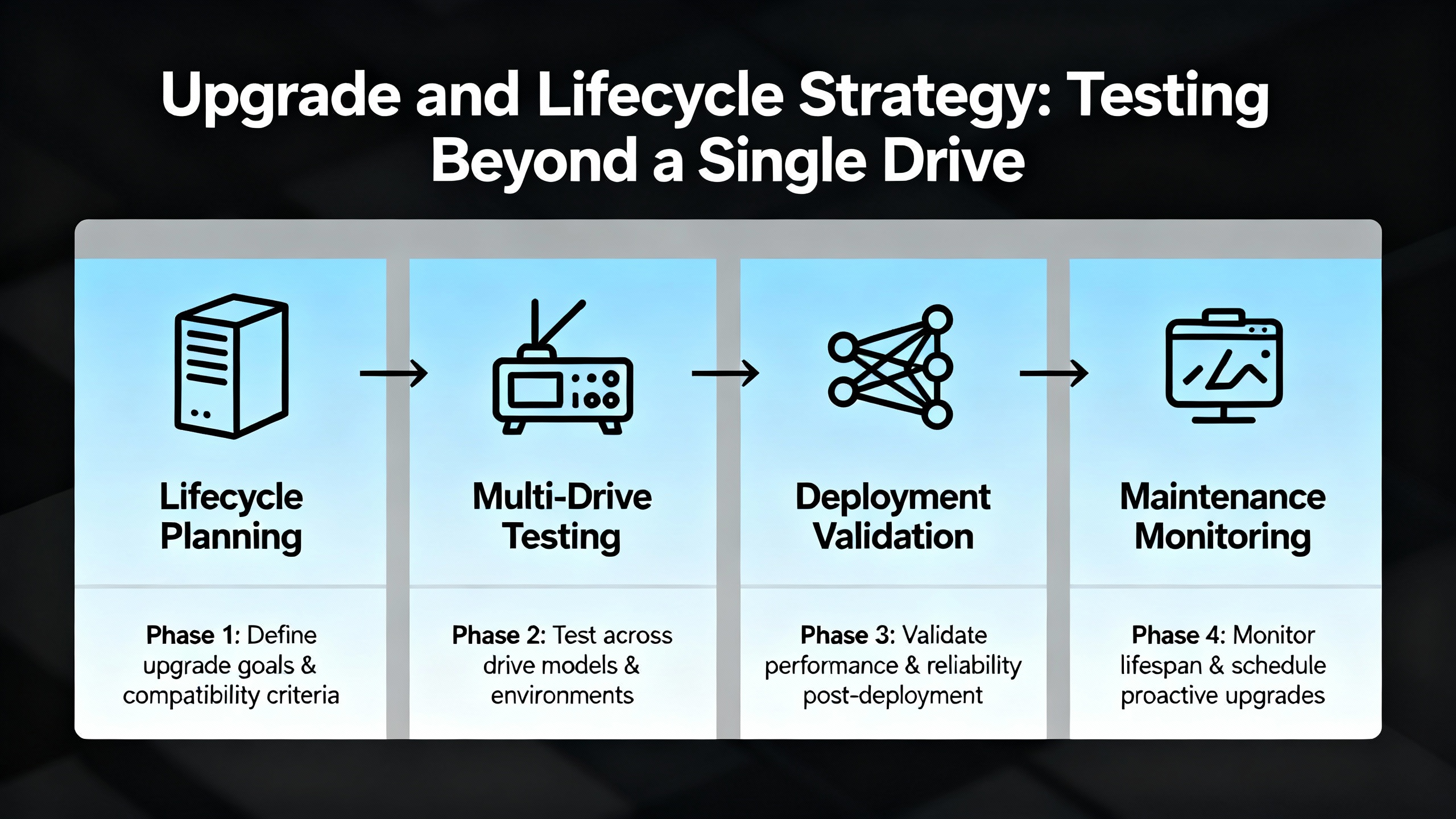
Upgrade and Lifecycle Strategy: Testing Beyond a Single Drive
With PowerFlex 4, 40, and 40P going end-of-life in June 2025, many plants are facing large-scale drive migrations. HESCO describes three main upgrade challenges: physical differences between legacy and modern PowerFlex drives, communication changes, and downtime risk.
Physical differences include footprint, mounting, and terminal locations. These may force panel rework and rewiring, which in turn demand verification and testing of every power and control circuit involved. Communication changes are equally significant. Older PowerFlex drives commonly used DSI serial interfaces, whereas modern PowerFlex 523 and 525 drives favor Ethernet/IP. Facilities without Ethernet-ready infrastructure must plan network upgrades, which bring their own commissioning and testing requirements.
HESCO recommends an Installed Base Evaluation as a first step. This is a systematic inventory of existing drives, including lifecycle status, that allows mapping each legacy unit to a modern replacement. From a testing perspective, it provides a baseline: which circuits, communications, and safety paths will be touched, and therefore what must be verified.
To control downtime, HESCO emphasizes pre-staging and pre-programming replacement drives. Using tools like Connected Components Workbench and DriveTools, you build parameter sets and transfer configurations from old to new drives before installation. Once on site, you can focus on wiring verification, network checks, and functional run-up tests rather than parameter entry from scratch. They also point out that some distributors can provide temporary loaner drives to keep lines running if unexpected issues arise during testing.
Drive selection itself has reliability and testing implications. HESCO cautions against selecting the cheapest one-for-one replacement, such as a PowerFlex 4M, because some lower-tier models are already near their own end-of-life. This can force another round of rework and testing in only a few years. PowerFlex 525 is often recommended instead as a more modern, long-lived platform with Safe Torque Off and built-in Ethernet/IP to support diagnostics and future predictive maintenance. Financial planning should focus on total cost of ownership, including engineering hours, panel modifications, networking, training, and the cost of repeated outages.
In my experience, treating a drive upgrade as a testing project rather than a pure hardware swap yields better outcomes. You plan tests around each affected function: power, motor rotation, safety chains, communication with PLCs, and integration with higher-level systems such as historians or maintenance logs.
Putting It All Together: A Practical Testing Mindset
When an Allen-Bradley PowerFlex drive faults, it can be tempting to see it as a nuisance and rush to clear it. The research and field experience tell a different story. A fault code is the driveŌĆÖs way of saying something in the system has crossed a boundary: thermal, electrical, mechanical, or logical. PowerFlex 525, 527, 700, and 755 families all convey rich diagnostic data if you are willing to read it carefully and test systematically.
A robust testing mindset starts with safe, simple checks: verifying power quality, cleaning and cooling, confirming wiring and grounding, and checking that parameters and safety circuits match the design intent. It then moves into deeper diagnostics: megger tests for ground faults, encoder and feedback checks, network verification with ping and configuration tools, and controlled functional tests under load. Preventive maintenance, parameter backups, and upgrade planning extend this mindset over the lifecycle of your drive fleet.
For critical industrial operations, that approach turns PowerFlex fault diagnosis from a series of emergencies into a structured reliability program. You reduce downtime, protect your motors and drives, and create a technical foundation that will make your eventual migrations to newer PowerFlex platforms smoother, safer, and easier to justify.
If you align testing with this system view, each fault code becomes less of a surprise and more of a useful measurement in keeping your power system stable, your drives healthy, and your production running.

References
- https://www.academia.edu/65411029/Fault_Detection_and_Diagnosis_in_Industrial_Systems_Based_on_Fuzzy_Logic_a_Short_Review
- https://ebiltegia.mondragon.edu/xmlui/bitstream/handle/20.500.11984/5319/Data-Driven%20Fault%20Diagnosis%20for%20Electric%20Drives%20A%20Review.pdf?sequence=1&isAllowed=y
- https://www.plctalk.net/forums/threads/allen-bradley-powerflex-4-failures.67658/
- https://blog.hesconet.com/top-3-challenges-with-upgrading-powerflex-drives-and-how-to-overcome-them
- https://resources.onemotion.tech/setup-troubleshooting-powerflex.html
- https://blog.upfix.com/allen-bradley-powerflex-527-fault-codes
- https://gesrepair.com/common-powerflex-vfd-issues-and-how-to-resolve-them/
- https://www.precision-elec.com/powerflex-755-troubleshooting-fault-codes/?srsltid=AfmBOoozNb93fBd3waZVHNZxfhBrnnhl8PzJs7vfW_KUsc-rKEIDSYYq
- https://www.rocindustrial.com/repair-page/powerflex-feedback-cable-troubleshooting-troubleshooting-guide
- https://industrialautomationco.com/blogs/news/powerflex-525-fault-codes-what-they-mean-and-how-to-fix-them-2?srsltid=AfmBOor-5DxgsPHORwVE9BUcQ4oMEsh7doAzrjTmtm_kLwnOYkCUL_F9


 Videos
 News
News Applications


Leave Your Comment