When an AllenŌĆæBradley PLC drops out in a plant that depends on UPS systems, inverters, and sensitive power electronics, you are not just losing automation; you are putting protection and continuity at risk. A tripped controller can leave an unmonitored UPS, an inverter running blind, or a transfer scheme that will not operate when the lights flicker. From a power reliability standpoint, a ŌĆ£PLC not workingŌĆØ event is a risk to both equipment and revenue.
As a reliability advisor, I see the same pattern repeatedly: teams jump straight into the logic looking for a ŌĆ£software bug,ŌĆØ while the real root cause is upstream in power quality, network configuration, or hardware health. The good news is that AllenŌĆæBradley platforms are rich in diagnostics, and with a structured approach you can usually restore control quickly and prevent a repeat failure.
This guide walks through practical, field-tested steps for CompactLogix, ControlLogix, MicroLogix, and Micro800ŌĆæclass controllers, with a special focus on power supply and protection environments. The guidance aligns with recommendations from Rockwell Automation documentation, Global Electronic Services, HESCO, Industrial Automation Co., ElectricNeutron, and other technical sources.
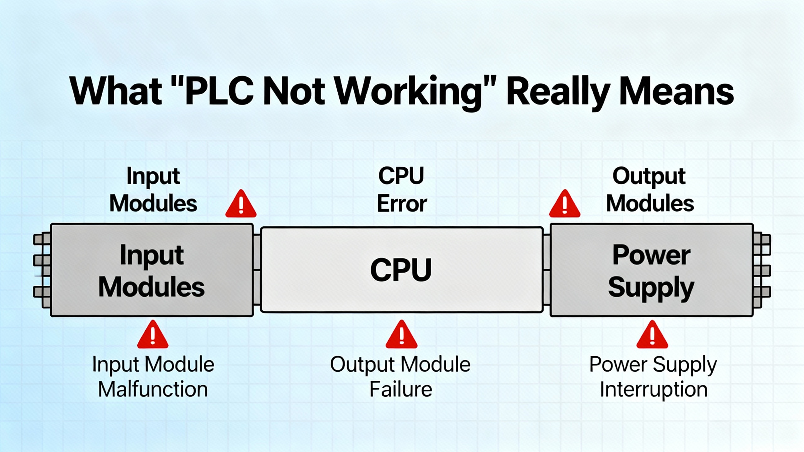
What ŌĆ£PLC Not WorkingŌĆØ Really Means
ŌĆ£PLC not workingŌĆØ can describe several very different situations. Clarifying which one you are seeing is the first diagnostic decision.
Sometimes the PLC is physically dead: no LEDs, no network presence, no reaction to a keyswitch. This usually points to power, grounding, or catastrophic hardware failure. In other cases, the controller has power but is not executing logic. The keyswitch may be in Program mode, the controller may be holding a major fault, or firmware and software versions might be mismatched. A third category is when the PLC runs normally but cannot talk to the outside world. In that case you may have loss of communication with I/O, an HMI, SCADA, or a UPS or inverter interface, even though the CPU itself is healthy.
AllenŌĆæBradley PLCs are modular by design. A typical system has a processor or CPU module that executes the program, a backplane that distributes power and data, I/O cards that interface with sensors, contactors, and inverters, and a power supply module feeding the chassis. In MicroLogix or Micro850ŌĆæclass controllers these functions are often integrated into a single housing. Understanding this structure helps you target tests: controller failure does not always mean controller replacement.
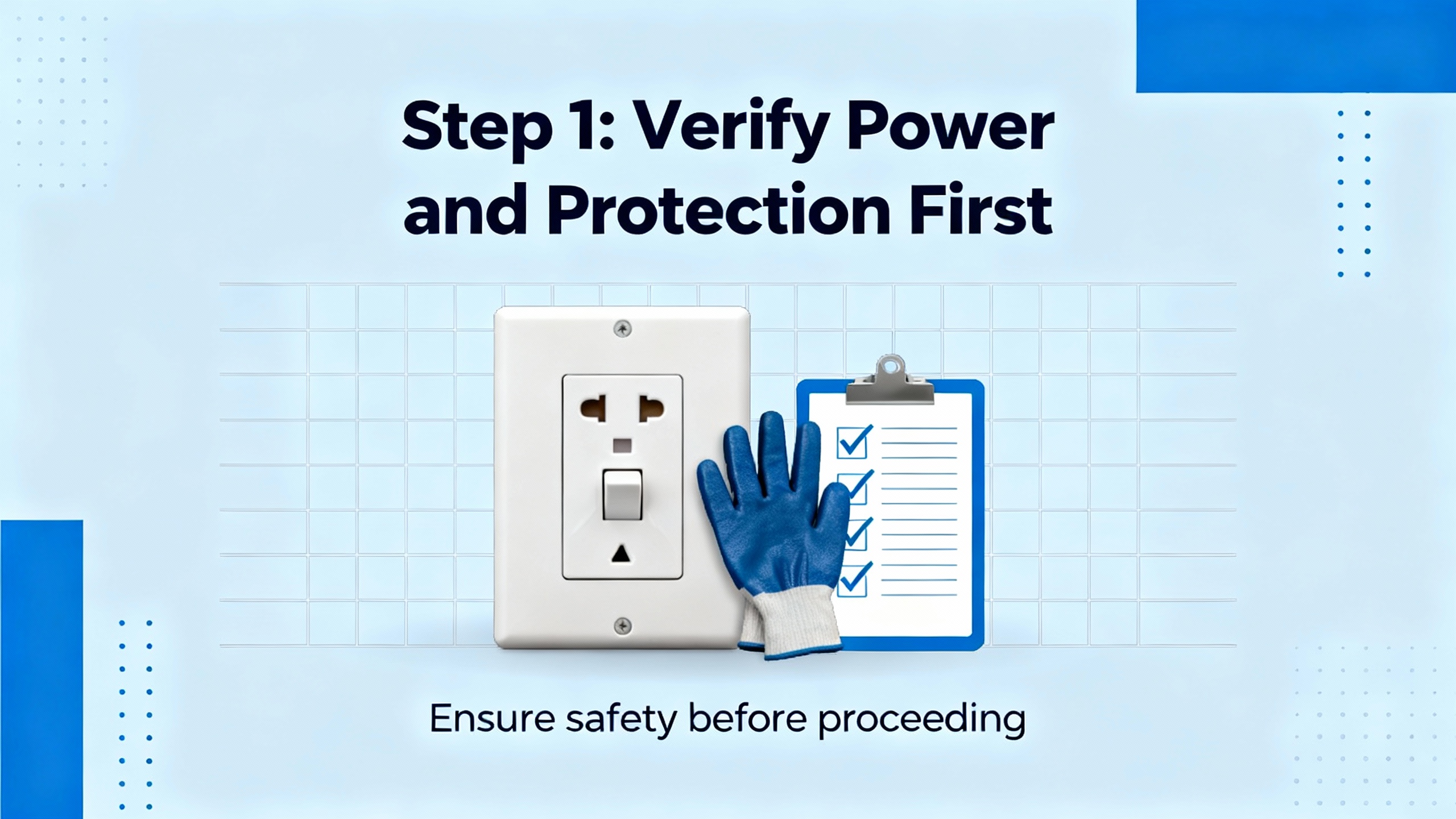
Step 1: Verify Power and Protection First
Across industrial sites, electrical problems are the single biggest driver of PLC outages. Global Electronic Services reports that power issues account for as much as 80 percent of ControlLogix failures, and that aligns closely with what I see in powerŌĆæintensive facilities. Before you dive into software, prove that the controller has clean, stable power and that your UPS or inverter infrastructure is actually protecting it.
Confirm PLC Power Supply Health
For Logix systems, the control bus typically expects a regulated 24 V DC supply, and Global Electronic Services highlights a healthy range of about 20.4 to 27.6 V DC at the terminals. Use a calibrated multimeter to measure at the PLC power input, not only at the panel feed. If you see readings below the lower threshold, or large swings when loads start and stop, you have found a prime suspect.
Look closely at the power supply and terminals. Loose or corroded terminations create intermittent dropouts that can reboot a PLC or corrupt memory. Tightening screws and cleaning oxidation is a simple, highŌĆævalue action. Check surge protection devices; if surge arresters or transient suppressors have taken a hit and degraded, the PLC is sitting exposed to future spikes. Ground faults in the control circuit can cause erratic behavior and must be located systematically using insulation and continuity tests, as described by Global Electronic Services and PDFSupply troubleshooting guides.
If you suspect the power supply module itself, swapping in a knownŌĆægood spare is often faster than trying to test it in circuit. HESCO and Industrial Automation Co. both note that power supply faults can manifest as widespread, seemingly random module failures and communication problems; replacing a weak supply can make a ŌĆ£hauntedŌĆØ system behave normally again.
Look Upstream at UPS, Inverters, and Grounding
In many commercial and industrial sites, the 24 V DC supply feeding the PLC ultimately comes from a UPS, a DC bus on an inverter, or a control power transformer behind power protection equipment. A surprising number of control failures trace to these upstream sources.
First, verify that the UPS or inverter is correctly sized and configured for the control load, and that its output voltage is stable under both normal and transfer conditions. Brownouts on the UPS output during transfer, or sag when the inverter starts large loads, can pull PLC power below the acceptable band even if the equipment does not fully shut down. Power quality meters or data logs from the UPS can reveal dips and swells that match PLC reboot times.
Second, review grounding and bonding around the PLC and power electronics. PDFSupply and Asteam Techno both stress that electrical noise and poor grounding cause random resets and corrupted memory. Shielded cables should be grounded at the correct end, control grounds should be solid, and highŌĆæfrequency noise sources such as variable frequency drives or welding machines should be physically and electrically separated from lowŌĆævoltage control wiring.
Environmental Stress: Heat, Dust, and Vibration
If the PLC is mounted in a power room with UPS systems, transformers, and inverters, the thermal and mechanical environment may be harsh. Global Electronic Services explains how heat, dust, and vibration gradually degrade performance: clogged cabinet filters reduce cooling; poor seals allow conductive dust into modules; loose mounting allows boards to flex and connectors to loosen.
Check cabinet intake filters and replace or clean them as needed. Confirm that enclosure doors close properly and gaskets are intact. Use builtŌĆæin cabinet temperature sensors if present or add inexpensive sensors to monitor internal temperatures, especially during hot summer days or near fully loaded UPS and inverter stacks. Fans must operate freely with clear airflow paths. Rockwell Automation and HESCO both recommend routine visual inspection; a quick look at filters, fan operation, and module seating during monthly maintenance goes a long way toward preventing temperatureŌĆæinduced controller failures.
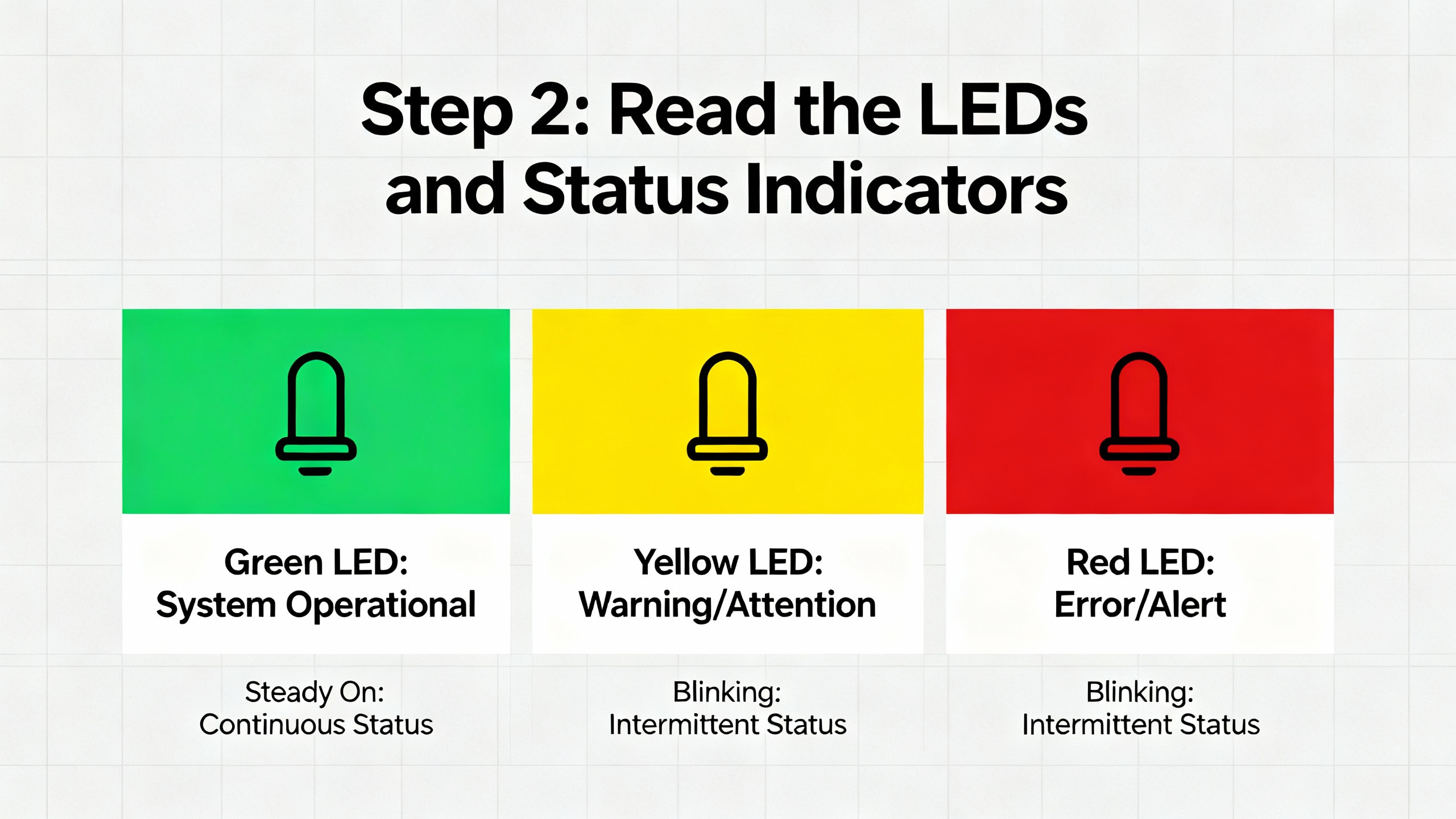
Step 2: Read the LEDs and Status Indicators
AllenŌĆæBradley PLCs and I/O modules are chatty if you know how to listen. Status LEDs condense a lot of diagnostic information into patterns of solid and flashing colors. Industrial Automation Co., ElectricNeutron, and PLCDepartment consistently emphasize starting with these indicators before changing any code.
You will typically see a processor status LED, I/O status LED, and communications indicators on the CPU and network modules. A solid green CPU LED usually indicates a healthy controller in Run mode; a solid red LED often means a major fault has stopped execution. ModuleŌĆælevel red or flashing LEDs point to I/O faults, firmware mismatches, or backplane communication issues.
The table below summarizes common indicator patterns and what they usually mean in practice.
| Indicator behavior | Likely problem area | Typical first check or action |
| CPU LED solid red | Controller major fault; logic or hardware failure | Connect with Studio 5000 or RSLogix, read fault code, and review last program changes before clearing the fault |
| I/O status LED not ŌĆ£OKŌĆØ or off | I/O module or chassis communication failure | Inspect module seating and backplane power, compare I/O configuration in the project to installed modules |
| Module LED flashing red | Recoverable module fault or field wiring issue | Check wiring for short or overload, review module diagnostics, and consider swapping with a spare |
| Network LED off or blinking abnormally | Loss of communication with network or HMI | Verify Ethernet cables, switches, IP settings, and driver configuration as described by RealPars and Industrial Automation Co. |
Treat LEDs as a roadmap, not as decoration. Before pulling cards or rewriting logic, note every abnormal indicator and photograph the rack. That snapshot often becomes invaluable if a cleared fault later needs deeper analysis.
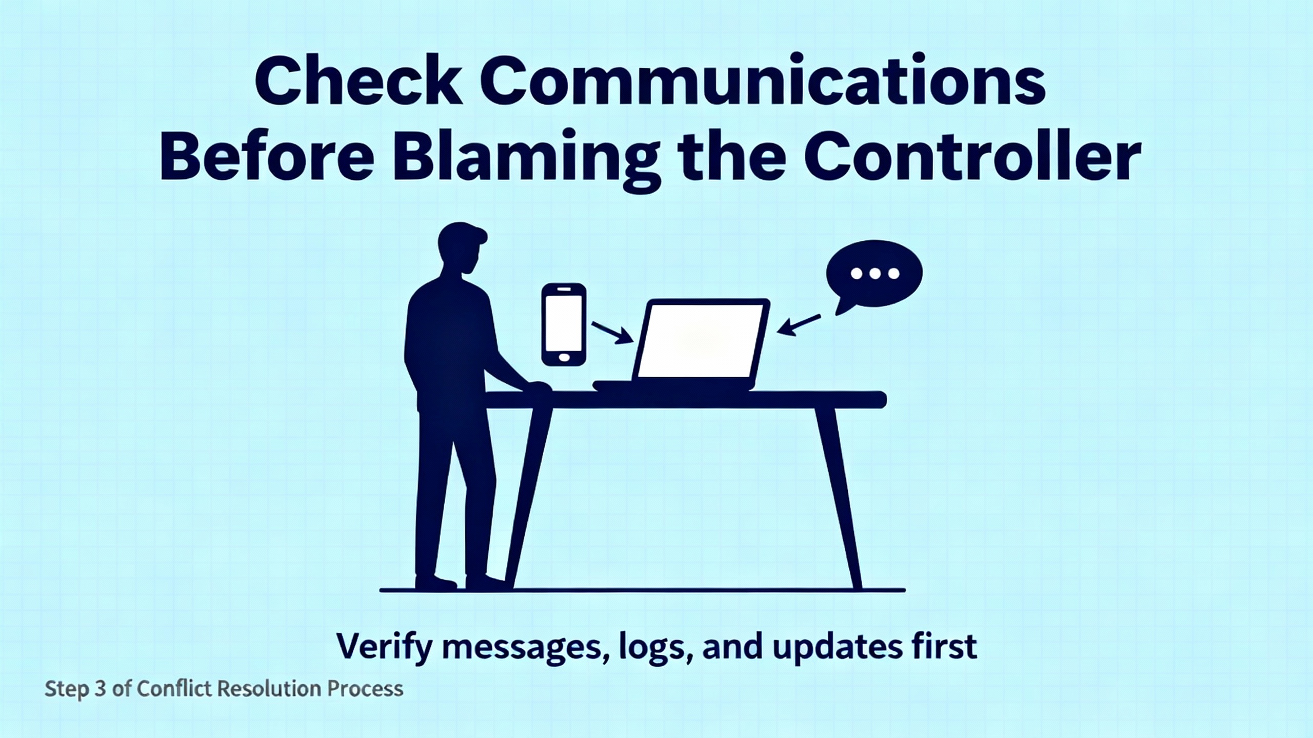
Step 3: Check Communications Before Blaming the Controller
Many ŌĆ£PLC not workingŌĆØ calls turn out to be ŌĆ£engineering laptop not talkingŌĆØ or ŌĆ£HMI not respondingŌĆØ rather than a failed controller. HESCO, ElectricNeutron, PLCDepartment, Industrial Automation Co., and RealPars all stress that communication faults are among the most common and most confusing issues.
Confirm You Can See the PLC from Your Engineering Station
For Logix controllers, engineers typically use RSLinx Classic or FactoryTalk Linx as the communication layer under Studio 5000. RealPars shows a very practical pattern: engineers open FactoryTalk LinxŌĆÖs Who Active window, expand the EtherNet/IP driver, and see nothing. The PLC appears ŌĆ£deadŌĆØ when in reality the driver is not browsing.
Within FactoryTalk Linx, open the driver settings and make sure continuous discovery, often labeled as ŌĆ£Make Discovery Continuous (Auto browse),ŌĆØ is enabled. When Auto browse is running, the driver icon animates and the tool periodically sends discovery messages on the network. Note that browsing continues only when the driver itself is selected; if you click on a device under that driver, discovery pauses and the list freezes.
Next, confirm that your PC is actually in the same IP subnet as the PLC network. EtherNet/IP discovery is limited to one subnet, so mismatched IP address or mask on the laptop will make the controller invisible even if it is healthy. RealPars recommends checking the PCŌĆÖs network interface configuration and ensuring FactoryTalk Linx is bound to the correct physical adapter when multiple network cards or WiŌĆæFi are present.
Validate Network Configuration and Cables
If the driver is browsing but the PLC or remote I/O nodes are still missing, focus on physical and logical network health. Global Electronic Services and ElectricNeutron highlight improperly terminated networks, damaged Ethernet cables, and IP address conflicts as frequent culprits.
Verify Ethernet patch cords and switch ports by substitution with knownŌĆægood components. Inspect connectors for bent pins or loose locking tabs. At the configuration level, review IP addresses, subnet masks, and gateway settings for both PLC and HMI or SCADA nodes. Industrial Automation Co. and PLCDepartment both point to duplicate IP addresses and incorrect subnet masks as chronic causes of lost communication and ŌĆ£I/O not respondingŌĆØ errors.
Within RSLinx or FactoryTalk Linx, clear stale entries. RealPars notes that a red ŌĆ£XŌĆØ icon usually marks a device that used to be present but is offline now, often due to a cable disconnection or address change. Removing offline devices allows you to see the current network state more clearly. Yellow question mark icons often represent devices the driver can see but does not fully understand, usually thirdŌĆæparty equipment lacking a recognized EDS file. In that case, upload the EDS from the device if supported, or install the file provided by the vendor so the driver can communicate correctly.
Distinguish PLC Failure from HMI or SCADA Failure
Once you can ping the controller and see it in the driver, you have effectively proven that the PLC hardware and basic network path are intact. If the HMI or SCADA still shows ŌĆ£PLC not responding,ŌĆØ compare their configuration to what you see in RSLinx or FactoryTalk Linx. Lost communication may be as simple as an incorrect shortcut name, wrong path, or a misspelled controller tag.
Industrial Automation Co. underscores that many ŌĆ£no communication with HMI or SCADAŌĆØ incidents are configuration problems rather than hardware failures. Validating IP, gateway, driver selection, and project paths takes minutes and can prevent needless module replacements.
Step 4: Diagnose Controller Faults in Studio 5000 or RSLogix
When the PLC has power and the network can see it, but the CPU is stopped or the process is not running, the next step is to interrogate the controller with programming software. ElectricNeutronŌĆÖs troubleshooting guide lays out a structured workflow that I recommend as standard practice.
Connect using Studio 5000 Logix Designer for CompactLogix and ControlLogix platforms or RSLogix 500 for SLC and MicroLogix systems. Check the controller mode; if it is in Program rather than Run or Remote Run, logic will not execute. Sometimes this is intentional after maintenance, but often it is a sign that a fault forced the processor out of Run mode.
Within controller properties, review the fault tabs. Industrial Automation Co. describes controller major faults as critical CPU stops, often caused by logic errors or hardware issues. Typical logicŌĆærelated faults include watchdog timeouts when the scan exceeds its allowed execution time, array index outŌĆæofŌĆæbounds errors, and divideŌĆæbyŌĆæzero operations. ElectricNeutron highlights how a poorly configured periodic task once overlapped with a continuous task in a petrochemical plant, causing recurring ControlLogix CPU major faults and emergency shutdowns until the task period was extended and verified.
For each fault, read and record the specific fault code and description. Rockwell AutomationŌĆÖs Knowledgebase and manuals explain the meaning and recommended actions. In many cases the immediate action is to correct the offending logic, clear the fault, and return the controller to Run. Avoid repeatedly clearing the fault without understanding the root cause; PLCtalk community guidance on fault handling, as summarized in research notes, strongly cautions against automatic restarts after major faults without at least one deliberate operator or supervisor acknowledgment and a safeŌĆæstate check.
If the controller is stuck in Program mode even after faults are cleared, check startup mode settings in controller properties and review safety interlock logic. ElectricNeutron notes that startup programs sometimes deliberately hold the controller out of Run until specific safety or process conditions are met.
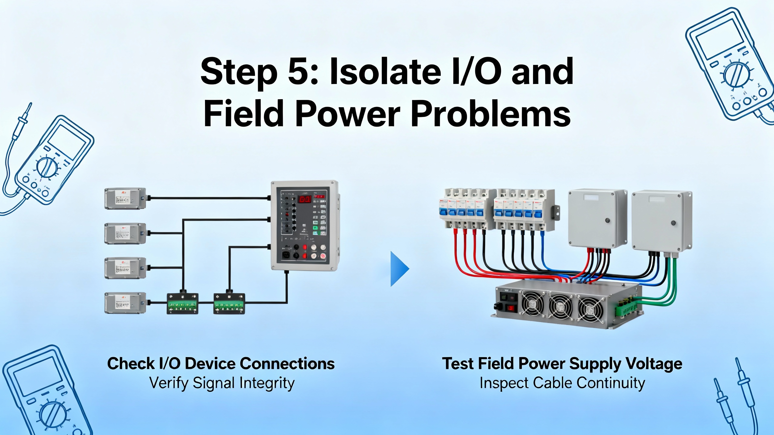
Step 5: Isolate I/O and Field Power Problems
Once you know the CPU is running correctly, attention turns to whether the PLC can actually see and control the outside world. Industrial Automation Co. identifies ŌĆ£I/O Not RespondingŌĆØ errors as one of the most common problems across AllenŌĆæBradley platforms. PLCDepartment and HESCO echo that many failures manifest as unresponsive sensors, dead motor outputs, or analog values frozen at default.
One key distinction is between backplane power and field power. The I/O module may be powered and communicating with the controller while the field devices it feeds are not energized. Verify that external supply voltages for field circuits, such as 24 V DC for sensors or control relays and higher voltages for contactors and valves, are present and within specification. Tripped breakers, blown fuses, or failed small power supplies often explain ŌĆ£deadŌĆØ downstream equipment even when the PLC thinks it is energizing outputs.
To determine whether an I/O module itself is faulty, use a mix of diagnostics and substitution. Studio 5000 and RSLogix provide moduleŌĆælevel status and connection diagnostics. If a particular slot consistently reports errors while adjacent modules are healthy, reseat the suspect card and inspect the backplane connector for damage. HESCO and ElectricNeutron both recommend temporarily swapping the module with a knownŌĆægood spare of the same type; if the fault follows the module to the new slot, the hardware is likely bad. If the fault stays in the original slot, look for configuration mismatch, backplane issues, or wiring problems.
On the input side, PLCDepartment points out that faulty or miscalibrated sensors and wiring mistakes are more common than failed CPUs. Check input states in the software while operating the field devices and compare them to expected behavior. For outputs, monitor actuator status and feedback in the PLC, verify wiring continuity, and check for overloads or short circuits that could trip protective devices or damage output channels.
Step 6: Rule Out Memory, Firmware, and Program Issues
When power, communications, and I/O all appear sound, but the controller behaves unpredictably, memory and firmware health move to the top of the list. Global Electronic Services stresses that memory problems often surface as erratic programs or frozen outputs, and they recommend a disciplined sequence of checks.
Battery and Nonvolatile Memory Health
Older SLC 500 and MicroLogix controllers, as well as some CompactLogix and ControlLogix models, rely on a battery to retain memory during power loss. Industrial Automation Co. and HESCO both highlight ŌĆ£Battery Low or MissingŌĆØ alarms as a major risk, since losing batteryŌĆæbacked memory can wipe out user programs or realŌĆætime clock data during an outage.
Measure battery voltage if accessible; Global Electronic Services suggests replacing batteries showing less than about 3.0 V. In practice, the safer approach is timeŌĆæbased replacement. HESCO recommends proactively changing PLC batteries every two to three years during planned downtime rather than waiting for lowŌĆæbattery alarms. Always maintain a verified external program backup before battery replacement, especially in older systems.
Program Corruption and Checksums
Memory corruption can result from voltage fluctuations, interrupted downloads, or failing memory modules. Global Electronic Services advises downloading and comparing program checksums to detect corruption. If the program on the PLC does not match your master copy, treat the situation carefully.
Clear unused memory segments where appropriate and run builtŌĆæin diagnostics for faulty memory cards or modules. When you suspect a corrupted program, restore a knownŌĆægood backup and verify operation rather than attempting incremental patching on a possibly damaged base. PDFSupply emphasizes disciplined programming and documentation practices, including version control and thorough testing, to reduce the risk of introducing corrupt or inconsistent code.
Firmware and Software Version Alignment
Industrial Automation Co. and Asteam Techno both point out that mismatched firmware and programming software versions are a frequent cause of strange behavior and communication errors, including Studio 5000 being unable to go online with a controller. Confirm that the projectŌĆÖs revision matches the controllerŌĆÖs firmware version. Rockwell tools such as ControlFLASH or ControlFLASH Plus are designed to upgrade controller firmware to a specific version before downloading an equally versioned project.
On the software side, keep Studio 5000, RSLogix, and Connected Components Workbench at versions compatible with your installed controllers. When working with Micro800 or MicroLogix controllers, Asteam Techno recommends aligning firmware using ControlFLASH and, if necessary, downgrading project versions to match older controllers.
Where controllers report lowŌĆæmemory faults, HESCO suggests removing unused routines or tags, reducing unnecessary historical and trending data, and, if capacity remains tight, upgrading to a controller with more memory. That decision is particularly important in UPS and inverter systems with increasingly dataŌĆærich monitoring and analytics requirements.
PowerŌĆæQuality Related PLC Failures: Patterns from the Field
The research and vendor guidance align strongly with practical field experience in powerŌĆæsensitive facilities. In UPS rooms, inverter halls, and main switchgear suites, the majority of PLC disturbances I encounter link back to power quality and grounding.
Voltage sags on the control power bus, caused by simultaneous starts of fans, pumps, or batteryŌĆæroom HVAC equipment, can dip below the tolerance band, triggering controller resets or causing subtle memory issues long before the main process power shows any visible problem. Repeated small dips are especially dangerous; they may never trip protection devices yet still stress power supplies and capacitors.
Electrical noise from highŌĆæfrequency inverters and variable frequency drives can couple into PLC wiring, particularly when shield terminations, segregation, and grounding are not carefully executed. Asteam Techno describes how electrical noise interference from nearby highŌĆævoltage or highŌĆæfrequency equipment leads to random faults and unpredictable logic in Micro850 controllers; the same physics apply to Logix platforms. Proper routing, shielding, and the use of ferrite cores or filters on sensitive lines become part of the control system design, not an afterthought.
For powerŌĆæcentric systems, the PLC is effectively the ŌĆ£brainŌĆØ supervising UPS modules, static transfer switches, and inverter control. When that brain fails due to powerŌĆæquality issues, the system may stay in a lastŌĆæknown state without the ability to adapt to a disturbance. Investing in clean control power, appropriate UPS or DCŌĆæDC converters for the control layer, and wellŌĆædesigned grounding often delivers more reliability improvement than any single PLC hardware upgrade.
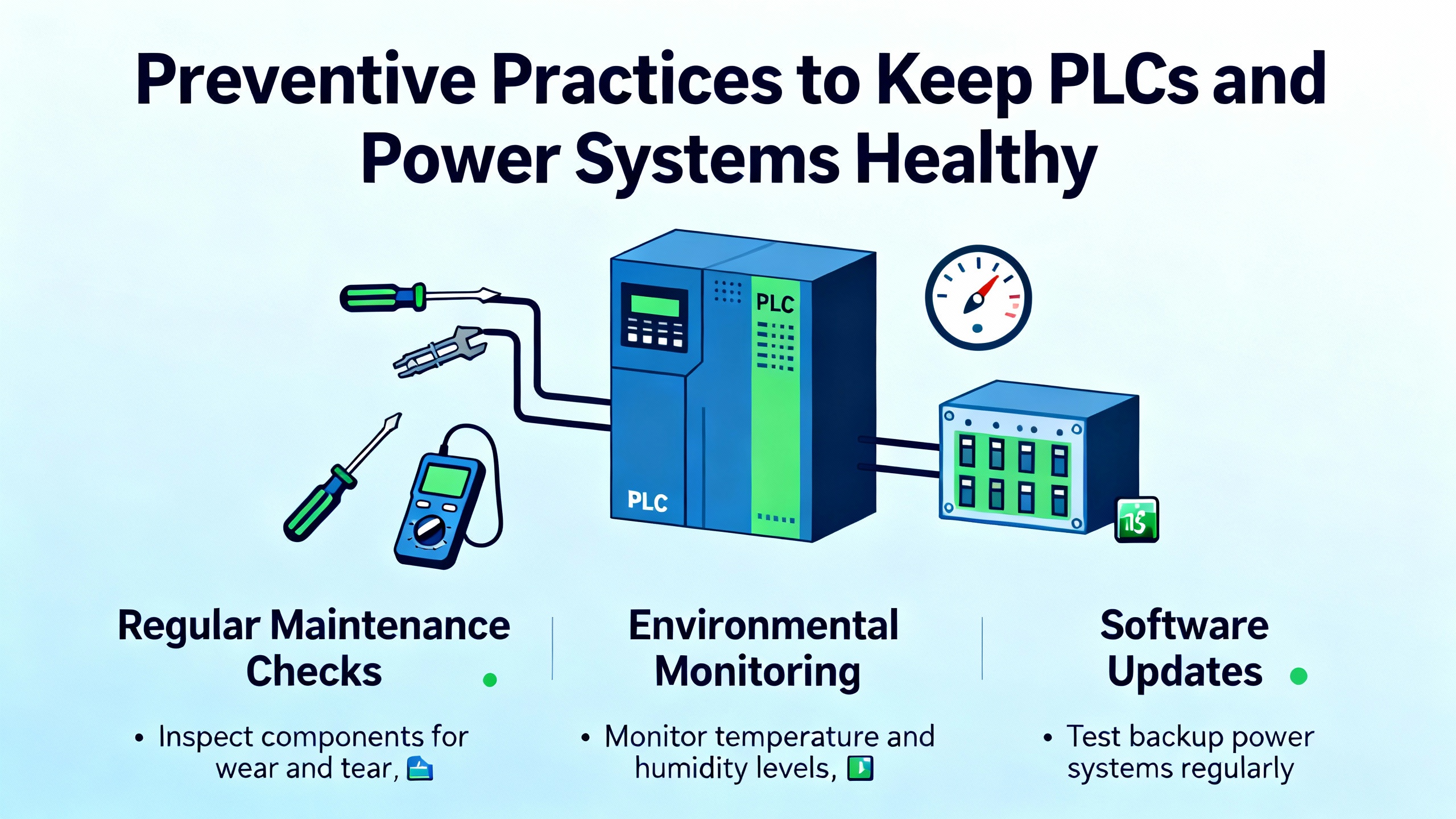
Preventive Practices to Keep PLCs and Power Systems Healthy
Several sources converge on the idea that structured preventive maintenance is the most effective way to avoid surprise controller failures.
HESCO recommends monthly visual inspections of wiring, modules, and cabinet interiors, supported by proactive battery replacements every two to three years, cabinet temperature monitoring, and regular program backups at least quarterly or after any significant logic change. Global Electronic Services encourages regular monitoring of power quality and internal cabinet temperatures, as well as quarterly network performance tests and thermographic scans to uncover hot spots and overloaded components.
ElectricNeutron and IDSPower stress disciplined software practices: document all logic changes, use version control, and ensure technicians are trained in Studio 5000, controller architectures, and standard PLC languages such as ladder logic and structured text. Routine simulation or offŌĆæline testing using tools like RSLogix Emulate, where available, reduces the chance of deploying faulty code into live power systems.
PLCDepartment and PDFSupply emphasize that preventive work should extend beyond the PLC rack. Regularly clean dust from enclosures, tighten or replace damaged wiring, verify sensor calibration, and check actuator health. In power supply rooms, pay particular attention to controlŌĆæpower transformers, DC supplies feeding PLCs and protection relays, and the integrity of UPS outputs dedicated to control systems.
For organizations with many controllers, RockwellŌĆÖs AssetCentre can automate backups and track changes across fleets of PLCs, while TechConnect contracts provide access to Rockwell engineers and knowledge resources that can shorten complex troubleshooting. In smaller facilities, even a simple shared folder with dated backups and change logs provides a baseline level of configuration control that dramatically speeds recovery after a failure.
When to Call in a Specialist
Not every PLC failure requires outside help, but there are clear triggers where bringing in a specialist reduces risk and downtime. HESCO suggests that inŌĆæhouse teams are generally well suited to tasks such as I/O card replacement, battery swaps, restoring knownŌĆægood programs, reseating modules, and resolving straightforward communication issues.
On the other hand, multiŌĆæsystem or multiŌĆæprotocol faults that span PLCs, HMIs, UPS controllers, and remote I/O networks may justify outside support, particularly when they involve intermittent network or powerŌĆæquality symptoms that are hard to reproduce. Memory allocation failures, persistent lowŌĆæmemory conditions even after cleanup, and suspected program corruption without a verified backup also fall into this category, because missteps can make a recoverable situation worse.
Hardware failures in CPUs or communication modules on missionŌĆæcritical power systems, especially where redundancy or hotŌĆæswap capabilities are involved, often benefit from vendorŌĆæcertified engineers. When no verified backup exists for a controller that runs key UPS or inverter logic, treat any major intervention as a reliability project, not just a quick repair. Engage specialists to extract, document, and harden the system so that the next failure is easier and safer to address.
Short FAQ
Do I really need a UPS for every AllenŌĆæBradley PLC?
You may not need a dedicated UPS for every controller, but you do need stable, wellŌĆæprotected control power. Research from Global Electronic Services shows that power problems drive the majority of ControlLogix failures, and experience across plants confirms that poor controlŌĆæpower quality is a common root cause. In facilities with sensitive power equipment, feeding PLC power supplies from a highŌĆæquality UPS or wellŌĆæregulated DC source, with appropriate surge protection and grounding, is a practical way to reduce unexpected reboots and memory corruption.
How often should I replace PLC batteries?
HESCO recommends proactive PLC battery replacement every two to three years during scheduled downtime, rather than waiting for lowŌĆæbattery alarms. That interval balances component life with the risk of losing batteryŌĆæbacked memory during an outage. Always keep offline program backups so that even if a battery fails early, you can restore logic quickly.
Is it safe to clear a major fault and immediately go back to Run?
Clearing a fault and returning to Run can be appropriate once you understand and address the root cause, but automatic or repeated restarts without investigation are risky, especially in power systems. Community guidance summarized from PLCtalk suggests that robust fault handling places the system in a defined safe state, records the fault, and requires an intentional operator or supervisor action before resuming. In power protection applications, verify that switching devices, inverters, and UPS modules are in expected positions and that any abnormal conditions have been cleared before restarting control logic.
Closing Thoughts
AllenŌĆæBradley PLCs are wellŌĆæengineered and usually fail for understandable reasons. When a controller stops in a UPS room or inverter gallery, a structured approach that starts with power and protection, reads the LEDs and diagnostics, and then methodically checks communications, I/O, memory, and firmware will almost always lead you to the true root cause. The same steps you use to bring a ŌĆ£deadŌĆØ PLC back to life also form the basis of a reliability program that prevents the next failure. Treat your control power, PLC maintenance, and program management with the same seriousness you give to the UPS and inverters they supervise, and your power system will reward you with fewer surprises and shorter outages.
References
- https://www.academia.edu/4891010/Programmable_Logic_Controllers
- https://scholarsmine.mst.edu/cgi/viewcontent.cgi?article=5853&context=masters_theses
- https://webarchive.gemini.edu/documentation/webdocs/icd/icd_19.pdf
- http://cegt201.bradley.edu/projects/proj2016/ac_smd/deliverables/spring2016/JarrettPosterBoardPresentation.pdf
- https://dowordpress.sfs.uwm.edu/mirror/916K683T69/edu/974K25T/build_your-plc-lab_manual.pdf
- https://www.plctalk.net/forums/threads/fault-handling-allen-bradley.68857/
- https://www.empoweredautomation.com/understanding-rockwell-automation-plc-a-complete-guide
- https://gesrepair.com/troubleshooting-controllogix-plc-failures-common-causes-and-fixes
- https://blog.hesconet.com/rockwell-automation-plc-troubleshooting-common-problems-and-solutions
- https://www.asteamtechno.com/top-10-common-errors-in-micro850-plc-and-how-to-troubleshoot-them/?srsltid=AfmBOoo5xN1Dw7KLWPBbWUedkSWYEQMRcy89M-mb_WuW93QfzInHo43Q


 Videos
 News
News Applications


Leave Your Comment