When you run powerŌĆæcritical infrastructure, the integrity of your I/O wiring matters just as much as the UPS capacity or the inverter topology. In real plants I have worked on, a single miswired ControlLogix module has taken down transfer schemes, tripped feeder protection, or left gas detection systems reading half of the real value. The goal of this guide is to walk through how to read and apply Allen Bradley 1756 wiring diagrams, and how to install and connect these modules so they stay reliable in demanding industrial and commercial power environments.
This article focuses on ControlLogix chassis systems using 1756 analog I/O modules such as the 1756ŌĆæIF16 and related families, because these are commonly used to interface with power and protection devices. The guidance is grounded in Rockwell Automation documentation for analog I/O modules and ControlLogix controllers, a ControlLogix installation guide from Industrial Automation Co., and realŌĆæworld failure modes discussed in engineering forums.
Where 1756 I/O Fits In a Power System
In a modern power or UPS room, the ControlLogix controller is the brain and the 1756 I/O modules are the senses and hands. Industrial Automation Co. describes ControlLogix controllers as modular, scalable controllers in Rockwell AutomationŌĆÖs Logix platform that execute userŌĆædefined programs and manage I/O signals to control complex industrial processes. Those I/O signals often include breaker position, UPS status, DC bus voltages, inverter currents, and gas detection around battery rooms or diesel generators.
Rockwell AutomationŌĆÖs analog I/O manual explains that modules such as the 1756ŌĆæIF8, 1756ŌĆæIF16, 1756ŌĆæOF4, and 1756ŌĆæOF8 convert field analog signals to digital values for the controller, and convert digital values back to analog outputs for downstream equipment. These modules operate in a producer/consumer network model, meaning that the module produces data that multiple consumers on the backplane can subscribe to. Once the wiring is correct, this architecture allows you to move analog data efficiently around the control system without custom pointŌĆætoŌĆæpoint wiring.
In redundant architectures, which are common in critical power systems, you often see redundant controllers and redundant I/O in the same 1756 chassis or in paired chassis. A case from an Automation & Control engineering forum describes a ControlLogix 5000 system with redundant controllers and redundant I/O where a 1756ŌĆæIF16 analog input card handled a gas detector signal. In that context, a single misŌĆæscaled channel did not just affect one reading; it affected the perceived integrity of a redundant safety function. That is why treating the wiring diagram as a design document rather than an afterthought is so important.
Reading a 1756 Wiring Diagram Before You Touch a Wire
Before you tighten a single terminal screw, you should be able to explain the wiring diagram for your 1756 module in plain language. Rockwell Automation provides moduleŌĆæspecific wiring diagrams in the analog I/O manuals and support articles. For example, RockwellŌĆÖs own support material on the 1756ŌĆæIF16 and 1756ŌĆæIF8 explicitly calls out that there are differences between the wiring diagrams for these two modules. That title alone is a reminder not to assume that an eightŌĆæchannel and a sixteenŌĆæchannel module share the same wiring layout or allowable connection modes.
A typical 1756 module wiring diagram from Rockwell shows several layers of information. You will see the logical channel numbering as the controller sees it, the terminal designations or terminal base (RTB) assignments, and the permitted signal modes for each channel group. For analog modules, the diagram also clarifies whether channels share common terminals, how shields should be handled, and how external power or references are expected to be connected.
In practice, I treat the manufacturerŌĆÖs wiring diagram as the reference design and the panel drawing as the application. If your panel drawing disagrees with the Rockwell diagram, the safest assumption is that the panel drawing is wrong until it is reconciled. RockwellŌĆÖs support recommendation to consult the original 1756ŌĆæIF16 and 1756ŌĆæIF8 product manuals for authoritative wiring diagrams is not just legal language; it is a practical reliability rule.
As a simple example, consider an engineer wiring a gas detector that outputs a 4ŌĆō20 mA signal into a 1756ŌĆæIF16 module, as described in the Control.com forum case. The channel was configured in the controller configuration as a 0ŌĆō5 V input, with a low range of 1 V and a high range of 5 V. The scaling was set so that 1 V corresponded to 4,000 engineering units and 5 V corresponded to 20,000 engineering units. On paper, that looks like a 1ŌĆō5 V range mapped to a 4,000ŌĆō20,000 scale. However, when the engineer simulated the input with a milliamp calibrator, the raw counts never climbed above about 10,000 instead of the expected 20,000. Without even knowing the eventual root cause, simply comparing the wiring and configuration against the moduleŌĆÖs wiring diagram and configuration limits would be the first troubleshooting step. The lesson is that you do not fully understand a wiring diagram until you can match it directly to your configured ranges and field signal types.
Physical Installation: Chassis, Power, and Environment
Wiring quality is constrained by how well the hardware is installed. Industrial Automation Co. emphasizes that a proper ControlLogix installation starts with the chassis and power supply. The chassis must be mounted securely in the control cabinet to protect against vibration and environmental damage, and the power supply must be properly rated and grounded to support the expected load of all installed modules. This is especially important in power rooms where transformers, busbars, and UPS equipment introduce both electrical noise and mechanical vibration.
The analog I/O manual from Rockwell Automation adds important environmental and enclosure constraints. The modules are intended for industrial use in Pollution Degree 2 environments and Overvoltage Category II applications. They are certified to operate at altitudes up to 6,562 ft without derating, and the ambient temperature must be kept between 32 and 140 ┬░F. The modules are openŌĆætype equipment and must be installed indoors in a suitably rated enclosure with flameŌĆæretardant characteristics equivalent to a 5VA enclosure and an appropriate ingress rating; for Zone 2 hazardous locations, Rockwell specifies an enclosure with at least IP54 protection and appropriate ATEX or IECEx certification.
The table below summarizes key environmental and wiring constraints that should influence your panel layout and installation decisions.
| Aspect | Manufacturer guidance (summary) |
| Application category | Industrial, Pollution Degree 2, Overvoltage Category II |
| Location | Indoor, openŌĆætype equipment in a suitably rated enclosure |
| Altitude without derating | Up to approximately 6,562 ft |
| Ambient temperature | 32ŌĆō140 ┬░F |
| Hazardous location approvals | Class I, Division 2, Groups AŌĆōD and Zone 2 with protection type Ex ec IIC T4 Gc (moduleŌĆæspecific) |
| Field wiring conductor size | Shielded 22ŌĆō14 AWG with minimum 105 ┬░F insulation rating |
| Special enclosure conditions | Shield from direct sunlight and UV exposure; secure external connections with mechanical fasteners |
In real projects, these constraints quickly translate into practical decisions. If your switchgear room routinely climbs above 104 ┬░F in summer, you cannot treat the ControlLogix panel as a passive box. You need active ventilation or air conditioning to keep the analog modules within their 140 ┬░F ceiling. If the room doubles as an access route, you must choose an enclosure that can withstand occasional impacts and prevent casual access. And in any area classified as Class I Division 2 or Zone 2, your wiring strategy must anticipate the restrictions on opening the enclosure or reconnecting devices under power.
Another foundational decision is the power source for the modules. The Rockwell analog I/O manual specifies that power to certain modules, including variants like the 1756ŌĆæIF8 and 1756ŌĆæIF16, must be supplied from a mainsŌĆæisolated, reinforcedŌĆæinsulation transformer. When multiple power sources are used, the specified isolation voltage must not be exceeded, and in Zone 2 applications transient disturbances must be limited to 140 percent of the peak rated voltage. For powerŌĆæcritical systems, this is not just a compliance detail; I have seen analog modules behave erratically for hours because they shared a noisy control transformer with contactor coils and relay loads. Segregating I/O power, within RockwellŌĆÖs isolation recommendations, is cheap insurance.

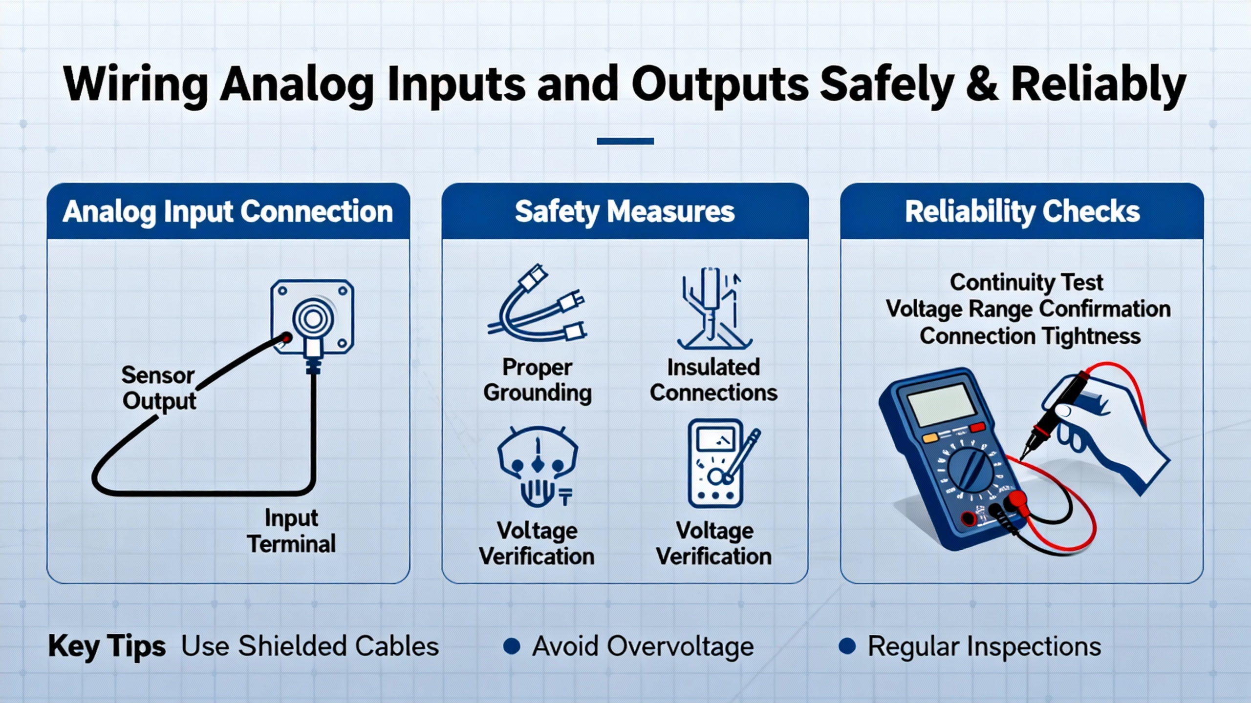
Wiring Analog Inputs and Outputs Safely and Reliably
Once the chassis and environment are under control, the wiring itself becomes the next risk point. Rockwell provides very specific field wiring rules for 1756 analog I/O modules. These rules are usually summarized in the module manuals and terminal base documentation, and they should be reflected on your wiring diagrams.
Selecting Conductors and Shielding
For analog modules, Rockwell specifies the use of shielded conductors between approximately 22 and 14 AWG with insulation rated at least to 105 ┬░F. The exact terminal loading limits depend on the terminal base module. As one example from the analog I/O documentation, when using a 1756ŌĆæTBCH terminal base, Rockwell allows no more than two conductors in a certain crossŌĆæsection range per terminal, and for a 1756ŌĆæTBS6H no more than one conductor per terminal. The manuals also caution against mixing solid and stranded wires in the same terminal.
In practice, this means that the neat multiŌĆædrop landing that looks attractive in a panel drawing may not be acceptable at the terminal base. If you need to fan out power or reference conductors to multiple field devices, it is better to do that in a dedicated marshalling terminal block where the ratings are clear, and land only the correctly sized, correctly counted conductors on the 1756 RTB. In power quality and metering applications where analog accuracy matters, treating each shield connection with discipline also matters. Shields should be terminated as indicated in the wiring diagram, and you should avoid adŌĆæhoc splices inside the cabinet.
Matching Signal Types and Ranges
The most subtle wiring mistakes are those where every conductor is landed on the correct terminal, but the signal type does not match the module configuration. The Control.com forum thread about a 1756ŌĆæIF16 input from a gas detector is a good example of this failure mode. In that case, a gas detector provided a 4ŌĆō20 mA output. The module channel was configured with an input type of 0ŌĆō5 V. The engineer set the low range to 1 V with a low engineering unit value of 4,000, and the high range to 5 V with a high engineering unit value of 20,000, essentially mapping a 1ŌĆō5 V span to a 4,000ŌĆō20,000 reading. When they simulated the channel with a milliamp calibrator, the raw counts would not increase beyond about 10,000, roughly half of the expected fullŌĆæscale.
Even though the forum excerpt does not show the final answer, it illustrates two important points. First, any wiring diagram for that channel must be read alongside the controller configuration. If the diagram is interpreted as a 4ŌĆō20 mA loop but the channel is in a 0ŌĆō5 V configuration, some piece of the design is missing or wrong. Second, scaling decisions have real consequences. In the configuration described in the forum, the engineer intended that 4,000 engineering units represent the low end of measurement and 20,000 the high end. The span between them is 16,000 units. If the input were truly linear and the mapping correct, at a midŌĆæspan value you would expect roughly 12,000 units. Seeing only 10,000 at fullŌĆæscale simulation is a red flag.
In my own commissioning work, I use a threeŌĆæstep discipline on analog channels that echoes this example. I confirm the field device output type from its datasheet and wiring diagram, I confirm that the module channel is configured for the same type and range, and then I use a calibrator to step the input from low, through mid, to high and verify that the raw counts or engineering units match the expected pattern. Any unexplained clipping, halfŌĆæscale, or offset tells me that the wiring, configuration, or scaling calculation does not match the design intent.
Power, Isolation, and Hazardous Locations
Analog modules sit at the interface between lowŌĆælevel signals and higherŌĆæenergy field circuits. The Rockwell analog I/O manual is explicit that installation and maintenance, including wiring, assembly, and disassembly, must be performed only by suitably trained personnel familiar with applicable codes and standards. It also notes that the modules are sensitive to electrostatic discharge, so handlers must discharge static to ground, use grounding straps and staticŌĆæsafe workstations, avoid touching connectors or circuit components, and store modules in staticŌĆæsafe packaging.
Another important concept from the manual is removal and insertion under power, or RIUP. ControlLogix chassis support RIUP at the chassis level, which means that the backplane can remain powered while you insert or remove modules. However, Rockwell warns that inserting or removing modules or terminal bases, or changing wiring with fieldŌĆæside power applied, can create electric arcs and explosion hazards in hazardous locations. In Class I Division 2 and Zone 2 areas, you must remove power or ensure that the area is nonhazardous before performing such actions.
In the context of power supply and UPS systems, this often shows up when someone attempts a ŌĆ£hot swapŌĆØ of an analog card monitoring battery temperature or DC bus voltage in a classified area. The correct procedure is to deŌĆæenergize the field circuit, confirm area classification, and then perform the module replacement according to the manual, returning the failed module to the manufacturer rather than attempting field repairs.
Commissioning: Verifying Connections with the Controller
A clean wiring job still needs to be proven under power. Industrial Automation Co. outlines a straightforward commissioning flow for ControlLogix controllers that also provides a good structure for verifying 1756 I/O connections. After mechanical installation, the controller is inserted in the chassis, often in slot zero, and power is applied to the chassis. The controllerŌĆÖs status LEDs are checked; green RUN and OK lights indicate normal operation, while other states indicate faults or configuration issues.
In the software layer, a project is created in Studio 5000 or RSLogix 5000, and the exact controller model is selected. The controller name, firmware revision, and IP address are set, and the controller is brought online over USB or Ethernet, depending on the model. Industrial Automation Co. emphasizes checking that the firmware matches project expectations and updating it if necessary with tools such as ControlFLASH. Once the controller is online, communication with all I/O modules and devices is verified.
For analog modules, this is where the wiring diagram meets reality. The module should appear in the I/O tree with an OK status. Each configured channel can then be observed in the tag database. For a gas detector channel like the one described in the Control.com case, I typically simulate the 4ŌĆō20 mA (or equivalent) range stepwise and observe the raw input tag and any engineering unitŌĆæscaled tag. If the wiring diagram shows a 1ŌĆō5 V mapping with 4,000ŌĆō20,000 engineering units, I expect to see readings near 4,000 at the low simulation level, around midŌĆæspan at the mid level, and near 20,000 at the high level. Any clipping at 10,000, as described in the forum, would trigger a systematic review of the wiring diagram, the module configuration, and the scaling logic.
This sort of disciplined commissioning is also essential after firmware updates or controller replacements. Since ControlLogix controllers can store programs and diagnostics in nonvolatile memory such as SD cards or CompactFlash cards, as highlighted by Industrial Automation Co., it is tempting to assume that reŌĆæinserting a card restores everything exactly. In my experience, changes to module types, firmware revisions, or wiring diagrams over time mean that every major change is an opportunity to reŌĆævalidate critical analog points.
Common Pitfalls in 1756 Wiring Projects
Across projects that tie into power protection, the same classes of mistakes appear repeatedly, and they are all preventable if you treat the wiring diagram and manual as primary sources rather than optional references.
One pitfall is assuming that all modules in the 1756 family are wired alike. Rockwell AutomationŌĆÖs support material explicitly distinguishes between the wiring diagrams for the 1756ŌĆæIF16 and 1756ŌĆæIF8. If you copy a panel drawing from a project that used an eightŌĆæchannel module and then substitute a sixteenŌĆæchannel unit without reŌĆæreviewing the manufacturerŌĆÖs diagram, it is very easy to misassign terminals or misuse shared references. The result can be channels that appear dead, channels that interfere with each other, or unexpected commonŌĆæmode paths back into sensitive equipment.
Another recurring issue is ignoring terminal and conductor limits. The analog I/O manual clearly states that only specific combinations and counts of conductors are allowed in each terminal, and that mixing solid and stranded conductors in the same clamp is not permitted. When technicians are under time pressure, they sometimes land an extra small conductor under an existing larger one to pick off an additional supply or reference. That might work on day one, but over time thermal cycling, vibration, and maintenance can loosen the connection and create intermittent faults that are almost impossible to trace. Designing the wiring diagram so that all splicing and distribution occurs in properly rated terminal blocks and landing only dedicated conductors on the RTB is the reliable strategy.
Environmental conditions create their own wiring traps. Rockwell warns that the equipment must be shielded from direct sunlight and UV radiation and used only within the specified temperature range. In real switchgear rooms with large windows or roof lights, I have seen analog modules mounted in shallow wall enclosures that bake in afternoon sun. The internal wiring insulation becomes brittle over time, and even if the module survives, the field terminations become fragile. Taking the time to specify and place enclosures where both the module and its wiring stay within environmental limits is a reliability decision, not just a compliance checkbox.
The most subtle pitfall, which the Control.com 1756ŌĆæIF16 example illustrates, is misalignment between the wiring diagram, the I/O configuration, and the field device output. A gas detector that outputs 4ŌĆō20 mA does not naturally fit a 0ŌĆō5 V voltage input configuration unless there is an explicit conversion device. Without visibility of the full thread, we cannot say exactly what was wrong in that case, but the symptom of raw counts never exceeding around 10,000 when 20,000 was configured for full scale is exactly what you would expect when a configured range and the actual signal do not match. The best practice is that every analog channel point list should include the device type, expected signal type and range, module slot and channel, and a reference back to the moduleŌĆÖs wiring diagram page. That way, electricians, engineers, and commissioning technicians can crossŌĆæcheck their work without guessing.
Finally, do not overlook cybersecurity and management aspects. Although not directly tied to wiring, Rockwell and other vendors have published case studies where manufacturers deploy platforms to unify operational technology security across sites. Wiring diagrams and I/O lists are sensitive artifacts; they describe how your critical systems are controlled. Managing them with the same discipline as your logic programs and network configurations is part of modern reliability engineering.
FAQ
Can I insert or remove a 1756 analog module while the chassis is powered?
Rockwell AutomationŌĆÖs analog I/O documentation explains that removal and insertion under power are supported at the chassis level, meaning the backplane can remain energized while you insert or remove modules. However, it also warns that inserting or removing modules or terminal bases, or changing wiring with fieldŌĆæside power applied, can create electric arcs and explosion hazards, especially in hazardous locations such as Class I Division 2 or Zone 2 areas. The practical rule is that you may only perform ŌĆ£hotŌĆØ module insertion or removal in accordance with the manual, and you must remove field power or confirm that the area is nonhazardous before touching wiring or terminal bases.
What wire size and type should I use for 1756 analog modules?
The Rockwell analog I/O manual specifies shielded conductors between about 22 and 14 AWG with insulation rated for at least 105 ┬░F for field wiring to these modules. The exact limits on how many conductors per terminal and their cross sections depend on the terminal base type; for example, some terminal bases permit at most two conductors of a certain size per terminal, while others permit only one. Mixing solid and stranded wires in the same terminal is not allowed. The safest approach is to design your wiring diagram so that every field device uses conductors and terminal loading directly supported by the specific terminal base you have selected.
Do enclosure and ambient ratings really matter for ControlLogix analog I/O?
Yes, they matter both for safety and longŌĆæterm reliability. Rockwell Automation states that these analog modules are openŌĆætype equipment intended for indoor use in suitably rated enclosures and that they are certified for ambient temperatures between 32 and 140 ┬░F and for specific pollution and overvoltage categories. The same documentation warns against direct sunlight and UV exposure and requires appropriate enclosure ratings in hazardous locations. In my experience, panels that ignore these limits show early insulation degradation, intermittent connections, and unexplained module faults, especially in hot or chemically aggressive environments. Respecting these ratings during design and installation is one of the most costŌĆæeffective reliability measures you can take.
In powerŌĆæcritical facilities, a ControlLogix rack is often the thin line between a controlled transfer and a black start. Treat the Allen Bradley 1756 wiring diagram as a contract between the manufacturerŌĆÖs intent and your plantŌĆÖs reality, and let RockwellŌĆÖs manuals and proven installation practices drive your decisions. When you align the wiring, configuration, and environment with that blueprint, your UPS, inverter, and protection systems have a solid digital foundation to rest on.
References
- https://www.slac.stanford.edu/grp/lcls/controls/global/hw/users_guides/plc/1756-in052_-en-p.pdf
- https://www.plctalk.net/forums/threads/1756-ia16-circuits-best-practice.148062/
- https://manuals.plus/rockwell-automation/1756-of8k-controllogix-analog-i-o-modules-manual
- https://tcisupply.com/how-to-build-an-allen-bradley-controllogix-plc-rack-parts-to-buy/?srsltid=AfmBOopuZNEMm8ddvqGIHWIGFZcjdkq3dYaVnOB-ibhMbXXGnTSM9oWk
- https://media.distributordatasolutions.com/AB-Symmetrix/2018q3/115e8683ea4f0f9f23900baacbf50eb0e76758a1.pdf
- https://industrialautomationco.com/blogs/news/step-by-step-guide-to-installing-a-controllogix-controller?srsltid=AfmBOoq9zho_3NaGJBbG4xmalT_cTFzXJ_tVeuHWIoegVoPAjg_UlLln
- https://control.com/forums/threads/allen-bradley-ai-card-1756-if16-not-reading-full-scale.45463/
- https://mrplc.com/forums/topic/36008-controllogix-1756-of8-wiring-help/
- https://www.roc-electric.com/Uploads/file/2018-12-10/5c0e30b5442a4.pdf
- https://literature.rockwellautomation.com/idc/groups/literature/documents/in/1756-in017_-en-p.pdf


 Videos
 News
News Applications


Leave Your Comment