When an AllenŌĆæBradley 1756 ControlLogix system suddenly ŌĆ£stops working,ŌĆØ it is rarely just a PLC problem. In powerŌĆæcritical environments with UPS systems, inverters, and protective devices, a stalled ControlLogix chassis often sits at the intersection of power quality, network health, and firmware or configuration issues. From a reliability standpoint, your goal is not only to get the controller running again but to understand why it failed and how to harden the system so the next disturbance does not take down critical loads.
Drawing on fieldŌĆæproven troubleshooting practices and guidance from Rockwell Automation documentation and independent industrial automation experts, this article walks through practical recovery methods for ControlLogix 1756 systems that appear dead, faulted, or unreachable.
How ŌĆ£1756 Not WorkingŌĆØ Shows Up in the Real World
In practice, ŌĆ£my 1756 is not workingŌĆØ usually means one of several distinct failure modes rather than a single catastrophic hardware failure. In plants and dataŌĆæcentric facilities I support, I typically see one of these patterns:
The controller is dark or stuck at powerŌĆæup, with no or inconsistent LEDs, and the process never starts. This often points toward power supply or backplane issues, sometimes triggered by upstream power events.
The controller is powered but shows a major fault or refuses to enter RUN mode after a disturbance. Rockwell documentation on major, minor, and I/O faults describes this as the controller protecting itself from unsafe conditions like corrupt memory or severe configuration errors.
I/O or networks are failing even though the CPU looks healthy. DeviceNet scanners, EtherNet/IP modules, or remote I/O adapters show error codes such as ŌĆ£NoTx,ŌĆØ E78 node errors, or repeated CIP connection resets. The process appears partially alive but blind or mute to portions of the field.
Communications with SCADA, OPC UA, or historian infrastructure are unstable. HMIs drop data, OPC clients log decoding errors, or Ignition or similar platforms show recurring timeouts and CIP resets, often under heavier data loads.
Each of these is recoverable, but the sequence matters. Jumping straight to firmware updates or controller resets without stabilizing power and communications can actually compound the problem.
The table below summarizes how these symptoms usually map to troubleshooting domains, based on Industrial Automation Co articles and multiple forum case studies.
| Symptom at the panel or HMI | Most likely problem domain | First diagnostic focus |
| No LEDs or erratic powerŌĆæup | Power supply, backplane, upstream power quality | Supply capacity, wiring, UPS/inverter rideŌĆæthrough |
| Solid fault LEDs, controller will not run | Major or I/O fault, firmware or memory issue | Studio 5000 fault logs, Rockwell fault codes |
| Missing I/O, red I/O LEDs | Module failure, DeviceNet or EtherNet/IP issues | Module health, network status indicators, cabling |
| HMI/SCADA intermittently loses tags | Network stability, CIP load, wireless links | Wireless bridge quality, CIP timeouts, driver settings |
| PLC responds slowly or times out at scale | Performance bottlenecks, data model design | Task structure, System Overhead Time Slice, tag design |
With this mapping in mind, you can work through a structured recovery path rather than chasing symptoms.

Step 1: Stabilize Power and Verify the Chassis
Before opening software tools or touching firmware, confirm that the controller and its chassis are receiving clean, adequate power. Industrial Automation CoŌĆÖs troubleshooting guidance for ControlLogix systems emphasizes that overloaded or failing power supplies can cause intermittent shutdowns that masquerade as logic or communication faults.
Start at the power supply feeding the 1756 chassis. Confirm that the power wiring is tight and correct, and that the nameplate capacity of the supply is appropriate for the total module load in the chassis. In many real systems, additional I/O or communication cards are added over time but the original supply remains, quietly drifting toward overload. The ATN ControlLogix troubleshooting course outline explicitly calls out ŌĆ£Troubleshooting ControlLogix Power Supply ProblemsŌĆØ as a core skill for this reason.
If you are in a facility with UPS systems and inverters, correlate the timing of the PLC issue with the last transfer, bypass, or battery event. A brief voltage sag that a downstream UPS rides through for IT servers can still disturb a PLC supply, especially if the inverterŌĆÖs output waveform or ground reference is not ideal for control electronics. When I see a ControlLogix system fault immediately after a recorded power event, I treat power quality as a prime suspect, not an afterthought.
With power on, inspect the chassis mechanically. Modules should be fully seated in their slots, with no visible damage or scorching. Intermittent backplane contact from a partially seated card can produce backplaneŌĆæwide symptoms that look like a controller or power supply failure. Multiple field reports of defective ASIC components on 1756 modules, especially certain manufacturing runs identified by their chip markings, describe cases in which a single bad module disrupted communications for the whole chassis until it was replaced.
If the chassis is powered but communications appear dead across all modules, a pragmatic diagnostic technique that practitioners on Oxmaint describe is the classic process of elimination: power down, remove all optional modules so only the controller and power supply remain, then reinsert modules one at a time, testing communications after each insertion. When the problem reappears at a particular slot, you have a strong candidate for a backplane or ASICŌĆærelated module failure.
From a powerŌĆæsystem perspective, the goal of this first step is clear: verify that your PLC is sitting on a stable electrical foundation before you attribute failures to logic, firmware, or networks.
Step 2: Use LEDs and Studio 5000 to Identify Fault Type
Once you have a stable, powered chassis, the next recovery step is to let the system tell you why it stopped. Rockwell AutomationŌĆÖs fault manuals for Logix5000 controllers, along with Industrial Automation CoŌĆÖs stepŌĆæbyŌĆæstep troubleshooting guide, make a consistent point: effective troubleshooting starts with interpreting LEDs and fault logs, not random trial and error.
At the hardware level, the RUN LED should be solid green when the controller is executing its program. The OK LED should also be solid green when the device is healthy, and the I/O LED should be green when I/O is being scanned and no I/O fault is present. Red or flashing patterns on these indicators signal major faults, I/O problems, or configuration errors.
Studio 5000 is your primary window into the controllerŌĆÖs fault history. Going online and opening the controller properties and fault logs allows you to see whether the last event was a major controller fault, a minor recoverable issue, or an I/O communication fault. RockwellŌĆÖs documentation on major, minor, and I/O faults explains that:
A major fault represents a severe error that typically halts program execution and pushes the controller into a faulted state. Causes include serious programming or configuration errors, corrupt memory, or resource problems. Recovery often requires clearing the fault and sometimes reloading a knownŌĆægood project.
A minor fault indicates a recoverable condition, such as outŌĆæofŌĆærange data or certain execution anomalies. Program execution can continue, but the event is logged. Best practice is to design logic to handle expected minor conditions so they do not escalate.
An I/O fault relates to communication or configuration problems between the controller and modules or network adapters. Options in the configuration allow you either to fault the controller or to continue with predefined fallback behaviors when such faults occur.
Industrial Automation CoŌĆÖs troubleshooting article stresses that a full controller reset is a last resort, used only after you have backed up the program in Studio 5000 and exhausted less invasive options. In some documented cases, resets are necessary after severe power surge events or badly corrupted firmware, but blindly resetting can erase valuable diagnostic context or even wipe an application that has not been backed up properly.
In a recovery scenario, your action sequence here is straightforward: use LEDs to determine whether you are dealing with a controllerŌĆæwide issue or a localized I/O or network problem, then use Studio 5000 to read the detailed fault codes and logs before you change anything.
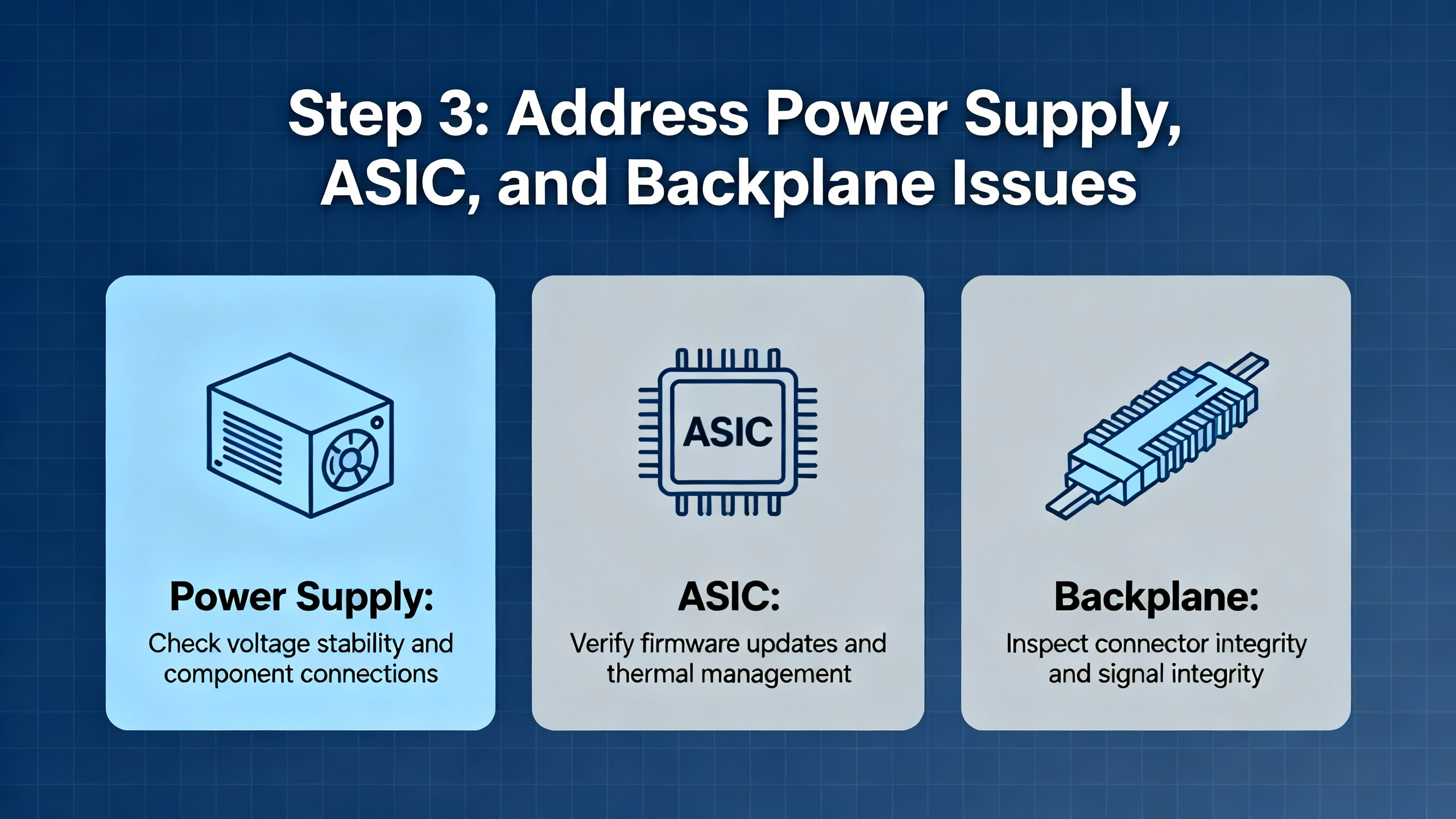
Step 3: Address Power Supply, ASIC, and Backplane Issues
If you have ruled out basic wiring and obvious firmware problems but still see widespread communication loss across the chassis, it is time to look carefully at the interaction between the power supply, backplane, and modules.
Forum discussions of 1756ŌĆæL62 systems with intermittent communication failures highlight a recurring pattern: a single module with a defective ASIC (the applicationŌĆæspecific integrated circuit handling backplane communication) can disrupt the entire chassis. In several cases, users tried swapping power supplies and backplanes, only to find that the root cause was an individual card marked with a particular ASIC that had to be replaced. Once that chip or module was replaced, the system stabilized and did not relapse.
The process of elimination method mentioned earlier is exactly how those issues were isolated. Start with just the controller and power supply in the chassis. If that configuration runs cleanly, add communication and I/O modules incrementally. When a particular module causes the entire chassis to lose communication or creates unusual backplane error behavior, you have found a likely root cause. Several engineers in these reports mention physically inspecting suspect modules for burnt or corroded areas, though ASIC failures often show no visible damage.
Power supply capacity and health are equally important. Industrial Automation CoŌĆÖs troubleshooting guidance suggests checking that the chassis supply is properly sized for the module mix, and replacing any supply that shows red fault LEDs or signs of intermittent shutdown. Overloaded supplies can shut down briefly under peak load, causing controller resets, major faults, and unexplained I/O losses that only show up under certain operating conditions.
From a powerŌĆæreliability standpoint, this is also where you audit how the PLC power is fed from your UPS or inverter system. Long branch circuits, undersized conductors, or shared circuits with highŌĆæinrush loads can cause momentary dips at the PLC that never register at the UPS monitoring level. Cleaning up that power path, or moving the PLC to a more stable protected panel, can prevent a future wave of nuisance trips.
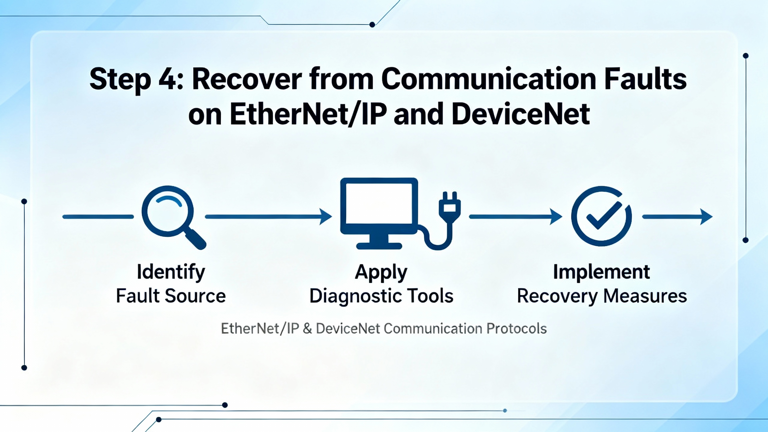
Step 4: Recover from Communication Faults on EtherNet/IP and DeviceNet
Even when the controller itself is healthy, communication modules and field networks are frequent points of failure. DeviceNet scanners, EtherNet/IP cards, and nonstandard redundancy schemes can all generate symptoms that look like a ŌĆ£dead PLCŌĆØ to operations.
EtherNet/IP modules and EN2T failures
Industrial case studies involving 1756ŌĆæEN2T modules describe situations where a failed EN2T card caused broad network issues and DeviceNet errors because higherŌĆælevel communications to SCADA and other controllers were disrupted. In those situations, replacing the failed EN2T and restoring its correct IP configuration was a central part of system recovery.
Industrial Automation Co and independent tutorial sites explain that ControlLogix Ethernet modules can be configured via RockwellŌĆÖs BOOTP utility, rotary switches, or USB and RSLinx. On legacy 1756ŌĆæENBT modules, setting rotary switches to specific values yields a fixed IP in a 192.168.1.x subnet, while newer EN2T modules often use USB and RSLinx configuration. After assigning an IP address, RSLinx and Studio 5000 can browse to the device and restore communications.
Several community threads about ControlLogix connection problems, including logs from IgnitionŌĆÖs ControlLogix drivers, show recurring messages such as ŌĆ£Reseting CIP connection,ŌĆØ timeouts on read requests, and oscillations between ACTIVE and INACTIVE connection states. These logs highlight that network stability and CIP session management are critical. If you see frequent CIP timeouts and reset attempts, investigate Ethernet cabling, switch health, and controller load rather than assuming the communication module itself is always at fault.
A control.com discussion of a 1756ŌĆæL61 system accessed over a wireless 25 Mbps Ethernet bridge provides a clear example. The system experienced intermittent communication loss to the HMI, with CIP connection open requests being rejected and socket errors on send. The recommended troubleshooting approach focused on wireless link quality, latency, and packet loss, along with HMI timeout and retry configuration. In other words, the PLC and its ENBT module were victims of network instability, not the primary culprits.
DeviceNet issues: NoTx, E78, and improvised redundancy
DeviceNet adds its own layer of complexity. In a detailed Oxmaint discussion, a ControlLogix system with 1756ŌĆæDNB DeviceNet scanners showed status indicators ŌĆ£NoTxŌĆØ and ŌĆ£E78 N##,ŌĆØ coupled with one EN2T module reported as failed. One DNB indicated ŌĆ£NoTx,ŌĆØ meaning it had powered up and initialized but saw no communication responses, typically when connected only to a short cable segment with a terminating resistor instead of the actual trunkline. The ŌĆ£E78 N##ŌĆØ status indicated that the scanner had previously established an I/O connection to a slave at node N##, but that node later stopped responding.
The root cause in that system turned out to be a nonstandard redundancy scheme: two sevenŌĆæslot chassis, each with CPU, DNB, EN2T, ProSoft, and relay output modules, tied together with Omron relays switching DeviceNet bus wires so that only one DNB was physically connected to the DeviceNet trunk at a time. Termination was also incorrect, with both DeviceNet modules carrying 120ŌĆæohm resistors at their ends and no resistor at the far end of the actual trunkline.
The recommended recovery actions in that case were grounded, not exotic. Engineers advised thoroughly tracing and documenting the wiring of CAN+ and CANŌĆæ through the relays, labeling all conductors, verifying that there was exactly one 120ŌĆæohm resistor at each extreme end of the actual trunkline, and redesigning or simplifying the adŌĆæhoc redundancy arrangement into a more standard, maintainable architecture. Replacing the failed EN2T module and restoring correct terminations were key steps in getting the DeviceNet network back to a stable state.
The lesson for recovery is clear. When a 1756 system ŌĆ£is not workingŌĆØ because I/O is missing or DeviceNet shows NoTx or E78 error codes, you must validate the physical network wiring and termination, especially if prior engineers implemented unconventional redundancy schemes with external relays or custom switching.
Step 5: Tackle Firmware and PerformanceŌĆæRelated Failures
Firmware and performance tuning can both be silent contributors to apparent system failures. Outdated firmware may introduce compatibility or stability issues, while poorly optimized task structures and communication loads can push a controller to the brink, leading to timeouts and dropped connections rather than hard faults.
Industrial Automation CoŌĆÖs dedicated guide on firmware management in ControlLogix controllers describes firmware as the lowŌĆælevel software that governs controllers, I/O modules, and communication hardware. Keeping firmware current delivers security patches, performance optimizations, new features, and bug fixes that reduce unexpected failures. Outdated firmware can create vulnerabilities, compatibility problems with I/O and network modules, and reduced functionality across the system.
The recommended firmware workflow is disciplined rather than reactive. First identify the current firmware versions via Studio 5000 or documentation and decide whether an update is necessary. Download firmware from RockwellŌĆÖs Product Compatibility and Download Center, and review release notes carefully to confirm compatibility with controller models, EtherNet/IP networks, and I/O or communication cards. Before any update, create a complete backup in Studio 5000, including project, I/O configurations, and communication settings. Use ControlFLASH to apply the update and avoid power or communication interruptions during installation. After updating, reconnect with Studio 5000 to confirm the new firmware version, run diagnostics on I/O and networks, and test critical processes. If problems occur, such as new communication issues with older I/O modules, restore the preŌĆæupdate configuration from the backup.
Interestingly, field reports do not always point to ŌĆ£newer is better.ŌĆØ In some community discussions about ControlLogix 1756ŌĆæL6x communication problems, engineers note that both upgrading and downgrading firmware have resolved issues in specific cases. That reinforces the importance of reading release notes carefully and, where possible, testing firmware changes in a nonŌĆæproduction environment before adopting them in critical systems.
Performance optimization is the other side of this coin. Industrial Automation CoŌĆÖs performance best practices for ControlLogix systems highlight task configuration, System Overhead Time Slice (SOTS), I/O and network traffic, memory usage, and firmware version as primary performance drivers. For recovery, this matters when you see timeouts and CIP resets under load, even though the controller appears healthy at rest.
Best practice is to favor periodic tasks over continuous tasks, so logic runs at predictable intervals rather than as fast as possible. This prevents continuous tasks from monopolizing CPU time and starving communications and background operations. SOTS, which by default allocates about 20% of CPU time to system functions, can be increased in communicationŌĆæheavy systems to improve data throughput, or decreased in highly controlŌĆæintensive applications to prioritize control loops.
RealŌĆæworld performance tests described on the Inductive Automation forum illustrate how communicationŌĆæheavy architectures stress ControlLogix CPUs. In one case, a single L83 controller handled roughly 106,500 tags in Ignition, consisting of tens of thousands of tags at 1ŌĆæsecond, 5ŌĆæsecond, and 60ŌĆæsecond scan rates. To keep this load feasible, engineers created communicationŌĆæfriendly bulk data structures in the PLC, grouping related values into fewer larger blocks rather than exposing thousands of individual tags. The conclusion was that moving data in bulk from the PLC and letting ITŌĆæside systems handle decoding and change detection is the only scalable way to speed up dataŌĆæheavy systems.
If your ŌĆ£1756 not workingŌĆØ complaint stems from OPC UA ŌĆ£Bad DecodingŌĆØ errors, CIP timeouts, or SCADA connection resets at scale, you may be dealing less with individual module failures and more with a system design that saturates the controllerŌĆÖs communication capacity. Performance tuning and data structuring then become part of the recovery plan.
Step 6: Structured Recovery After Major Faults and Power Events
When a ControlLogix controller enters a major fault state, especially after a power event, the temptation is to clear the fault and try to restart the process immediately. RockwellŌĆÖs fault handling manuals and Industrial Automation CoŌĆÖs troubleshooting guide advise a more structured approach.
First, capture the current state. Use Studio 5000 to go online and export the controller project and fault log before making changes. This preserves a snapshot of fault codes, timestamps, and system tags that can be invaluable in identifying root causes later.
Second, classify the fault using the major or I/O fault code. RockwellŌĆÖs consolidated fault code publications for Logix 5000 controllers categorize faults across ControlLogix 5580, GuardLogix, CompactLogix, and related families. These references indicate whether a fault stems from configuration issues, programming errors, memory problems, or module and network failures. If the code points to I/O or communication issues, focus your efforts on wiring, modules, and network diagnostics. If it points to logic or memory, examine recent program changes or firmware updates.
Third, stabilize the external environment. In a powerŌĆærich industrial or commercial environment, verify that upstream power sources, transfer switches, UPS systems, and transformers are back to normal operation and not cycling or drifting. Industrial Automation CoŌĆÖs troubleshooting examples include cases where only after reconnecting a loose network cable and observing stable operation for roughly half an hour in Studio 5000 did the engineer declare the system truly recovered.
Fourth, only consider a controller reset after you have a clean backup and understand that the reset will clear the program and unsaved data. Rockwell guidance treats reset as a last resort for severe faults such as postŌĆæsurge lockups or irrecoverable firmware corruption. After reset, the prior project must be carefully reloaded and tested.
Finally, once the system is running again, monitor it under normal operating conditions for at least one full cycle of the relevant process or shift. Use trend charts in Studio 5000, which the ATN troubleshooting course emphasizes as a tool for monitoring and validating fixes, to confirm that communication and I/O are stable.
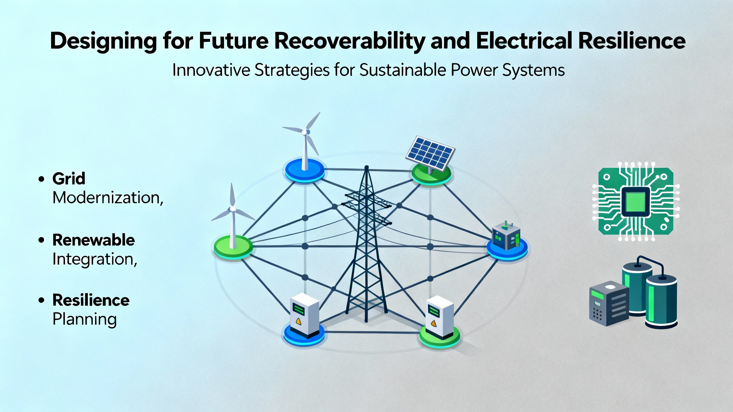
Designing for Future Recoverability and Electrical Resilience
Recovering a sick 1756 system is only half the job of a reliabilityŌĆæfocused power specialist. The real value comes from designing the control and power environment so that the next failure is less likely and easier to diagnose.
On the electrical side, ensure that the ControlLogix chassis is fed from a UPS or inverter path that is demonstrably stable during real disturbances. Avoid feeding PLCs from circuits shared with large inrush loads, and pay close attention to grounding and noise. The ATN ControlLogix course explicitly includes troubleshooting noiseŌĆærelated problems, which often surface as sporadic input failures, communication errors, or phantom faults. Shielded cabling, careful segregation of power and signal wiring, and proper bonding are relatively lowŌĆæcost measures that pay off in smoother controller operation.
From a controlŌĆæsystem design standpoint, use the performance and communication best practices documented by Industrial Automation Co and practitioners on the Inductive Automation forums. Favor periodic tasks with realistic scan times, adjust the System Overhead Time Slice for communicationŌĆæheavy architectures, and resist the urge to bring every raw point to the SCADA or OPC layer at high frequency. Group related data into structured tags and arrays to minimize PLC communication overhead, and let higherŌĆælevel systems handle detailed analysis.
In the fieldbus and network layer, avoid creative but brittle redundancy schemes like relayŌĆæswitched DeviceNet trunks. The Oxmaint case demonstrates how such adŌĆæhoc arrangements complicate troubleshooting and can collapse under fault conditions. Instead, use vendorŌĆæsupported redundancy mechanisms where needed and follow standard termination practices, such as one 120ŌĆæohm resistor at each end of a DeviceNet trunkline and not at arbitrary module locations.
Documentation is another pillar of recoverability. The ControlLogix training material from ATN places weight on managing Studio 5000 project files, documenting components, and searching project structures effectively. Industrial Automation CoŌĆÖs firmware management guide recommends maintaining detailed records of versions, dates, and changes. In a power event or major fault, your ability to restore service quickly is directly tied to the quality of your documentation and backups.
Finally, invest in skills. Industrial training programs that use real ControlLogix processors and Studio 5000 software teach technicians how to monitor inputs and outputs, interpret diagnostics, force I/O safely, and troubleshoot digital and analog modules, remote I/O, and power supplies. In facilities with complex power and control architectures, having at least one technician who is genuinely comfortable with these tools can shorten recovery time from hours to minutes.
Short FAQ
Q: What is the very first thing I should check when a 1756 chassis appears completely dead? A: Confirm that the power supply feeding the chassis is energized, correctly wired, and sized for the installed modules, and that the controller and power supply LEDs show a valid state. Industrial Automation Co emphasizes power supply capacity and health as a frequent root cause of intermittent or total controller shutdowns, especially after load expansions or power events.
Q: Should I immediately upgrade the controller firmware when I see unexplained faults? A: Not automatically. Industrial Automation CoŌĆÖs firmware guide recommends first identifying your current version and then consulting RockwellŌĆÖs Product Compatibility and Download Center and release notes to decide whether an upgrade is appropriate. Firmware changes should be tested in a nonŌĆæproduction environment when possible, and always preceded by a complete backup, because both upgrades and downgrades have resolved specific field issues in different cases.
Q: How can I tell if a 1756 moduleŌĆÖs ASIC or backplane interface might be defective? A: If removing a particular module causes chassisŌĆæwide communication to recover, or adding it causes all communication to fail, especially after you have swapped supplies and backplanes, a defective module ASIC is a strong suspect. Community reports involving 1756ŌĆæL62 systems describe exactly this pattern, with the final solution being module replacement.
Q: When does it make sense to perform a controller reset? A: A reset is a last resort for severe conditions such as persistent major faults that cannot be cleared or controller lockups after power surges or corrupted firmware. RockwellŌĆÖs fault handling documentation and Industrial Automation CoŌĆÖs troubleshooting advice are clear that you should first back up the controller project and analyze fault codes. Only after other avenues are exhausted should you reset, reload the project, and then verify I/O and communication behavior.
As a power system specialist and reliability advisor, I view every ŌĆ£AllenŌĆæBradley 1756 not workingŌĆØ call as an opportunity to strengthen both the control system and the power infrastructure behind it. If you stabilize power, respect RockwellŌĆÖs diagnostic information, and apply disciplined firmware, network, and performance practices, ControlLogix becomes not a single point of failure but a resilient part of a robust industrial power and automation ecosystem.
References
- https://www.slac.stanford.edu/grp/lcls/controls/global/hw/users_guides/plc/1756-um001_-en-p.pdf
- https://www.atn.org/allen-bradley-controllogix-plc-and-troubleshooting
- https://www.plctalk.net/forums/threads/best-practice-io-in-local-1756-chassis.108391/
- https://community.oxmaint.com/discussion-forum/troubleshooting-communication-problems-with-controllogix-1756-l62-processor
- https://www.solisplc.com/tutorials/1756-enbt-controllogix-ethernet-ip-communication-allen-bradley-plc-1756-en2t-1756-en3t-programming
- https://adegis.com/media/asset/947baf97fde5fb12aa60097585d0c01c3583e28004b38b7f75ceb565b50f766a.pdf
- https://forum.inductiveautomation.com/t/bad-decoding-error-controllogix-opc-ua/102002
- https://industrialautomationco.com/blogs/news/firmware-management-in-controllogix-controllers-a-step-by-step-guide?srsltid=AfmBOorxGNgJNfGgQSLBs3d8VT4-ohF-HEhijVHS686wHTO2glsakup1
- https://www.manualslib.com/manual/1384977/Allen-Bradley-1756-Controllogix.html?page=557
- https://www.scribd.com/document/726952249/ControlLogix-Fault-Codes


 Videos
 News
News Applications


Leave Your Comment