In industrial and commercial power systems, a variable frequency drive is one of the most effective tools you have for reducing energy use and protecting motors. When you put an ABB drive in front of a pump, fan, or conveyor, you are not just buying speed control; you are changing how that load interacts with your entire electrical and mechanical system. Done well, the result is quieter starts, lower demand charges, longer motor life, and fewer nuisance trips. Done poorly, the wrong VFD can introduce power-quality problems, motor failures, and control headaches.
From a reliability perspective, the key is to treat an ABB VFD as part of a system, not a standalone black box. The research behind this guide comes from field-proven sources such as the OSU Energy Efficiency Center, Rutgers UniversityŌĆÖs VFD retrofit work, and drive-selection guidance from manufacturers and integrators including Danfoss, AutomationDirect, Eaton, and several motor and VFD specialists. In day-to-day practice, the decision really boils down to a few critical questions: what kind of load are you driving, what does the motor nameplate say, what environment will the drive live in, and how will it connect to your power system and controls?
The sections that follow walk through those questions in a practical, ABB-oriented way. The terminology and ratings you see from AutomationDirect, Danfoss, and others map directly onto how ABB catalogs its drives, so you can use this framework when you open an ABB datasheet or selection tool.
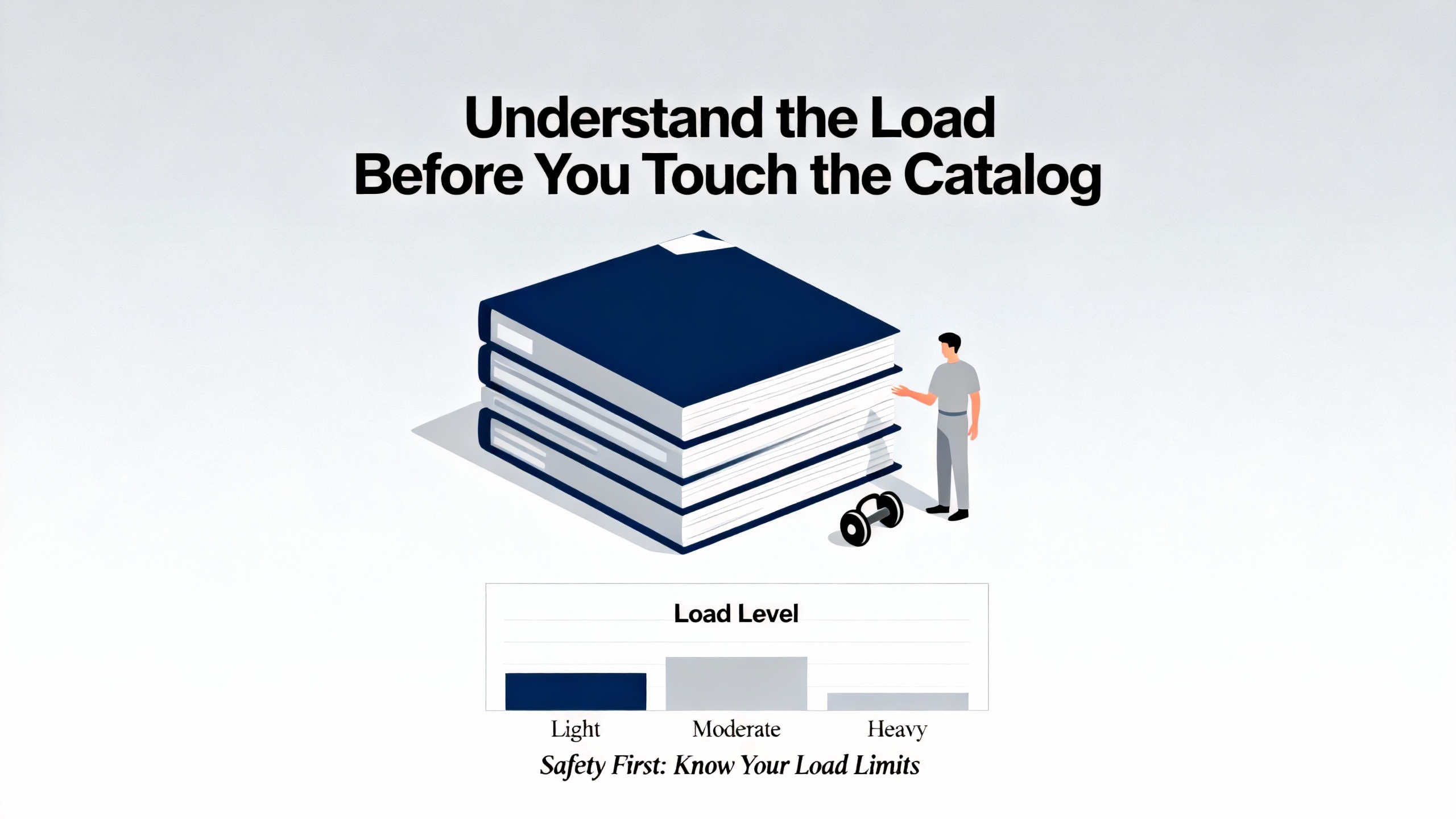
Understand the Load Before You Touch the Catalog
Load profiles and why they matter
Every good VFD selection starts at the shaft, not at the breaker. The OSU Energy Efficiency Center categorizes industrial loads into three main types: constant torque, constant power, and variable torque. This classification determines which overload rating and control mode you must look for in an ABB drive.
Constant torque loads require essentially the same torque across their speed range. Conveyors are the classic example; whether the belt moves slowly or quickly, the drive must overcome friction and move the product, so torque demand does not fall dramatically with speed. These loads are handled with drives marketed as constant torque or heavy duty, which are typically designed to supply about 150 percent of their rated current for roughly one minute, as highlighted in guidance from AutomationDirect and a Danfoss sizing note.
Constant power loads behave differently. Here, torque drops as speed increases in order to keep power roughly constant. The OSU center points to lathes and grinding machines as examples. You still treat these largely as constant torque from a VFD sizing standpoint up to base speed, but you must respect both mechanical limits and the additional stresses that come with operating at elevated speeds.
Variable torque loads are where VFDs deliver the biggest energy savings. In these applications, torque rises with the square of speed, as OSU explains for fluid-moving equipment. Fans, pumps, and blowers fall into this category. That torque-speed relationship feeds directly into the fan affinity laws: Western Michigan University and Rutgers University both emphasize that the power draw of centrifugal fans and pumps rises approximately with the cube of flow. Since flow is proportional to speed for a given system, a modest reduction in speed can yield a large drop in power.
A simple energy-savings example
Consider a supply fan in an air-handling unit that has historically run at full speed with dampers throttling airflow. If you retrofit that fan with an ABB VFD and operate it at about 80 percent speed during most of the year, the fan affinity laws say that power tends to scale with the cube of speed. Reducing speed to four-fifths of nominal drops power to roughly four-fifths cubed, which is just over half of the original draw. The Western Michigan University analysis underscores that even ŌĆ£small reductions in speed and flow can result in significant energy savings,ŌĆØ and Rutgers UniversityŌĆÖs campus-wide projects show the practical impact: premium-efficiency motors and VFDs across multiple buildings are projected to save around 2.8 million kilowatt-hours per year and avoid about 1,500 tons of carbon emissions with a simple payback of roughly three years.
These are not ABB-specific figures, but they illustrate the stakes. If most of your large fans, pumps, and cooling-tower drives sit in the ABB column on the one-line diagram, a careful load-based selection is one of the fastest ways to move the needle on both cost and reliability.
Mapping load type to ABB drive ratings
Most major drive manufacturers, including ABB, classify their drives and ratings by application type: variable torque for centrifugal fans and pumps, and constant torque for conveyors, positive-displacement pumps, and general machine loads. AutomationDirect recommends choosing drives according to a variable torque rating for fans and pumps, and a constant torque rating for applications where torque is roughly flat with speed. VFD.com makes the same distinction, noting that variable-torque drives typically require only about 120 percent overload capability for one minute, while constant-torque applications often call for at least about 150 percent.
The table below summarizes how the load categories described by OSU and HVAC engineering sources map into practical VFD choices.
| Load type | Torque vs speed behavior | Typical equipment examples | Preferred VFD rating focus |
| Constant torque | Torque roughly independent of speed | Conveyors, some mixers, many machine axes | Constant-torque or heavy-duty rating, ~150% OL |
| Constant power | Torque drops as speed rises to keep power constant | Lathes, grinders, certain machine tools | Treat as constant torque up to base speed |
| Variable torque | Torque rises roughly with the square of speed | Centrifugal fans, pumps, many HVAC blowers | Variable-torque rating, ~110ŌĆō120% OL often enough |
When you select an ABB drive, the first filter should be whether the catalog shows it as suitable for your load profile. A variable-torque fan drive may look attractive on price, but it is a poor choice for a heavily loaded conveyor that requires repeated high-torque starts.
Size the ABB Drive by Amps, Not Just Horsepower
Read the motor nameplate first
Several independent selection guides, including those from AutomationDirect, Danfoss, and VFD.com, converge on the same principle: you do not size a VFD by horsepower alone. You size it by motor current at the actual operating voltage. Danfoss emphasizes that VFDs themselves do not produce horsepower or torque; they simply need to supply enough current at the correct voltage and frequency for the motor to do its job. That means the motor nameplate is your starting point.
On the motor nameplate, the full-load amperage at the intended voltage is the critical number. Danfoss gives an example of a motor marked 230/460 volts with 13.4/6.7 full-load amps; that motor draws 13.4 amps at full load on 230 volts and 6.7 amps at 460 volts. When you pick an ABB VFD, its continuous output current rating must at least match, and usually exceed, the motorŌĆÖs full-load amps at the voltage you will actually use. AutomationDirect further stresses that while many motors are dual-voltage, drives are not inherently multi-voltage. You must choose a drive designed for the relevant voltage range, for example a family rated for the 200ŌĆō240 volt class or the 380ŌĆō480 volt class.
Another non-negotiable point from AutomationDirect is that the motors you connect to standard VFDs must be three-phase, even if your supply to the drive is single-phase. The drive internally converts AC to DC and then inverts it back to a three-phase output. A single-phase motor is not appropriate unless it is paired with a dedicated controller designed for that motor technology.
Overload and duty: matching the ABB drive to the real work
Once you have the full-load amps, you need to understand how hard you will push the motor during starts and process upsets. Most general-purpose AC drives are designed to tolerate about 150 percent of rated current for up to around 60 seconds, according to AutomationDirect, while variable-torque drives for fans and pumps often need only about 110 to 120 percent overload capability, as VFD.com notes. Danfoss points out that overload ratings are intermittent; that extra current is available for perhaps one minute out of ten, not continuously.
If you are replacing a traditional across-the-line starter on a heavily loaded conveyor or a positive displacement pump, you may see starting currents up to several times full load. AutomationDirect cautions that some legacy starter replacements effectively expect as much as 600 percent overload capability, which far exceeds what a typical constant-torque drive is designed to deliver. In such cases, you either accept longer acceleration times, re-engineer the mechanical system, or oversize the drive so that its continuous current capability is high enough that the required starting current falls within the driveŌĆÖs intermittent rating.
A simple example illustrates how this plays out. Imagine a conveyor motor with a full-load current of 40 amps at 460 volts that occasionally needs about 150 percent torque for up to a minute to break away under heavy load. A constant-torque drive with a 40 amp continuous rating and a 150 percent for 60 seconds overload rating will be running right at the edge during those events. Raising the drive selection to the next ABB frame size, perhaps with a continuous current rating in the 50 amp range, gives you margin so that 150 percent of rated drive current exceeds the motorŌĆÖs maximum expected draw. Danfoss explicitly recommends using both full-load and service-factor amps, not just nameplate full-load current, when the motor is intentionally operated into its service factor.
Single-phase in, three-phase out: de-rating for ABB drives
Many ABB drives, like their peers, can accept single-phase input and still supply three-phase power to a motor, which is especially attractive in smaller facilities with only single-phase service. However, VFD.com and an Electronics StackExchange discussion both warn that you must de-rate the drive by current when you do this. VFD.com offers a clear rule of thumb: multiply the motorŌĆÖs full-load amps by two when sizing the drive for single-phase input, and then choose a drive with at least that much output current.
That guidance comes with a concrete example. For a 10 horsepower motor with a full-load current of 28 amps, if you plan to feed the drive with single-phase power, you should select a VFD whose output current rating is above 56 amps. In practice, that often means buying a unit whose horsepower label corresponds to about a 20 horsepower motor when used on three-phase input, even though you only have a 10 horsepower motor. When you apply this to an ABB selection, you would scan the ABB catalog not for a 10 horsepower drive, but for the drive whose continuous current rating meets or exceeds those 56 amps in the correct voltage class.
From a reliability viewpoint, this deliberate oversizing when using single-phase input is not wasteful; it is essential. If you undersize a drive under these conditions, it will run thermally stressed, nuisance-trip on overcurrent, or fail prematurely.
Ensure the Motor Is Truly VFD-Ready
Motor types and markings to look for
VFDs were originally developed to remove the single-speed limitation of three-phase induction motors, and they now work with a range of AC motor technologies. eMotors Direct describes typical VFD-compatible types: AC asynchronous squirrel-cage motors are the most common industrial choice; AC synchronous permanent-magnet motors and brushless AC motors are widely used where higher efficiency or better control is required; and certain wound-rotor designs are used when very high starting torque is needed with limited supply capacity.
In practice, the easiest way to check compatibility is to look at the motor nameplate. According to eMotors Direct, motors labeled with CT/VT (constant torque/variable torque) or PWM (indicating suitability for pulse width modulation drives) are generally considered inverter-duty. Modern premium-efficiency three-phase motors produced in roughly the last decade are frequently built to withstand the high-frequency voltage spikes produced by PWM inverters, even if the labeling is not explicit. Inverter-rated motors typically have higher-grade insulation, often Class F or better.
Older motors need more scrutiny. eMotors Direct summarizes that pre-efficiency-standards motors should only be put on VFDs if they are explicitly VFD-rated, have Class F insulation or better, and the drive does not demand more than about a two-to-one turndown in constant-torque operation. Motors that meet the basic efficiency standards are often good for constant-torque operation from about half to full speed and variable-torque operation over a somewhat wider range, while NEMA Premium motors commonly support constant-torque ranges of roughly four-to-one and variable-torque ranges up to around ten-to-one or more, provided cooling and mechanical limitations are respected.
Speed range, cooling, and derating
Both eMotors Direct and contributions from experienced practitioners on The Hobby-Machinist forum highlight that running motors well below their base speed can create cooling issues, because most standard motors rely on a shaft-mounted fan to move air over the frame. At low speeds that fan moves less air. In heavy-duty applications, auxiliary blowers or derating may be required.
The Hobby-Machinist notes that many three-phase motors will operate acceptably in a speed range from about half to one and a half times their rated revolutions per minute, particularly for motors in the roughly 1,550 to 1,750 RPM band designed for 50 to 60 hertz operation. They caution that while some users push motors toward 100 hertz, staying in the 80 to 90 hertz range is often a better compromise to avoid unexpected cooling and torque issues. As an example, one contributor points out that a 2 horsepower motor rated at 50 hertz effectively provides about 1 horsepower at 25 hertz because horsepower scales with speed when torque is held roughly constant by the drive.
Totally enclosed fan-cooled motors are generally robust when used with VFDs, but the same source warns that prolonged heavy loading below about 20 hertz can create cooling problems even for these designs. For applications that demand a very wide constant-torque speed range or that must maintain minimum torque at very low speeds, it is common practice to oversize the motor or choose specialized inverter or vector motors designed for that duty. Those specialized machines are more expensive, so for many ABB VFD projects it is more cost-effective to use a standard motor, keep the continuous operating band within a reasonable range, and reserve extreme turndown conditions for brief periods.
Bearings, cables, and filters
Higher-frequency voltage pulses on VFD outputs create additional considerations beyond the motor windings themselves. eMotors Direct explains that VFD output can cause shaft voltage buildup, which can degrade bearing lubrication and eventually damage bearings. They recommend insulated bearings together with shaft grounding rings as protective measures for long-term reliability. VFD.com reinforces that inverter-duty motors often include enhanced winding insulation, and they recommend accessories such as shaft grounding rings and dedicated cooling fans in demanding applications.
Cable length between the drive and the motor also matters. According to eMotors Direct, when the motor leads extend more than about 50 feet, reflected-wave voltage spikes can increase the electrical stress on motor insulation. In those cases, adding a load reactor or a dv/dt filter is advisable. From a practical standpoint, that means if you plan to mount an ABB drive in a central electrical room and run a long feeder to a roof-mounted fan, you should budget space and cost for these filters instead of treating them as afterthoughts.
Environment, Enclosure, and Cooling for ABB Drives
Temperature, altitude, and heat rejection
Variable frequency drives are power electronics; they generate heat and are themselves sensitive to temperature. AutomationDirect notes that drives can raise the temperature inside their enclosures significantly and that thermal management is a key selection factor. Standard drive ratings usually assume operation at full capacity up to around 3,300 feet of altitude. Above that elevation, the thinner air reduces cooling effectiveness, and the drive must be oversized or derated to keep its internal components within safe temperature limits.
One practical approach in dense power rooms is to use drives that support mounting arrangements that place the heatsink fins outside the enclosure. AutomationDirect mentions ŌĆ£flange mountingŌĆØ as a feature on some units, allowing most of the waste heat to dissipate into the surrounding mechanical room rather than into a sealed panel. When you choose an ABB drive for a crowded motor control center, consider whether similar thermal management options are available. In hot electrical rooms or rooftop enclosures, it may be more economical to buy a larger drive and provide simple ventilation rather than operate a smaller drive at the edge of its thermal rating.
Dust, moisture, and corrosive environments
Chint and Eaton both emphasize that installation environment is not an afterthought. Humidity, airborne dust, corrosive chemicals, and even direct sunlight for outdoor drives should all influence the drive and enclosure choice. eMotors Direct points out that harsh conditions require appropriately rated housings, naming common enclosures such as NEMA 1 or IP20 for clean indoor locations and NEMA 4X or IP65 for washdown or outdoor applications.
If you are placing an ABB drive in a mechanical room adjacent to cooling towers, for example, it may be exposed to high humidity and chemicals from water treatment. Under those conditions, an open-style drive intended for a clean, conditioned switchgear room will not be reliable without a proper enclosure and possibly conformal coating or additional environmental protections. VFD.com notes that metallic dust can create an arc-flash hazard inside drives; that is particularly relevant in machining and fabrication shops where ABB drives may be mounted near cutting or grinding operations. Properly rated enclosures and good housekeeping become reliability measures, not just compliance exercises.
Physical size and space constraints
Eaton also reminds engineers that physical size matters. Drives must fit the available panel or motor-control-center space while still leaving room for heat dissipation and for accessories such as line reactors, filters, disconnects, and bypass contactors. Since oversizing an ABB drive can be desirable for thermal reasons, single-phase de-rating, or future load growth, it is wise to check not only the electrical ratings but also the frame dimensions early in the design, rather than discovering during installation that your chosen frame does not fit the allotted cubicle.
Power Quality, Integration, and Safety
Harmonics and upstream power quality
While VFDs save energy at the load, they can pollute power upstream. Eaton explicitly identifies harmonic mitigation as a major consideration, because PWM drives distort the current waveform. VFD.com makes a similar point, especially in the context of small shops and phase conversion, and recommends adding line reactors or drives with integrated harmonic mitigation. These accessories can be mounted in the same cabinet as the drive, preserving footprint while improving power quality.
From a reliability standpoint, unmanaged harmonics can cause overheated transformers, nuisance trips on protective devices, and interference with sensitive equipment. When specifying ABB drives on a system fed by UPS units, generators, or long feeders, it is prudent to ask whether drives with built-in harmonic mitigation or external filters are warranted, particularly for higher horsepower units.
Control integration and communications
According to Eaton, ease of integration with existing control systems is another key selection criterion. Drives should interface cleanly with panel layouts, I/O, and communication networks. eMotors Direct encourages buyers to think ahead about software and communications, recommending that you look for drive platforms with industrial Ethernet or fieldbus interfaces, configurable inputs and outputs, and options for integrated logic or simple programmable control. This is directly relevant when you deploy ABB drives into plants with existing PLCs, building automation systems, or remote monitoring requirements.
On the human side, you must decide whether operators will control speed and start/stop locally on the drive keypad, through a hardwired speed reference such as a panel-mounted potentiometer, or via control signals from automation systems. VFD.com notes the options of analog signals like 4ŌĆō20 milliamp and serial protocols like Modbus and other industrial networks.
An Electronics StackExchange discussion provides practical guidance on basic control wiring. The contributors recommend using the driveŌĆÖs own start and stop functions for normal operation and reserving external contactors for safety-related rapid disconnection. They also note that additional relays are only needed when the drive must interface with other machine controls. Reliability is improved when the ABB drive is allowed to manage its own start-stop sequences rather than being repeatedly energized and de-energized through upstream contactors.
Braking, stopping, and safety interlocks
For applications with overhauling loads or where rapid stopping is required, eMotors Direct highlights the role of dynamic braking. When a heavy load keeps the motor spinning after power is removed, the motor acts as a generator, and the DC bus voltage in the drive can rise dangerously unless that energy has somewhere to go. Dynamic braking modules dissipate that energy as heat in a resistor. eMotors Direct cites a braking module that can provide about 25 percent dynamic braking torque and up to 100 percent instantaneous braking torque, illustrating how much stopping power these accessories can add.
On machine tools and similar equipment, The Hobby-Machinist contributors stress that safety interlocks and anti-restart protection must be preserved when adding a VFD. Many three-phase lathes use contactors and power relays to prevent automatic restart after a power loss and to coordinate interlocks. If an ABB drive is wired directly to the spindle switch without preserving those protective functions, you can inadvertently create unsafe behavior. In critical systems, retaining mechanical contactors for lockout and emergency-stop functions while letting the drive handle normal modulation is often the most robust approach.
Branch-circuit overcurrent protection is another non-negotiable. Electronics StackExchange responses and manufacturer guidelines agree that proper fusing or circuit breakers ahead of the drive must be selected in accordance with the driveŌĆÖs documentation. If you encounter a VFD brand that does not provide clear manuals, the same contributors suggest treating that as a red flag and favoring suppliers who do, which is an area where major manufacturers, including ABB, typically excel.
Walking Through a Practical Selection
Pulling these threads together, imagine you are selecting an ABB VFD for an existing centrifugal pump in a commercial building. The pump currently runs at constant speed with throttling valves and you want variable-flow control to trim energy use.
You start at the motor. The nameplate shows the rated voltage and full-load amps. Suppose it reads 460 volts, three-phase, and a certain full-load current. Using the guidance from Danfoss and AutomationDirect, you decide that the AB BdriveŌĆÖs continuous current rating must be at least equal to that full-load current, with some margin. Because this is a centrifugal pump, you classify the load as variable torque based on the OSU and HVAC engineering descriptions, so you look for a variable-torque rating on the ABB drive. VFD.comŌĆÖs advice indicates that a one-minute overload capability of about 110 to 120 percent of rated current is typically adequate for this kind of load, and the pump manufacturer confirms that starting torque demands are modest.
Next, you consider the electrical supply. The building has three-phase service, so you do not need the single-phase de-rating that VFD.com discusses, and you can select a drive in the same horsepower class as the motor, as long as the current ratings align. If instead you were converting from single-phase supply to a three-phase motor, you would follow the rule of doubling the motorŌĆÖs full-load amps and selecting the ABB drive according to that higher current figure, even if the resulting horsepower label on the drive is larger than the motor nameplate.
You then review the environment. The pump and motor sit in a warm mechanical room with occasional moisture, but no washdown. You expect some dust. Guided by Chint and eMotors Direct, you choose an enclosure rating equivalent to a basic indoor protection level suitable for this environment, possibly a panel-mounted drive in a NEMA 1 or IP20 enclosure. Because the building is near sea level, you have no altitude derating concerns, but AutomationDirectŌĆÖs reminders about enclosure heating prompt you to ensure there is sufficient ventilation and space around the drive. If space is tight or heat loads are high, you might look for an ABB frame that supports through-the-wall mounting so the heatsink sheds heat outside the panel.
You also check the distance from the proposed drive location to the motor terminals. If that cable run is approaching or exceeding 50 feet, eMotors DirectŌĆÖs guidance suggests adding a load reactor or dv/dt filter to protect the motor insulation. Given that this pump is in a basement mechanical room with a short run, you decide no additional filtering is required.
Finally, you plan the control and protection scheme. You decide to accept a speed signal from the building automation system and to use the ABB driveŌĆÖs start and stop inputs, in line with the recommendations seen in the Electronics StackExchange discussion. Branch-circuit protection is sized according to the drive manual. Because the pump does not have an overhauling load and you do not need aggressive deceleration, you do not add a dynamic braking module. Had this been a vertical-lift application with a heavy overhauling load, the dynamic braking capability described by eMotors Direct would have been a stronger consideration.
With these steps, what could have been a simple ŌĆ£match horsepower and priceŌĆØ exercise becomes a structured, reliability-driven selection process grounded in the same principles used by Danfoss, Eaton, Chint, and others, and directly applicable to ABBŌĆÖs VFD portfolio.

Short FAQ
Can I run a single-phase motor from an ABB VFD?
Standard VFDs, including those discussed by AutomationDirect, are designed to supply three-phase output. They can often accept single-phase input, but the motor they feed must be three-phase. If you currently have a single-phase motor on a critical application and want speed control, the usual reliability-oriented path is to replace the motor with a three-phase unit that is VFD-compatible and then select an ABB drive sized by full-load amps at the appropriate voltage.
Should I oversize an ABB VFD for reliability?
You should oversize a drive intentionally when the application demands it. Danfoss and VFD.com both point out situations where upsizing makes sense: high-overload constant-torque applications, drives fed from single-phase input, or installations at high altitude or elevated temperature where cooling is limited. In those cases, choosing the next larger ABB frame so that real operating currents fall within conservative continuous and overload limits is a reliability investment, not waste.
When do I need an inverter-duty motor with an ABB drive?
According to eMotors Direct, modern premium-efficiency motors are often built to handle VFD duty, especially when labeled CT/VT or PWM. You should consider a clearly inverter-duty motor when you need a wide constant-torque speed range, when the motor will operate at low speeds for long periods, or when cable runs are long and voltage spikes are a concern. In all cases, inspecting the nameplate for insulation class and VFD-related markings, and applying appropriate bearings, grounding rings, and filters as recommended by VFD.com and others, aligns the motor with the demands that ABB drives will place on it.
As a power system specialist and reliability advisor, I see the most resilient ABB VFD installations come from this kind of disciplined selection: understand the mechanical load, size by motor amps and overload, respect environment and power quality, and treat motors, drives, and protection as one integrated system rather than separate boxes on a drawing.
References
- https://eec.oregonstate.edu/motor-control-technologies
- https://greenmanual.rutgers.edu/ec-variable-frequency-drives/
- https://wmich.edu/facilities/engineering/variable-frequency-drives-hvac-systems
- https://www1.eere.energy.gov/manufacturing/tech_assistance/pdfs/motor.pdf
- https://www.uaex.uada.edu/environment-nature/water/docs/IrrigSmart-3241-B-Variable-frequency-drives.pdf
- https://admisiones.unicah.edu/uploaded-files/MkcbtA/0OK002/variable_frequency-drives-for__dummies.pdf
- https://library.automationdirect.com/how-to-select-a-variable-frequency-drive/
- https://www.controleng.com/how-to-select-configure-and-tune-industrial-motor-drives/
- https://www.csemag.com/how-do-you-specify-the-best-motor-it-depends/
- https://americas.fujielectric.com/what-is-the-most-important-thing-to-consider-when-selecting-a-drive-for-a-motor/


 Videos
 News
News Applications


Leave Your Comment