Modern industrial and commercial power systems lean on protection relays to detect abnormal conditions and isolate faults before they cascade into costly downtime. ABBŌĆÖs digital relaysŌĆöwell represented by the Relion 615 seriesŌĆöcombine fast protection elements, programmable logic, communications, and selfŌĆæsupervision. When they operate unexpectedly or fail to operate, the challenge for a UPSŌĆōinverterŌĆōswitchgear environment is separating a true system fault from a settings issue, wiring error, power quality disturbance, or internal device condition. This guide translates field practice into a structured, repeatable approach for ABB protection relay fault identification, drawing on recognized practices in IEEE C37 and IEC 61850, guidance from ABB technical manuals, and troubleshooting knowŌĆæhow from sources such as Schneider Electric and the Delgado Relay Protection Reference.
What ABB Protection Relays Actually Do
A protection relay is the systemŌĆÖs decisionŌĆæmaker. It measures current and voltage via CTs and VTs, applies protection algorithms such as overcurrent, differential, or distance, and issues trip, alarm, or block signals to the breaker and automation system. In ABBŌĆÖs digital platforms, the relay continuously selfŌĆæsupervises its hardware and application logic. A protection operation reflects the relayŌĆÖs judgment about the primary system. An internal fault alarm reflects the relayŌĆÖs judgment about itself. Keeping these two categories separate is the heart of good troubleshooting.
In practice, an ABB relayŌĆÖs output is a product of five ingredients: input signals, power and time synchronization, protection settings and logic, coordination with neighboring devices, and a healthy physical interface to the breaker and communications network. Troubleshooting that respects this chainŌĆöfrom inputs to actuationŌĆöprevents blind setting changes and shortens restoration.
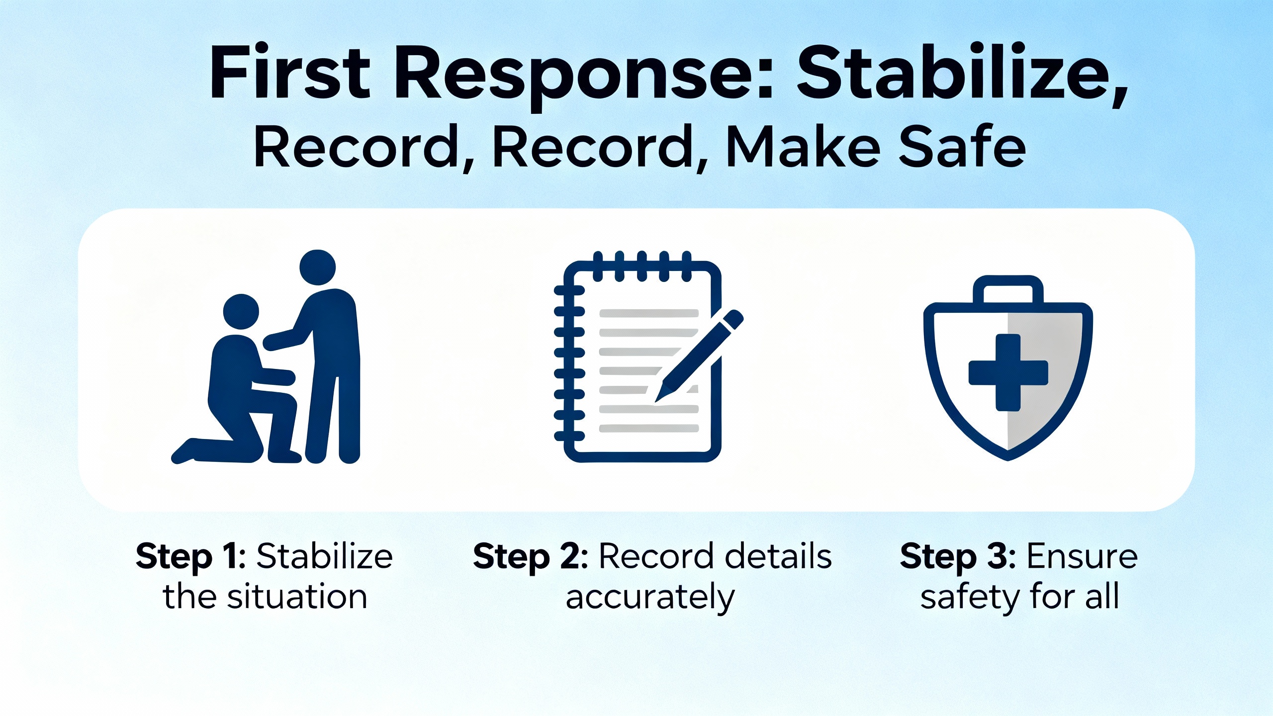
First Response: Stabilize, Record, Make Safe
When a relay trips or alarms, immediate actions influence whether you will later reach a clear root cause. Begin by stabilizing the system so it is safe to investigate. Preserve evidence by noting the time to the minute, saving the relayŌĆÖs event list and disturbance records, and capturing the present settings file. Confirm whether an actual fault occurred by correlating breaker operation, upstream and downstream relays, and any UPS or inverter events. Do not reset or clear memory until you have exported the logs and settings; those files are your timeline. If you must restore service quickly, take a conservative approach: place sensitive elements in alarmŌĆæonly mode under a documented risk assessment, or transfer the load to a known stable source such as a static bypass, then return to systematic diagnosis.
A StepŌĆæbyŌĆæStep Workflow That Finds Root Causes
Effective relay troubleshooting is a methodical loop: understand, gather, verify, test, and document. In commissioning and postŌĆæevent reviews, this loop consistently resolves even stubborn issues.
Understand the device and the scheme
Start with the exact relay model and firmware, the protection elements applied, and the surrounding scheme. A feeder overcurrent relay protecting a UPS output bus behaves differently than a transformer differential relay tied into breaker failure and arcŌĆæflash reduction logic. Consult ABBŌĆÖs technical manual for your model and the singleŌĆæline and threeŌĆæline drawings for the bay. Trace logic interlocks and permissives in the configuration file so you know which conditions enable a trip.
Gather context and evidence
Collect the relayŌĆÖs event list, any fault records or oscillography, and the current settings file. Note related alarms in the UPS, inverter, or downstream drives; harmonics or voltage sags recorded there often explain nuisance trips. The Delgado Relay Protection Reference emphasizes documenting symptoms, settings, and test results; that habit makes future incidents easier to resolve and supports change control.
Verify power and communications
Measure the relayŌĆÖs auxiliary supply at its terminals. A drooping supply causes resets, comms misbehavior, and sporadic internal alarms. Verify time sync health; inconsistent time stamps complicate coordination analysis. For serial networks such as Modbus over RSŌĆæ485, ensure a true daisyŌĆæchain topology, proper endŌĆæofŌĆæline termination and biasing, and consistent port settings. Field experience and practitioner reports show that starŌĆæwired RSŌĆæ485 segments and missing termination often produce ŌĆ£frozenŌĆØ HMIs and intermittent comms alarms that are misattributed to the relay.
Inspect settings and coordination
Compare pickup and time delays against the coordination study and the present system configuration. Incorrect grading between an ABB feeder relay and downstream breaker trip units is a leading driver of unnecessary outages. For motor circuits, Schneider Electric notes that undervoltage pickŌĆæups set too high, thermal overload factors misapplied around the 125% fullŌĆæload current basis, and instantaneous elements set without regard to inrush commonly produce nuisance trips under normal starts. ReŌĆæconfirm CT and VT ratios and polarity, particularly after maintenance; a swapped polarity can look like reverse current and block or misdirect tripping.
Check input and output circuits
Verify that measured currents and voltages at the relay match clampŌĆæmeter readings and that all terminations are tight and landed on the correct terminals. For output circuits, prove the trip path: measure that the relay asserts the expected voltage or current during a test and that the breakerŌĆÖs trip coil is healthy. Many ŌĆ£relay did not tripŌĆØ events turn out to be finalŌĆæelement issues in the trip circuit, not logic errors in the relay.
Analyze event and disturbance records
Event lists show the sequence and timing of element pickups and outputs. Disturbance records reveal waveform features such as DC offset, harmonics, and CT saturation. If a relay trips during a motor start and the record shows high harmonic content with current decaying as expected, the issue points to an instantaneous element set too low, not a true short circuit. If an overcurrent element trips slowly yet upstream trips fast, the timeŌĆæcurrent curves are misgraded. ABBŌĆÖs selfŌĆæsupervision alarms appear here as well; treat those as device state indicators and handle separately from protection operations.
Prove behavior with secondary injection
Secondary injection confirms whether the relay responds to known inputs as intended. Inject near the boundaries, just inside and just outside the pickup, and verify the measured times align with the characteristic. Practitioner guidance stresses testing functional paths, not just isolated terminals: drive inputs and verify that the mapped logic energizes the intended output and the right physical circuit. This catches wiring swaps and missing interlocks that automated scripts might miss. With digital relays, repeated ŌĆ£exact pickupŌĆØ hunting adds little value; focus on element enable conditions, digital inputs and outputs, power supply margins, and communications health.
Escalate appropriately and document
If internal faults persist, record the fault identifier, the relay model and firmware version, and all recent changes. Attempt a controlled restart once, verify auxiliary power quality and thermal environment, and then contact ABB support with the collected evidence. Close the loop by storing the settings, tests, and corrective actions in your maintenance records.
Symptoms You See, Causes You Find, Actions That Work
The same symptoms repeat across plants because the physics and the standards are the same. The table below pairs common ABB relay symptoms with likely causes, first checks, and a fast confirmation test.
| Symptom in the field | Likely cause | Check first | Fast confirmation test |
| Trip during motor start with no damage found | Instantaneous overcurrent set too low, undervoltage setpoint too high for start sag | Compare inrush expectation to settings; confirm undervoltage relative to the common 90% rated guideline noted by NEMA and Schneider Electric | Inject stepped current around the pickŌĆæup; review disturbance record for starting profile |
| Missed trip on a clear fault | Pickup too high, CT saturation or polarity error, logic block active | Verify CT ratio/polarity and element enables; reŌĆæplot timeŌĆæcurrent curves | Secondary injection at fault level with logic flags visible |
| Frequent trips during voltage sags | Undervoltage element too sensitive; poor rideŌĆæthrough coordination with UPS/inverter | Compare setpoint/time delay to system sags; review UPS sag logs | Adjust threshold and delay within study margins and observe event logs |
| Comms alarms or HMI freezes | RSŌĆæ485 star wiring or missing termination/bias; inconsistent serial settings | Inspect wiring topology and terminations; confirm baud, parity, stop bits | Scope the bus or use a protocol analyzer; correct topology and bias |
| ŌĆ£Internal faultŌĆØ or selfŌĆæsupervision alarm | Device selfŌĆæmonitoring detected a hardware, firmware, or critical configuration issue | Record code, model, firmware, temperature, and supply; attempt one restart | Update to a supported firmware and escalate to ABB if alarm returns |
| Trip asserted but breaker did not open | Trip circuit wiring issue, coil or DC supply failure | Measure relay trip output and coil circuit continuity | Trip test with the breaker open and meter on the coil circuit |
Settings That Drive Most Misoperations
Protection performance lives or dies by a few pivotal settings. The coordination study sets the goals; small deviations in implementation often explain big problems.
Undervoltage thresholds deserve particular care. As Schneider Electric notes, NEMA guidance warns against extended operation below about 90% of rated voltage. Setting a pickup above that benchmarkŌĆösuch as 220 V on a 230 V motor circuitŌĆöcan cause a relay to declare a sag unacceptably low during a normal start, creating a nuisance trip. Pair the threshold with a sensible time delay to ride through starts and short sags while still detecting sustained undervoltage that threatens equipment.
Thermal overload settings on motor protection must match the relayŌĆÖs design. Some relays expect you to set nameplate fullŌĆæload current and include the 125% factor internally; others require you to apply the factor yourself. Setting a relay to 50 A on a 60 A motor penalizes every heavy load step with trips; setting to approximately 156% doubleŌĆæcounts and undermines protection. Follow the deviceŌĆÖs manual, use the nameplate, and record the rationale.
Instantaneous overcurrent elements must ride through inrush. Even without a soft start or VFD, motors can produce starting currents several times fullŌĆæload current. Element pickup, any harmonic restraint, and time delays should be proven in the field with real starts and validated by disturbance captures. With soft starters or drives, inrush is lower and the pickup can safely be lower, but so can the tolerance for measurement error during harmonic distortion.
Coordination and grading margins deserve a fresh look whenever system fault levels or breaker settings change. Selectivity is not just a plotting exercise; it is what decides whether a local fault trips a local breaker quietly or takes down the whole section. Regrade when utility fault levels change, when a UPS or inverter is added, or when protective device types are swapped.
The summary below links each pitfall to impact and fix.
| Setting pitfall | Impact in service | Practical fix |
| Undervoltage set too high | Nuisance trips during starts and minor sags | Tie pickup to realistic sag behavior and add delay per study |
| Thermal overload misapplied | Trips under normal load or inadequate protection against heating | Follow the relayŌĆÖs method around the 125% FLC basis and the nameplate |
| Instantaneous OC too low | Trips on inrush or transformer energization | Quantify inrush; add harmonic restraint; validate with captures |
| Misgraded time delays | Wrong device trips first; widespread outages | ReŌĆæplot curves with actual fault levels and breaker curves |
| CT ratio/polarity wrong | Elements block or misoperate | Confirm on drawing and with a quick polarity test |
| Logic interlock not met | Protection blocked during real faults | Trace enable conditions; use logic monitors during tests |
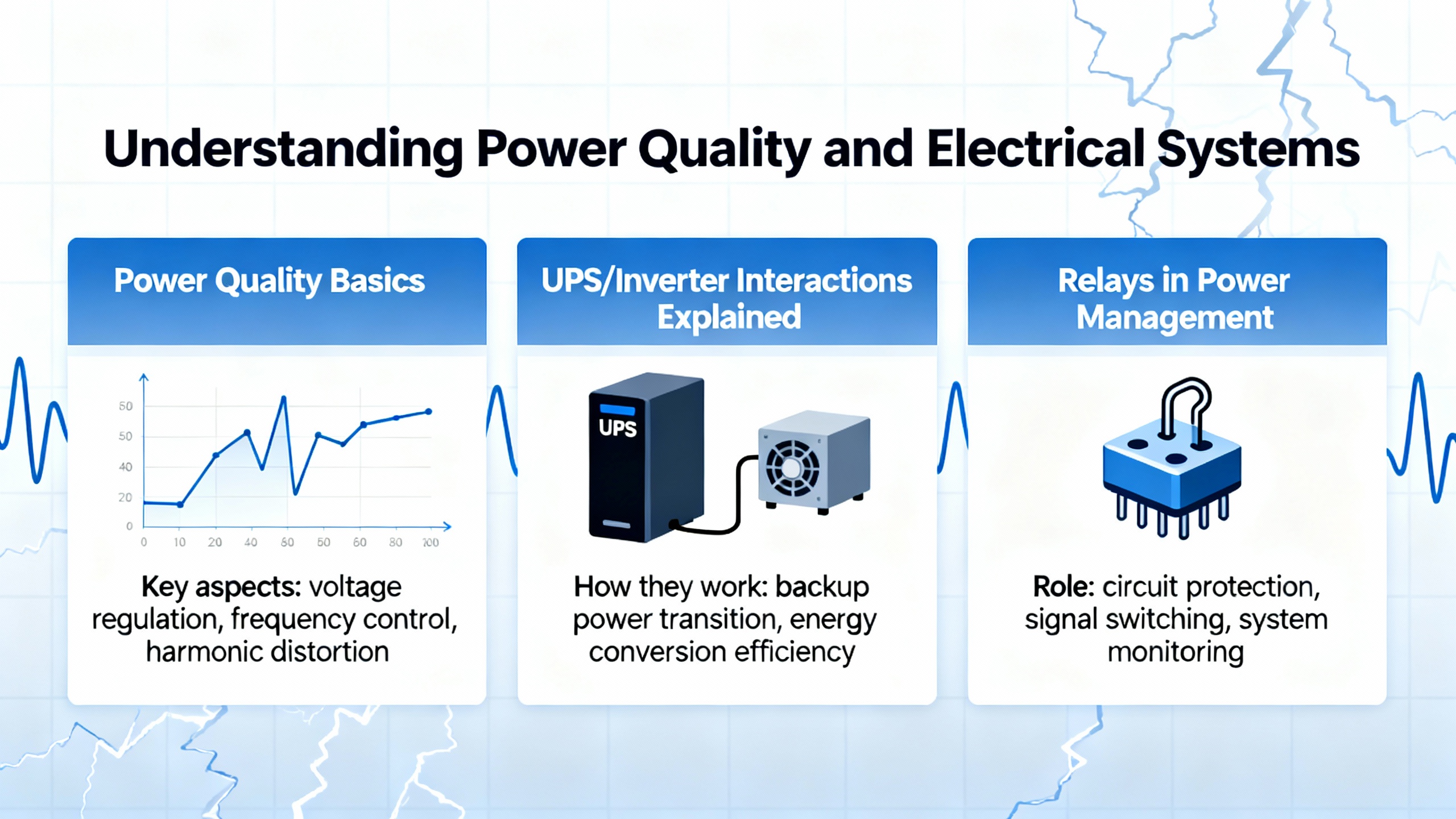
Power Quality, UPS/Inverter Interactions, and ABB Relays
In UPSŌĆæbacked and inverterŌĆæfed systems, power quality is not a side note. Harmonics, notches, and nonŌĆæsinusoidal waveforms distort measured currents and voltages. A digital relayŌĆÖs trueŌĆæRMS measurement and filtering help, but thresholds and delays still need context. Voltage sags during transfers or motor starts triggered from the inverter bus can be misread by undervoltage elements that were tuned for utilityŌĆæfed sine waves. HarmonicŌĆærich currents during drive acceleration can tickle instantaneous elements.
Treat these environments as you would any mixedŌĆæsource system. Review event logs across the UPS, inverter, and relay to correlate sags, frequency deviations, and harmonics with trips. Add surge protection and appropriate filtering where transients or supraharmonics appear. Where the UPS rideŌĆæthrough policy and relay undervoltage element argue with each other, align the settings so that rideŌĆæthrough and protection work toward the same objective: keep the system running through the temporary disturbance, then act decisively for sustained abnormal conditions.
Communication Faults Are Not Always Relay Faults
Many ABB relay ŌĆ£faultsŌĆØ are actually wiring and topology issues on the communications network. The EngŌĆæTips community and field practice converge on a few truths for RSŌĆæ485. Use a single daisyŌĆæchain trunk, not a star. Terminate both ends, and only the ends. Provide bias resistors so idle lines have a known state. Keep stubs short to avoid reflections. Align baud rate, parity, stop bits, and slave addresses across all devices. A single defective node or miswired pair can hold the entire segment hostage and produce frozen HMIs and intermittent timeouts. For noisy or long runs, use repeaters, galvanic isolation, or fiber. When you need high robustness, ABBŌĆÖs fiberŌĆæbased options or EthernetŌĆæbased IEC 61850 reduce the pitfalls that plague copper serial links.
Internal Fault Alarms: Meaning and Response
An internal fault alarm indicates the relayŌĆÖs selfŌĆæsupervision detected a condition that calls its health into question. ABBŌĆÖs manuals for the 615 series describe how the relay enters a safe state, asserts selfŌĆæsupervision, and logs codes when such conditions arise. Treat this as a device event that sits besideŌĆöbut separate fromŌĆöprotection operation. Record the code, model, and firmware version. Verify auxiliary supply and temperature. Perform one controlled restart to clear a transient condition. If the alarm persists, update to a vendorŌĆæsupported firmware and open a technical case with ABB. Include the event logs and any disturbance records to shorten the backŌĆæandŌĆæforth. Do not continue service with repeated internal alarms; that is a reliability and safety gamble you do not need to take.
Testing That Builds Confidence
Commissioning and maintenance testing of ABB relays should mirror the real world, not just checkboxes. Functional testing that drives inputs through the configured logic to energize the real outputs catches wiring and mapping errors that automated relayŌĆæonly scripts miss. Test near the decision thresholds, just inside and just outside, to confirm both operate and restrain actions. For electromechanical devices in legacy panels, pickup points and times drift with age; for digital relays, the hardware either works or it does not. As instructors and practitioners emphasize, the dominant failure modes in digital relays are often A/D converters, auxiliary power supplies, I/O hardware, and settings, not the protection algorithms. Put your test time where it pays: prove the health of inputs and outputs, check power margins, and scrutinize settings and coordination. Automation is valuable, but it should serve your test intent, not replace it.
EndŌĆætoŌĆæend tests add unique assurance when communicationsŌĆæassisted schemes, transferŌĆætrip logic, or time tagging matter. Where an endŌĆætoŌĆæend setup is impractical, capture and compare disturbance records across relays under the same event with stable time synchronization. The point is to verify that the systemŌĆönot just the deviceŌĆödoes the right thing.

Care, Maintenance, and Lifecycle Practices
Relays do not live in a vacuum. Temperature, humidity, dust, and vibration degrade connectors and power supplies. Periodic inspection and cleaning, torque checks on terminals, and verification of fan airflow in adjacent equipment reduce nuisance behavior. Maintain a disciplined firmware policy: standardize on vendorŌĆæsupported versions, test upgrades in a pilot asset, and keep the rollout and rollback paths documented. Calibrate test equipment so your conclusions are trustworthy. Archive every settings change with a reason. Train technicians on the rationale behind settings, not just the keystrokes. And keep spares for critical models so a rare hardware failure does not turn into a prolonged outage.
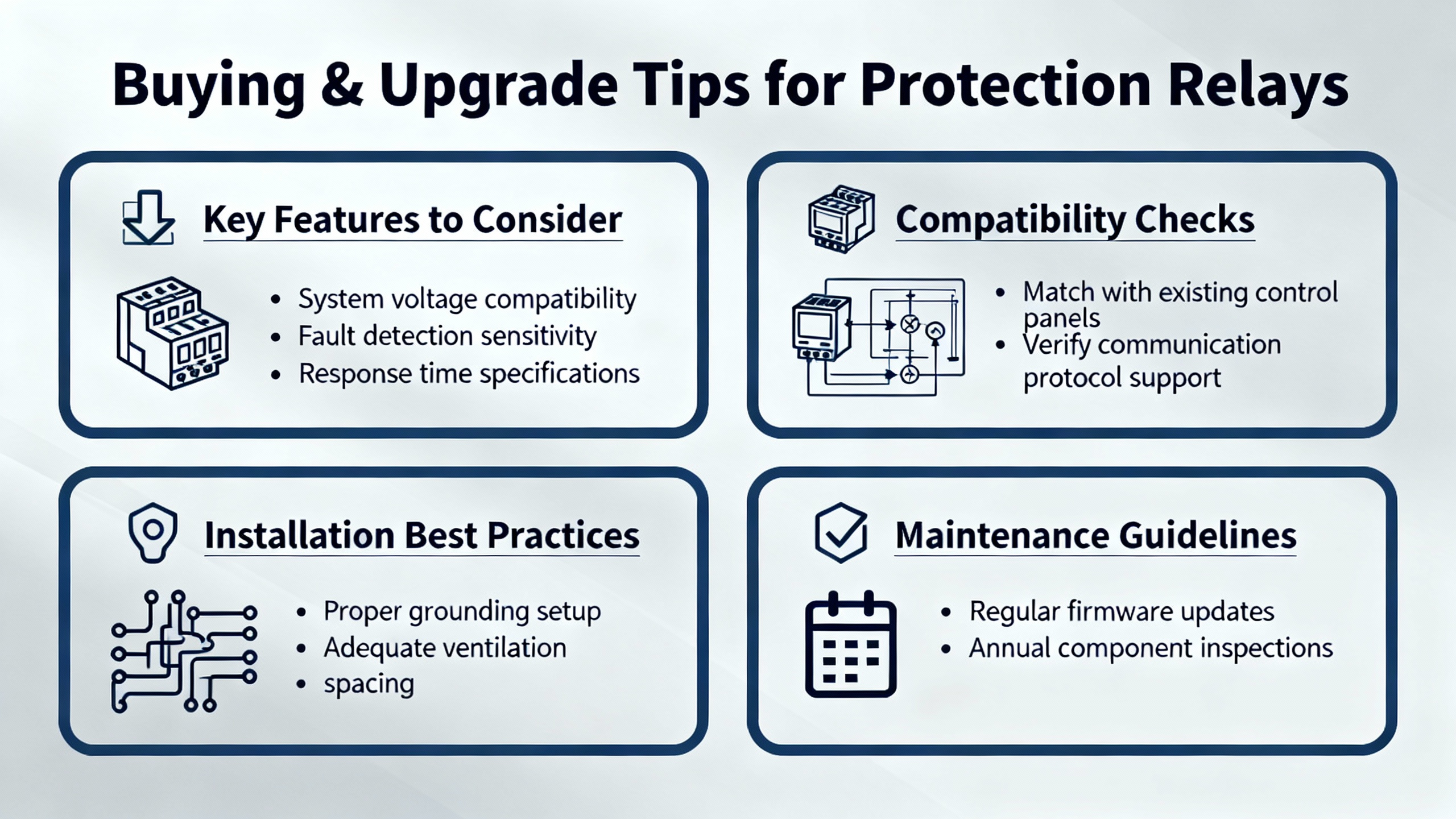
Buying and Upgrade Tips for ABB Protection Relays
The best troubleshooting is the kind you rarely need to do, and that starts with fitŌĆæforŌĆæpurpose selection. Select elements that cover your risksŌĆöfeeder overcurrent, transformer differential, breaker failure, and arcŌĆæflash mitigation where personnel exposure exists. Ensure communications match your plant architecture; IEC 61850 brings speed and flexibility in substations, while DNP3 or Modbus may align with existing SCADA. Verify event memory depth and disturbance recording support; postŌĆæevent visibility is a lifesaver. Confirm selfŌĆæsupervision features and diagnostics so internal faults are unambiguous. Look for time synchronization options compatible with your facility. Match CT/VT requirements to what is installed, including burden and accuracy at your fault levels. Evaluate cybersecurity features if the relays participate in a networked control system. Finally, weigh vendor support, training availability, and the installed base in your region; those soft factors determine how quickly you can get expert help when it matters.
Quick Reference: Data Worth Capturing Before You Touch Settings
When an ABB relay misoperates, gather a standard set of data before making changes. This habit preserves evidence and anchors your decisions.
| Data to capture | Why it matters |
| Relay model, serial, firmware version | Ties behavior to known issues and vendor support paths |
| Current settings file and last approved study extract | Baselines actual against intended configuration |
| Event list with timestamps | Reconstructs the sequence of picks, trips, and blocks |
| Disturbance records for the event window | Provides waveform evidence of sags, harmonics, and saturation |
| Recent changes and environmental notes | Correlates issues with configuration or site conditions |
| CT/VT ratio and polarity checks | Confirms measurement scaling and current direction assumptions |
Takeaway
ABB protection relays are as reliable as the system around them. Most ŌĆ£relay problemsŌĆØ trace back to mismatched settings, misapplied coordination, wiring and I/O issues, communications topology errors, or power quality disturbances from UPS and inverter dynamics. A disciplined processŌĆögrounded in IEEE C37 principles, ABB manuals, and experienceŌĆöquickly separates true faults from false alarms. Preserve evidence, prove behavior near thresholds, and treat internal fault alarms as device health events that warrant vendorŌĆæaligned action. Do the simple things well, and you will spend more time improving reliability and less time chasing ghosts.
FAQ
What is the fastest way to tell if a trip was a true fault or a nuisance operation?
Start with the relayŌĆÖs event list and any disturbance record. If the current waveform shows an inrush profile or a shallow voltage sag during a motor start, settings are the likely culprit. If the waveform shows sustained overcurrent with little decay, you probably had a genuine fault. CrossŌĆæcheck with downstream device states to confirm selectivity.
How should I set undervoltage elements in motor and UPSŌĆæbacked systems?
Anchor the pickup to realistic sag behavior and the general NEMA guidance against extended operation below about 90% of rated voltage, then add a time delay that rides through starts and short transfers. Schneider ElectricŌĆÖs guidance is a useful reference, and your coordination study should define the final delays.
My RSŌĆæ485 link to an ABB relay keeps dropping. Is the relay defective?
Not necessarily. Many dropouts come from wiring and topology, not the device. Use a single daisyŌĆæchain, terminate both ends, add bias resistors, keep stubs short, and ensure all serial parameters match. Replace or isolate any node that drags down the bus. For harsh environments or long distances, prefer fiber or EthernetŌĆæbased IEC 61850.
An ABB relay shows an internal fault alarm. Can I clear it and keep running?
Treat internal alarms as device health events. Record the code, model, firmware, and environmental conditions, perform one controlled restart, verify auxiliary power, and update to a supported firmware if applicable. If the alarm returns, escalate to ABB support. Do not operate indefinitely with recurring internal fault alarms.
Do digital relays drift and require periodic recalibration of pickups and times?
Digital relays do not drift the way electromechanical relays do. Focus your maintenance testing on functional behavior, input and output health, auxiliary power margins, and settings verification. Secondary injection should validate operation and restraint near thresholds, and records should be archived for trend analysis.
WhatŌĆÖs the single best investment to reduce nuisance trips?
Align the protection settings with the actual system behavior and the coordination study, then prove them with functional tests and realŌĆæworld captures. Most nuisance trips stem from a few sensitive thresholds and misgraded delays; fixing those pays back immediately in uptime.
Sources Consulted
This guide reflects field practice informed by ABB technical manuals for the Relion 615 series, the Delgado Relay Protection Reference, Schneider Electric guidance on motor protection settings, practitioner experience reported on EngŌĆæTips, and handsŌĆæon relay testing principles described by training providers and application notes. Where standards are cited, IEEE C37 and IEC 61850 are the primary references governing protective functions and substation communications.
References
- https://www.academia.edu/39043052/Facilities_Instructions_Standards_and_Techniques_Volume_3_8_Operation_Maintenance_and_Field_Test_Procedures_for_Protective_Relays_and_Associated_Circuits_Previously_Titled_Field_Testing_Procedures_for_Protective_Relays
- https://ww2.jacksonms.gov/scholarship/JdWsVf/270006/AbbProtectiveRelayApplicationGuide.pdf
- https://mail.yuin.edu/fulldisplay/Nuqkhe/2S9053/Protection%20Relay%20Training%20Courses.pdf
- https://www.pnnl.gov/main/publications/external/technical_reports/PNNL-36067.pdf
- https://do-server1.sfs.uwm.edu/dl/6896Z9225E/lib/8698Z8E/the-relay_testing_handbook__principles_and__practice.pdf
- http://www.dc.narpm.org/libweb/mL1071/6001027/Abb%20Protective%20Relay%20Application%20Guide.pdf
- https://www.plctalk.net/forums/threads/ab-safety-relay-circuit-troubleshooting.120973/
- https://seasons4.net/wp-content/uploads/2012/11/ABB-Fault-codes.pdf
- https://search-ext.abb.com/library/Download.aspx?DocumentID=2UCD101058&LanguageCode=en&DocumentPartId=&Action=Launch
- https://www.allpcb.com/allelectrohub/troubleshooting-relay-circuits-a-practical-guide-for-electrical-engineers


 Videos
 News
News Applications


Leave Your Comment