Modern ABB variable frequency drives (VFDs) are exceptionally reliable, yet even wellŌĆædesigned systems can trip, alarm, or fail when installation, environment, or configuration drift away from best practice. As a power system specialist who supports pumping stations, HVAC plants, and production lines, I see the same pattern repeatedly: the fastest path back to uptime comes from decoding the fault precisely, validating the electrical and mechanical fundamentals, and applying parameter and hardware corrections that address the true root cause. This guide distills proven troubleshooting methods, fault code interpretation, measurement techniques that actually work on PWM outputs, and practical repair and prevention strategies aligned with ABBŌĆÖs guidance and respected industry sources.
What ABB Drives Are Doing and Why Faults Matter
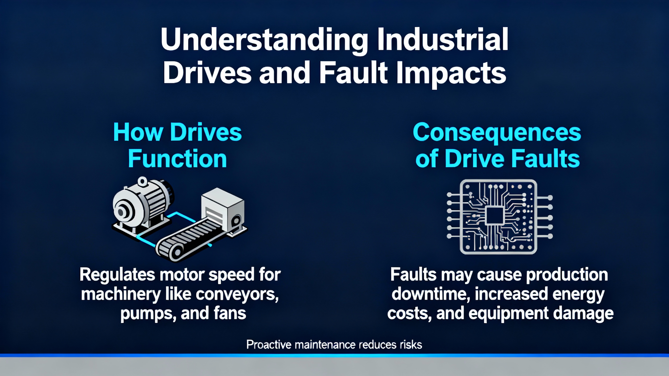
An ABB VFD controls AC motor speed and torque by adjusting the frequency and voltage of its output. Families such as ACS310, ACS355, ACS580, and ACS880 appear across water and wastewater, material handling, and building services. A drive is never operating alone. It is part of a system that includes incoming power quality, grounding and bonding, shielded VFDŌĆærated cables, motor insulation integrity, load mechanics, and control logic. A fault in any of these layers will surface at the drive, and interpreting that signal correctly is the key to eliminating repeat downtime.
Where to Read Faults and Events in ABB Drives
ABB drives expose fault codes, warnings, and an event history with timestamps via the keypad or local HMI. On higherŌĆæend families such as ACS580 and ACS880, ABB Drive Composer adds a deeper diagnostic view, parameter backup and comparison, live trending, and convenient export of logs. Timestamps help you correlate trips to process changes, starts and stops, weatherŌĆædriven load shifts, or upstream power events. Pull the history first, note the exact code, context, and when it happens (for example, at start, under load, during decel, or at random idle), and only then start changing settings or swapping parts.
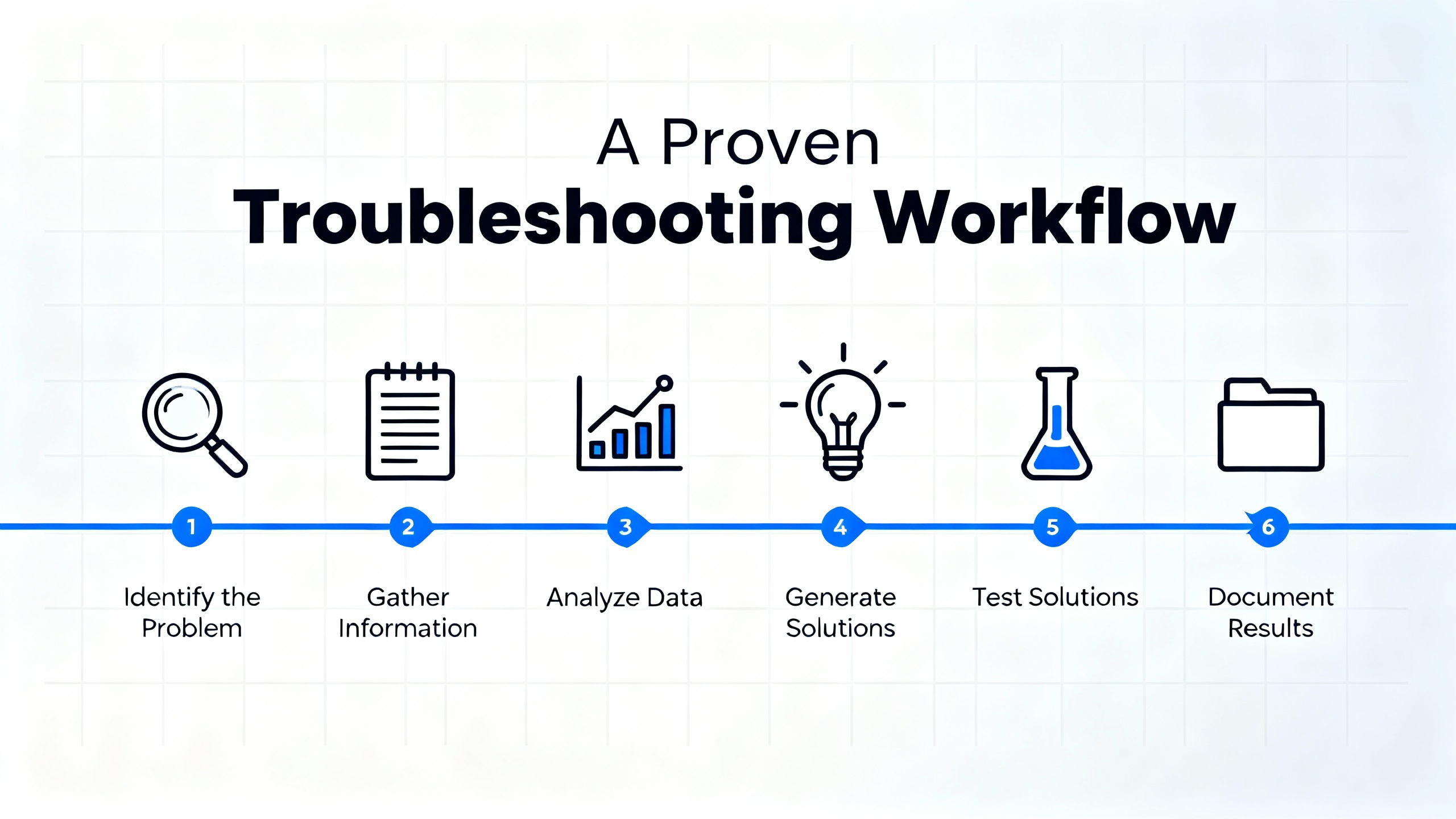
A Proven Troubleshooting Workflow
Start with safety, especially with stored energy on the DC bus. Follow your facilityŌĆÖs lockout/tagout procedures and ABBŌĆÖs manual to ensure the bus has discharged before touching power components. Then capture the exact fault code and the event history. Before diving into parameters, stabilize the basics: verify threeŌĆæphase input is present and balanced, check that lugs are torqued to specification, inspect grounding and shielding, and confirm that cable runs and motor terminations are correct. ReŌĆæcommission the essentials by entering motor nameplate data, verifying control mode (scalar V/Hz or vector), setting realistic acceleration and deceleration ramps for your load inertia, and saving changes to nonŌĆævolatile memory. If the motor has not been identified for vector control, perform an autoŌĆætune or motor ID procedure per the ABB manual. If a fan, pump, or blower might be coasting when a run command is issued, enable speed search (often called a flying start) so the drive synchronizes to the rotating shaft instead of fighting it.
For mechanical verification, decouple the load when feasible and confirm that the motor rotates freely. Binding, misalignment, and seized bearings trigger overcurrent faults as the drive tries to accelerate. For electrical verification, use instruments that read VFD outputs correctly. A trueŌĆæRMS, VFDŌĆærated meter avoids misleading low readings on pulseŌĆæwidthŌĆæmodulated waveforms. Measure where it is safe and meaningful, such as the DC bus and input side, and combine that with a megohmmeter test of the motor and output cable when groundŌĆæfault or leakage symptoms appear. Finally, change one variable at a time and retest under consistent conditions to see cause and effect. When internal faults persist after baseline corrections, escalate to ABB service for bench testing, firmware updates, and, if indicated, repair or replacement.
Common ABB Faults, Root Causes, and Field Fixes
The following table summarizes frequent ABB faults and the checks that most efficiently separate configuration issues from mechanical or electrical problems. The code names and remedies align with practical guidance from ABB, Delta Automation, and field experience.
| Code or condition | What you see | Likely root cause | Quick checks | Corrective action |
| F0001 Overcurrent | Trip during acceleration or on load spikes | Mechanical binding, tooŌĆæaggressive acceleration, wiring errors, or shorted output | Spin the load by hand, inspect output wiring and motor leads, compare drive amps to motor FLA | Lengthen acceleration, correct mechanics and wiring, review torque/current limits, consider heavyŌĆæduty sizing where needed |
| F0002 Overvoltage | Trip on deceleration or when stopping highŌĆæinertia loads | Regeneration into the DC bus because decel is too fast or no braking path exists; high mains voltage | Check incoming line voltage, review decel time, verify braking resistor wiring if used | Extend decel, add or size a dynamic braking resistor, correct line voltage issues |
| F0003 Undervoltage | Trip at start or random sags | Missing phase, loose lugs, weak source, or blown fuses | Confirm stable threeŌĆæphase input and balance, tighten connections, inspect and replace fuses if present | Restore stable input power and correct terminations; address power quality problems upstream |
| F0005 Device Overtemperature | Trip after run in warm or dusty area | Blocked airflow, failed fans, poor clearance, or ambient too high | Inspect heatsink, fans, and vent paths; check ambient and enclosure heat rise | Clean and restore airflow, replace failed fans, add clearance or external cooling as needed |
| F0010 Motor Stalled | Speed fails to rise and current climbs | Mechanical jam, undersized motor, or tooŌĆælow torque limits | Decouple and test motor, check nameplate match, test windings | Fix mechanical issues, rightŌĆæsize the motor/drive, tune torque/boost parameters |
| F0022 Earth (Ground) Fault | Trip immediately or under load with leakage indications | Cable or motor insulation breakdown or contamination | Megger motor and output cable, inspect terminal blocks and moisture ingress | Dry or replace the culprit, improve cable routing and shielding, correct grounding |
| F0023 Internal Fault | SelfŌĆætest failures or repeat internal code | Sensor/circuit fault or IGBT stage problem | Power cycle, reload parameters from backup, verify firmware | BenchŌĆætest, repair, or replace through ABB or qualified service |
| Communication/parameter mismatch | Loss of network control or erratic operation | Wrong node address/baud, bad cable, EMI, or parameter lockouts | Verify control and reference source selection, fieldbus settings, and cable shielding | Correct settings, replace damaged cables, improve grounding/shielding, and update firmware |
Commissioning and Parameters That Make or Break Reliability
The fastest route to a stable system is getting the commissioning foundation right. Enter motor voltage, frequency, fullŌĆæload amperage, and base speed directly from the nameplate. Choose a control mode aligned to the application: scalar V/Hz is simple and robust for pumps and fans, while vector control improves torque response and efficiency for conveyors, cranes, and compressors. Tune acceleration and deceleration ramps to match load inertia so the drive neither trips on overcurrent during start nor on overvoltage during stop. For fans or blowers that may be spinning when you hit Start, enable speed search so the drive finds the actual shaft speed and resumes control smoothly. Ensure the command source and speed reference are exactly what you intend, whether local keypad, discrete inputs, analog signal, or fieldbus. If the HMI will not accept edits, check user access level and parameter lock settings. After changes, explicitly store the configuration so it survives a power cycle, and keep an offline backup. ABB Drive Composer on families such as ACS580 and ACS880 makes backups and comparisons far faster and reduces the chance of ŌĆ£mysteryŌĆØ settings.
The table below links common setup items to their realŌĆæworld symptoms and the practical fix.
| Parameter area | Why it matters | Symptom when wrong | What to check or set |
| Motor nameplate data | Correct current, torque, and slip model | Nuisance overcurrent or poor torque | Set voltage, frequency, FLA, and base speed per nameplate |
| Control mode | Defines torque response and stability | Weak start or oscillation | Choose V/Hz for variable torque loads and vector for constantŌĆætorque applications |
| Accel/decel ramps | Aligns drive dynamics with inertia | Trips during start or stop | Lengthen ramps for heavy loads; avoid abrupt decel on regenerating loads |
| Braking hardware | Provides a path for regenerative energy | Overvoltage on decel | Add and enable a braking resistor when loads are high inertia |
| Speed search (flying start) | Matches a coasting motor to drive output | Trip when starting a windmilling fan | Enable speed search in the selected control mode |
| Command/reference source | Determines who starts and what sets speed | ŌĆ£No responseŌĆØ to HMI or PLC | Set Local versus Remote and select the proper reference |
| Access level and locks | Prevents accidental edits but can block changes | Changed values do not stick | Unlock or raise user level, then store to nonŌĆævolatile memory |
| Configuration backup | Ensures fast recovery from resets | Long rework after defaulting | Export and archive parameter backups per asset |
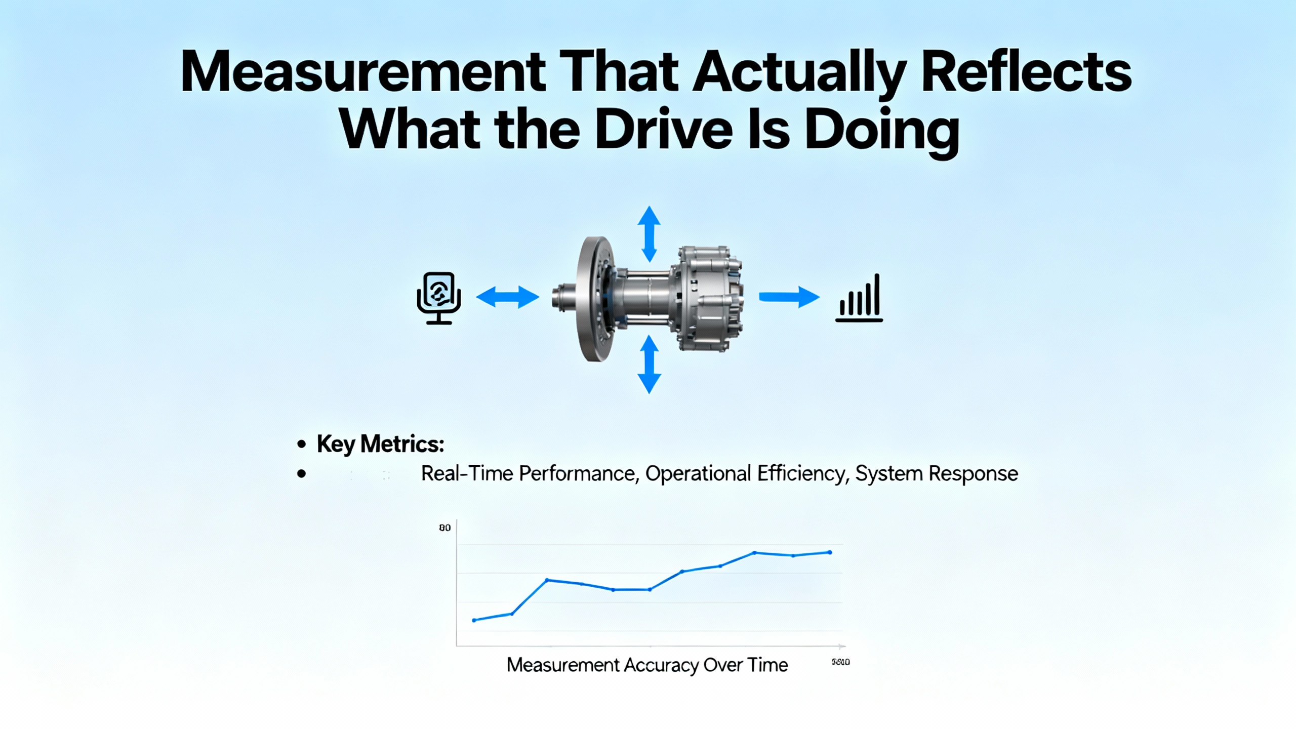
Measurement That Actually Reflects What the Drive Is Doing
Clamp meters not designed for PWM waveforms routinely underŌĆæread VFD output current, creating the illusion of low amps while the driveŌĆÖs own display reports high values. A trueŌĆæRMS, VFDŌĆærated meter is the baseline for meaningful readings. Use it on the input side and DC bus where appropriate, and interpret motorŌĆæterminal readings with care. For suspected ground or insulation faults, a megohmmeter tells the truth. Readings in the range of 2 to 20 megohms indicate poor insulation; immediate corrective work is warranted. Values below about 2 megohms point to severe breakdown, and you should not operate the system in that condition. ABB guidance summarized by repair specialists recommends replacement when insulation resistance falls below roughly 10 megohms. Combine these tests with visual inspection for moisture, oil residue, and discolored conductors. When you see recurring groundŌĆæfault trips with measurable leakage current and visible cable cracking or terminal carbon tracks, the most reliable fix is to replace compromised cabling with shielded, VFDŌĆærated conductors and clean, dry terminations.
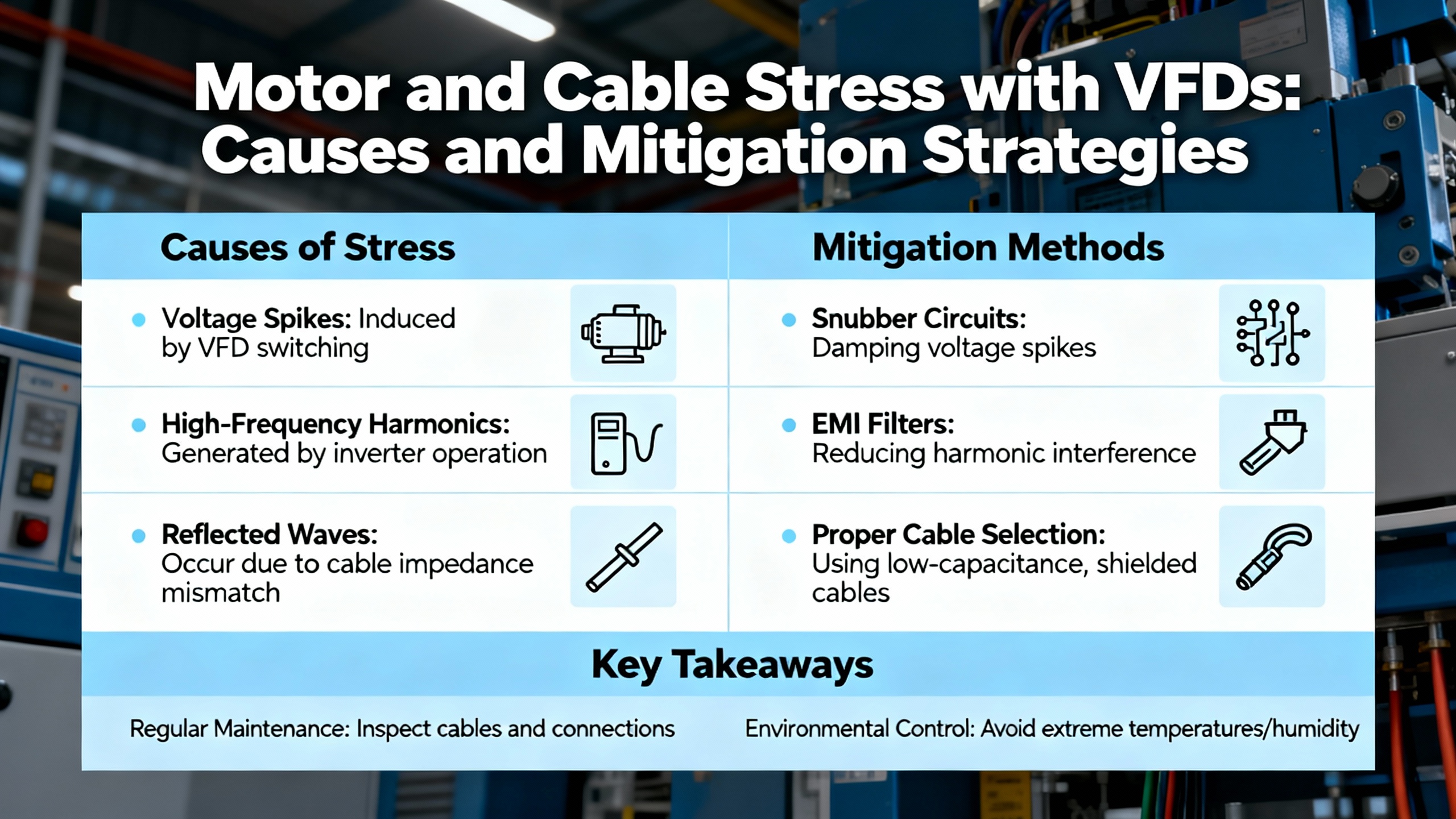
Motor and Cable Stress with VFDs, and How to Mitigate It
Fast IGBT switching produces voltage reflections that are amplified by long cable runs and motor impedance. At the motor terminals, spikes can reach roughly two to four times line voltage. Motors designed and labeled for VFD duty per NEMA MG 1 Parts 30 and 31 withstand these stresses better; older motors may not. Output filters and proper cable selection limit peak stress, reduce bearing currents, and improve electromagnetic compatibility. Thermal behavior also changes with VFD operation. At low speeds, a totally enclosed fanŌĆæcooled motorŌĆÖs shaftŌĆæmounted fan moves less air, which raises winding temperature. A simple rule of thumb from motor practice applies here: every increase of about 18┬░F over rated ambient roughly halves expected insulation life. If you must run for extended periods at low speed under load, consider separate blowers, speed adjustments that keep fan airflow up, or a mechanical change such as gear reduction to move heat outside the motor envelope. These measures, along with clean air paths and dust control, materially extend both drive and motor life.
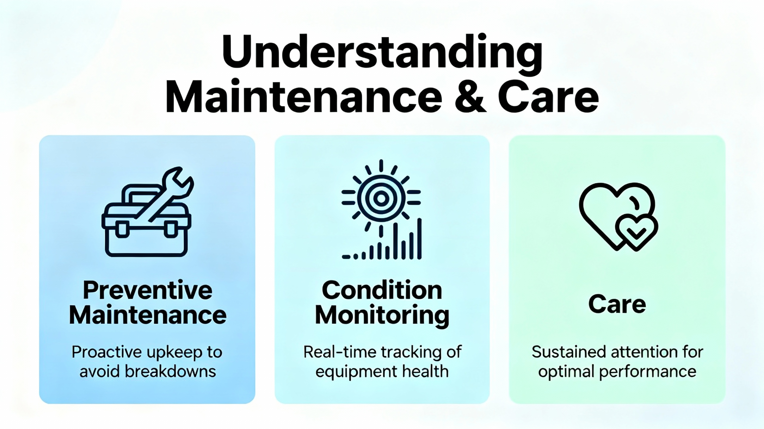
Preventive Maintenance, Condition Monitoring, and Care
Drives thrive in clean, cool, and electrically quiet spaces. Keep vents and heatsinks free of dust buildup, verify that fans move air, and maintain adequate clearance inside enclosures to avoid hot spots. Monitor ambient temperature and humidity, since moisture is a reliable path to leakage and ground faults. Make a habit of reviewing event logs with timestamps, because recurring warnings often precede full trips and let you fix small problems before they stop production. When you operate in harsh environments, plan periodic insulation checks with a megohmmeter to catch degradation early. Retaining parameter backups and change logs dramatically shortens recovery from accidental resets or corrupted settings. When your operation justifies it, conditionŌĆæmonitoring tools bring predictive maintenance into reach by trending current, temperature, and vibration to spot fault signatures long before a shutdown.
The table below groups core preventive checks and the decision context that turns them into reliability.
| Area | What to monitor | Practical notes |
| Cleanliness and airflow | Heatsink fins, fan operation, and vent paths | Dust and oil restrict cooling; clean before overtemperature faults appear |
| Thermal conditions | Ambient around drives and motor temperatures | Elevated temperature accelerates insulation aging; adjust airflow or add cooling where needed |
| Connections and terminations | Lug torque, terminal condition, and cable strain relief | Loose lugs mimic undervoltage and trip under load; reŌĆætorque per spec after thermal cycles |
| Insulation health | Megger readings for motors and output cables | Replace or remediate when readings trend down toward 10 megohms; do not run below about 2 megohms |
| Event history | Warnings and trips correlated with process changes | Timestamps reveal patterns tied to starts, stops, and power dips; fix causes early |
| Firmware and backups | Software versions and offline parameter sets | Keep versions current and backups handy to recover after service or resets |
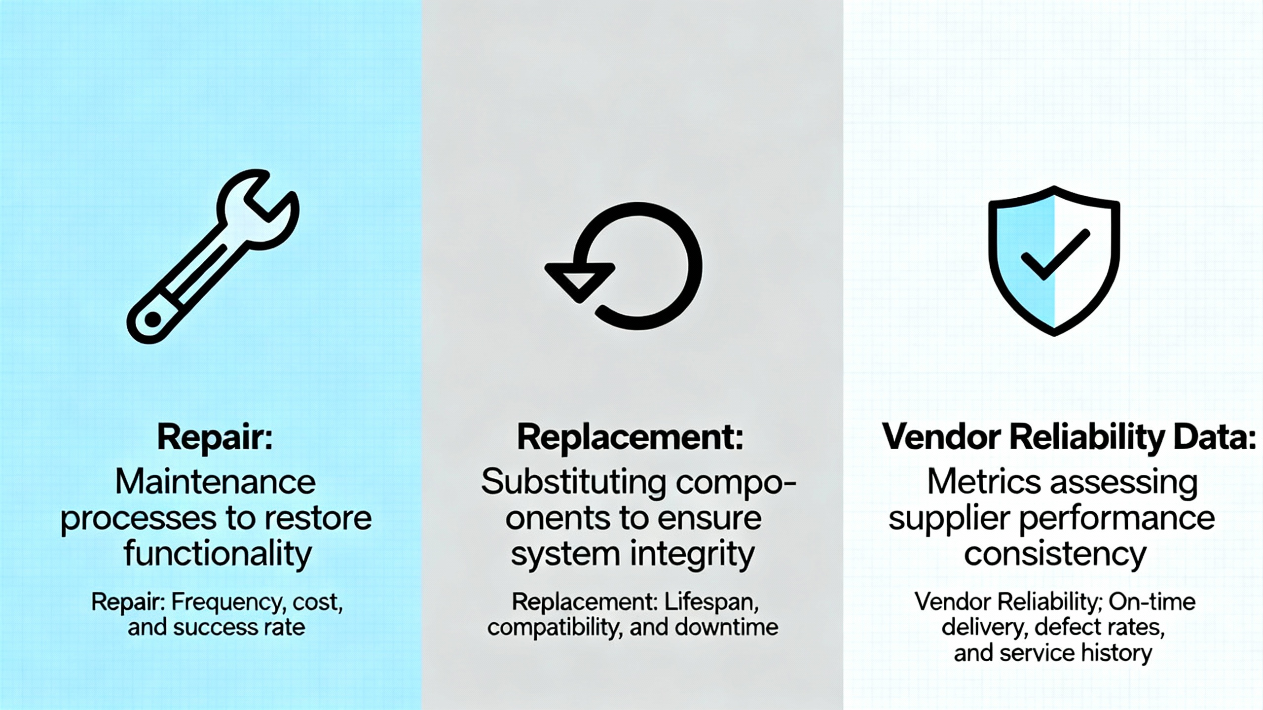
Repair, Replacement, and Vendor Reliability Data
When a drive presents a persistent internal fault after you have validated input power, wiring, parameters, and motor health, the failure is often inside the currentŌĆæsensing path or IGBT stage. In these cases, the most timeŌĆæeffective path is a bench test with ABB tools, followed by repair or replacement through ABB or a qualified service center. Your decision balances criticality, lead time, and the cost of downtime. This is where vendor reliability data proves its value. ABB publicly describes Reliability Demonstration Testing and Accelerated Life Testing practices. Reliability Demonstration Testing confirms that a sample population survives for at least a target life under accelerated stress without failing. Accelerated Life Testing drives units to failure at various stress levels to estimate actual life and identify material constants. Depending on the required confidence and reliability levels, sample counts often range from about seven to twenty for RDT and seven to sixty for ALT. ABBŌĆÖs reliability container testing compresses about ten years of life into a few months through temperature cycling and other controlled stresses. When you compare drive options, ask for published test approaches, sample sizes, and the mission profile assumptions behind the numbers, then match them to the conditions your equipment actually sees.
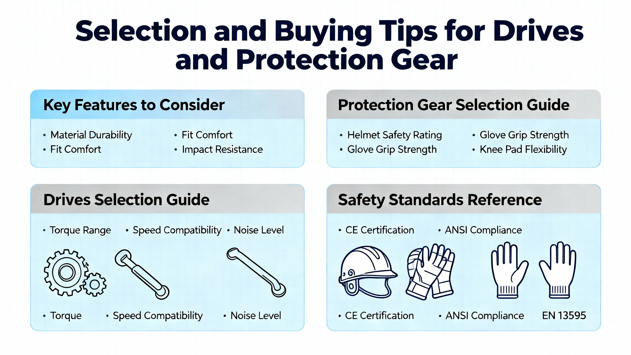
Selection and Buying Tips for Drives and Protection Gear
The best troubleshooting is the one you seldom need. Drive selection and power protection choices at purchase time harden your system against predictable disturbances. Size the driveŌĆÖs continuous current rating at or above the motor fullŌĆæload amperage and match its overload capacity to starting torque demands. Understand your duty rating: normal duty targets variableŌĆætorque loads such as pumps and fans, while heavy duty suits constantŌĆætorque jobs like conveyors, compressors, and presses. If the load has high inertia, plan for dynamic braking hardware and configure deceleration to avoid bus overvoltage. For installations with long motor leads or older motors, specify VFDŌĆærated shielded cable and consider output filters to tame reflected wave spikes and limit insulation stress. Select a drive family that supports event history with timestamps and a PC tool such as ABB Drive Composer to speed diagnostics and parameter management. Buy for the environment you actually have, including enclosure ratings and realistic airflow, because thermal margin is what keeps you from nuisance overtemperature trips on hot summer days. Round out the package with sound grounding and shielding practice and with power protection against surges, spikes, and brownouts to protect electronics at the heart of your operation.
Key Takeaway
Recovering an ABB drive from a fault is less about guesswork and more about a disciplined flow: read the exact code and event history, stabilize input power and terminations, commission the motor and control mode correctly, tune acceleration and braking to the load, and verify findings with instruments rated for VFD measurements. Use megohm testing to expose insulation weaknesses and address them before ground faults cascade into failure. When internal faults persist, move quickly to qualified bench testing and repair or replacement to protect uptime. Preventive care and thoughtful selectionŌĆöright duty rating, proper cabling and filtering, cooling, and robust diagnosticsŌĆöturn a reactive maintenance cycle into a controlled, lowŌĆærisk routine supported by solid reliability data.
FAQ
Why does my clamp meter show very low current while the drive display shows a high value?
Standard clamp meters often underŌĆæread on pulseŌĆæwidthŌĆæmodulated outputs. Use a trueŌĆæRMS, VFDŌĆærated meter and measure where it is valid, such as the input side and DC bus. Combine those readings with the driveŌĆÖs internal current display and event history to get the full picture.
How do I stop overvoltage trips when decelerating a highŌĆæinertia load?
Regenerative energy is pumping the DC bus above its limit. Extending the deceleration time and adding a properly sized dynamic braking resistor provides a safe path for that energy. Verify the braking parameters and wiring against the ABB manual, and then test under normal operating conditions.
My drive trips on overcurrent during start even after I checked the motor. What should I adjust first?
Review motor nameplate data, confirm the control mode, and lengthen the acceleration ramp to reduce inrush current during rampŌĆæup. If the load can be decoupled, confirm the shaft spins freely. For vector control, run a motor ID so the model matches the real motor.
When should I megger the motor and what values are acceptable?
Use a megohmmeter when groundŌĆæfault trips occur or after exposure to moisture or contaminants. Readings in the low megohm range, for example 2 to 20 megohms, indicate degraded insulation that needs attention. Below about 2 megohms is severe breakdown and the system should not be run. Replacement is generally advised when insulation resistance trends below roughly 10 megohms.
The drive loses my settings after power is cycled. How do I make changes stick?
Check the user access level and parameter lock state, then store changes to nonŌĆævolatile memory per the manual. Keep an offline parameter backup so you can restore quickly after resets or maintenance.
What is the difference between ABBŌĆÖs reliability tests, and why should I care?
Reliability Demonstration Testing confirms that a product survives a target life under accelerated stress without failing, while Accelerated Life Testing drives units to failure at various stress levels to estimate real life. ABB reports sample counts in the range of roughly seven to twenty for RDT and seven to sixty for ALT, with temperature cycling used to compress years of use into months. These methods help you compare vendors and choose equipment aligned with your uptime goals.
Sources
This guide draws on ABB drive manuals and application notes, ABB Drives highlights and references on reliability testing, Delta AutomationŌĆÖs drive troubleshooting practices, Joliet TechnologiesŌĆÖ discussion of typical VFD faults and mitigation, GES RepairŌĆÖs insulation testing guidance, practitioner experience documented on the Mike Holt forum, and repair workflow context from CM Industry Supply Automation.
References
- https://www.academia.edu/29203084/review_ABB_The_corporate_technical_journal
- https://www.ideals.illinois.edu/items/27900/bitstreams/93748/data.pdf
- https://dspace.mit.edu/bitstream/handle/1721.1/89280/46240185-MIT.pdf
- http://large.stanford.edu/courses/2022/ph240/tidd2/docs/abb-feb07.pdf
- https://digital.library.unt.edu/ark:/67531/metadc878646/m2/1/high_res_d/918445.pdf
- https://upcommons.upc.edu/server/api/core/bitstreams/a847e23f-5f20-40b9-9ffb-aa73d051a898/content
- https://do-server1.sfs.uwm.edu/slug/5539K3Z525/ref/8701K2Z/abb__s4-user_manual.pdf
- https://www.plctalk.net/forums/threads/variable-frequency-drive-from-abb-small-problem.20826/
- https://cmindustrysupply.com/blogs/abb-drive-repair-the-ultimate-guide
- https://gesrepair.com/how-to-identify-and-repair-insulation-breakdowns-in-abb-drives/


 Videos
 News
News Applications


Leave Your Comment