Why Your ABB Drive Is Really Tripping on ŌĆ£OverloadŌĆØ
When an ABB drive throws an overload or overcurrent type fault, it is not the drive being ŌĆ£too sensitive.ŌĆØ It is the drive doing exactly what it was designed to do: protect its power electronics and the motor before something burns. In the field, I often see maintenance teams jump straight to ŌĆ£turn the overload upŌĆØ or even attempt to reŌĆærate the drive in software. That might buy a little production time, but it usually shifts the risk from nuisance trips to smoked motors and failed IGBTs.
The good news is that ABB drives and ABB motor protection relays give you a lot of control over how overload is detected and when the drive trips. The key is to tune those motor protection settings so they reflect reality: the actual motor, the real load, and the real environment the drive lives in.
This article walks through how overload protection works in ABB drives, how to separate real overload from configuration or mechanical issues, and how to adjust motor protection settings in a controlled, reliabilityŌĆæfocused way. The discussion draws on manufacturer guidance from ABB technical literature, a detailed drive overload article from Joliet Technologies, ABB REM615 motor protection relay documentation, and practical troubleshooting experience shared in engineering forums.
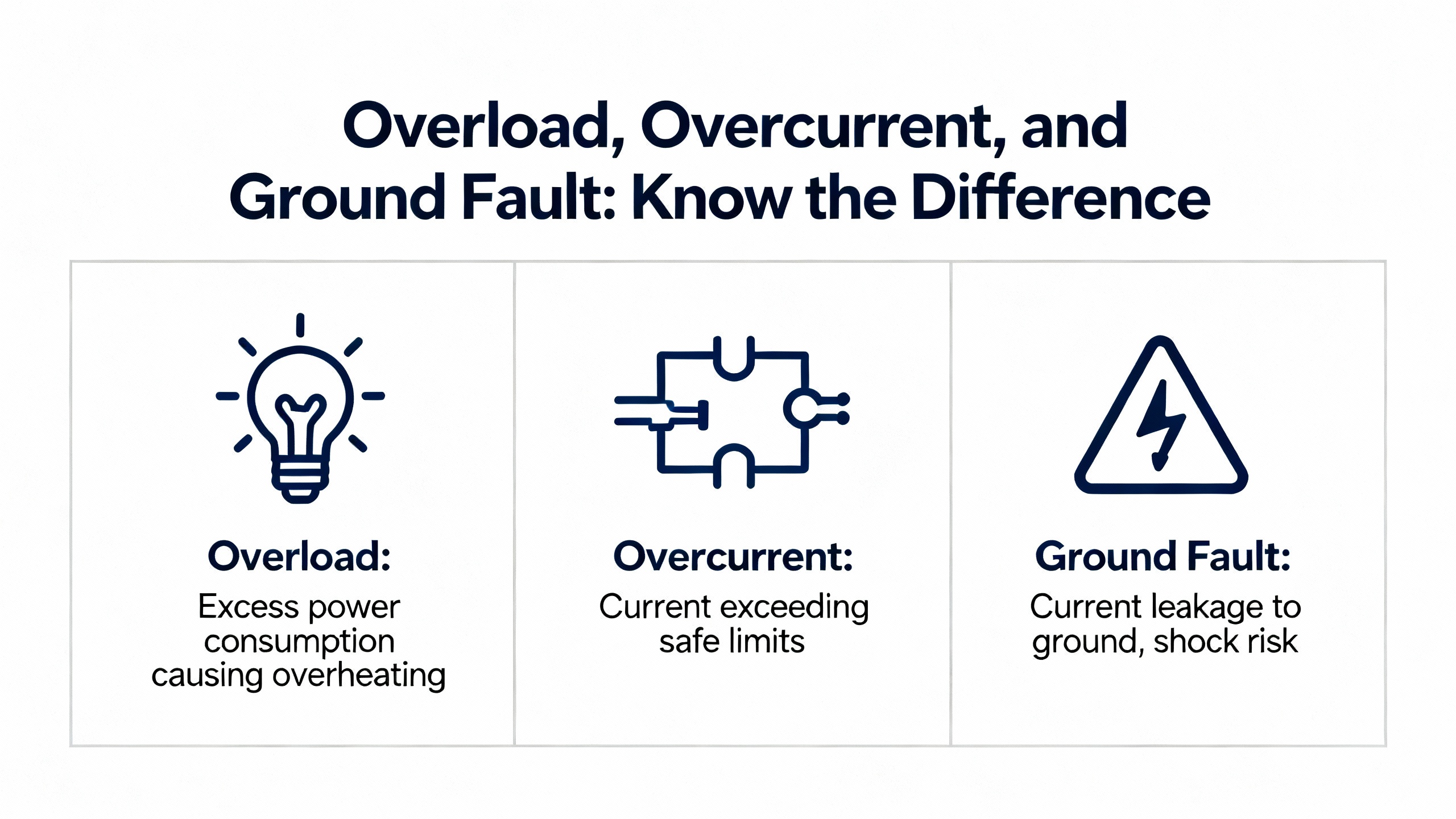
Overload, Overcurrent, and Ground Fault: Know the Difference
Before touching parameters, it helps to be precise about what kind of protection is acting. In drive and motor protection language, several concepts overlap but are not the same.
A motor overload condition means the motor is drawing more than its nameplate fullŌĆæload current for longer than it can thermally tolerate. ABBŌĆÖs REM615 relay documentation describes thermal overload protection as a model of motor heating based on measured current that trips when thermal ŌĆ£contentŌĆØ reaches one hundred percent. Drives implement similar thermal models internally. Overloads are often the result of heavy mechanical loading, high ambient temperature, or poor cooling.
A drive overcurrent fault is the drive saying: ŌĆ£Output current just exceeded my protection threshold.ŌĆØ As summarized in a general technical brief on VFD overcurrent and motor overload, drives typically allow shortŌĆæterm overcurrent, on the order of roughly one hundred ten to one hundred fifty percent of rated output current, for a few seconds up to around one minute, depending on the overload class. If that current stays too high or spikes far above the limit, the drive trips on overcurrent to protect its power section.
A drive overload fault is a timeŌĆæbased protection derived from current. Joliet Technologies describes a typical ŌĆ£normal dutyŌĆØ drive rating as allowing approximately one hundred twenty percent of rated output current for sixty seconds. The drive continuously compares measured current to its overload curve; exceed the permitted combination of current and time and you see an overload trip.
Ground faults are different again. In the ABB ACS510 community discussion, practitioners note that if the drive trips immediately at start, a ground fault or insulation problem is much more likely than a simple overload. That is consistent with the way nonŌĆædirectional earthŌĆæfault functions are described in ABBŌĆÖs REM615 material: they monitor residual current and operate as soon as that residual exceeds a set limit.
In practice, the first task is to identify which of these protections has acted. If you only have a generic alarm on a PLC screen, you are flying blind.
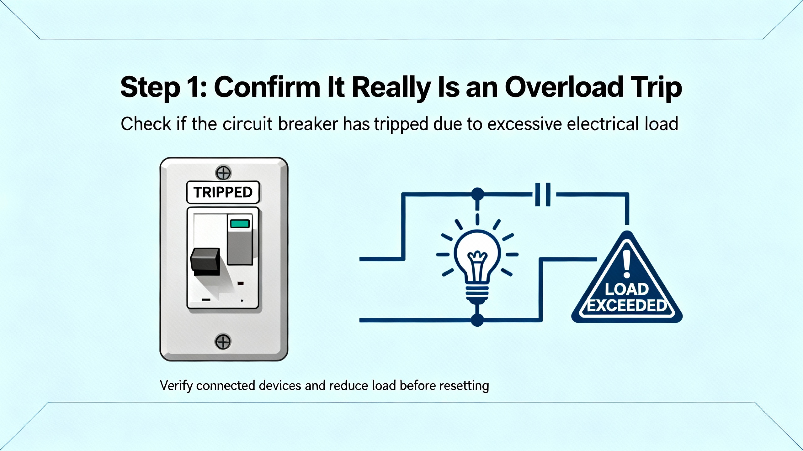
Step 1: Confirm It Really Is an Overload Trip
Read the Drive, Not Just the PLC
In several ABB drive installations I have been called to, the PLC or HMI simply reported ŌĆ£Drive faultŌĆØ or some generic code, while the drive itself had a detailed fault history. The ACS510 forum thread highlights the same concern: not all drive faults were mapped to the PLC, so technicians missed critical clues.
Whenever you see what looks like ŌĆ£overload,ŌĆØ go to the ABB drive keypad or to ABBŌĆÖs configuration tools and check the actual fault code and time stamp. ABB provides PC tools such as DriveConfig for low voltage drives, and more general IED engineering tools like PCM600 for protection relays. These tools let you read fault logs, view event histories, and see exactly which protection tripped and under what operating point.
If you are working with an external motor protection relay such as REM615 feeding the motor that your ABB drive controls, check that relayŌĆÖs disturbance records as well. REM615 is specifically designed to record which protection function operated (thermal overload, overcurrent, earth fault, phase reversal, loss of load, and so on) and at what current and time. That information is invaluable when deciding which settings to adjust.
Use Trip Timing as a Clue
The ACS510 troubleshooting discussion makes an important observation that matches field practice. If the drive trips a short time after starting, not instantly, an overload on the motor or mechanical load is a likely cause. That is consistent with a thermal or overload curve. Current is high during starting and then declines, but if torque demand stays too high, the overload curve is exceeded after a delay.
In contrast, if the drive trips essentially instantly at start, ground fault or serious shortŌĆæcircuit behavior is more probable. REM615 literature describes earthŌĆæfault and overcurrent elements that start timers as soon as their thresholds are exceeded; in severe faults the operate times are very short. You do not ŌĆ£fixŌĆØ that with an overload setting; you fix it by finding the fault.
Pay attention to the drive runtime when the fault occurs. An overload trip that appears after tens of seconds of heavy starting, or during a viscosity change in a mixer, is a different problem from an overcurrent trip the instant you energize the motor.
Rule Out Mechanical Problems Early
An ElectricianTalk discussion on ABB ACS800 overcurrent issues emphasizes not to ignore mechanical causes. Failing or overheated motor bearings, jammed mechanisms, or misalignment can all push current high enough to trip a drive and then ŌĆ£look fineŌĆØ after a coolŌĆædown when someone checks the machine.
In that case, current is a symptom, not the root cause. Checking lubrication, feeling for heat or vibration, verifying that nothing is running dry, and manually rotating the shaft where safe are basic steps. The same forum thread suggests a simple test when two drives are available: swap which drive feeds the motor. If the motor still trips when powered from the other drive, the problem is likely in the motor or mechanical load, not in the original drive settings.
If you adjust overload settings without addressing a mechanical bind, you are asking the drive to tolerate abuse. The next step is to confirm the electrical side and sizing.
Step 2: Verify Drive Sizing and Motor Data
Make Sure the Drive Is Big Enough for the Job
Joliet Technologies stresses that a key preŌĆætroubleshooting step for frequent overloads is to confirm that the drive is properly rated for the application. The driveŌĆÖs rated output current must at least match the motor nameplate fullŌĆæload amperes. Beyond that, you must consider the load profile.
Manufacturers typically publish dual ratings. Joliet gives an example of a threeŌĆæphase, 480 V drive that is rated at roughly twenty five horsepower and thirty eight amperes for variableŌĆætorque loads, but only about twenty horsepower and thirty one amperes for constantŌĆætorque or constantŌĆæhorsepower loads. The same hardware is capable of both, but the heavyŌĆæduty rating uses a lower continuous current to allow higher starting currents and more demanding torque profiles without overheating.
VariableŌĆætorque loads, like centrifugal fans and pumps, require relatively low torque at low speed and more torque as speed rises. ConstantŌĆætorque or constantŌĆæhorsepower loads, such as mixers and many conveyors, require high torque right from standstill. For these, ŌĆ£heavy dutyŌĆØ drive ratings apply.
In one sizing example, Joliet describes a mixer motor drawing thirty seven amperes at 460 V. Even though a smaller ŌĆ£normal dutyŌĆØ drive had a nameplate amp rating above thirty seven amperes, the recommendation was to choose the next size up heavyŌĆæduty unit, because during frequent heavy starts the smaller driveŌĆÖs power section would heat more and be prone to overload trips. The same principle applies to ABB drives. If an ABB drive feeding a constantŌĆætorque agitator regularly trips on overload at start, it may simply be undersized for heavy duty.
Beware of Software ŌĆ£ReŌĆæRatingŌĆØ Tricks
A detailed guide on ABB ACS510, ACS550, ACS350, ACS355, and ACH550 drives explains how to access extended parameter groups and adjust internal rated power and current values on the SMIOŌĆæ01C mainboard. By entering specific hexadecimal codes in parameters such as 105.09, and then using companion parameters to commit the change, the drive can be made to identify itself as a different current rating.
This procedure exists so that one control board can be reused across different drive sizes and to restore the correct rating if a control board is replaced. The same guide explicitly warns that this does not change the physical capacity of the power board. The true maximum output current and safe operating limits remain fixed by the hardware. If you set a software rating higher than what is printed on the drive label, you can easily exceed the design thermal margin of the power section.
In a reliabilityŌĆæfocused troubleshooting effort, the right use of this capability is to verify that the software rating matches the physical rating after any board swap or repair. It is not a legitimate way to solve overload trips by pretending the drive is larger than it is.
Enter Motor Nameplate Data Correctly
Control EngineeringŌĆÖs discussion of key VFD parameter changes, along with ABB ACS880 parameter setting guides shared among commissioning engineers, all emphasize the same basic point: accurate motor nameplate data must be entered into the drive. This includes rated voltage, frequency, fullŌĆæload current, speed, and power.
The driveŌĆÖs internal motor model, its thermal overload calculation, and advanced control modes all depend on this data. If the drive ŌĆ£thinksŌĆØ the motor is smaller than it really is, the electronic overload may trip early. If it thinks the motor is larger than it is, you risk overheating the motor before the drive trips.
From a motor protection standpoint, getting these basic parameters correct is the foundation. Only after motor data and sizing are correct does it make sense to fineŌĆætune overload settings.
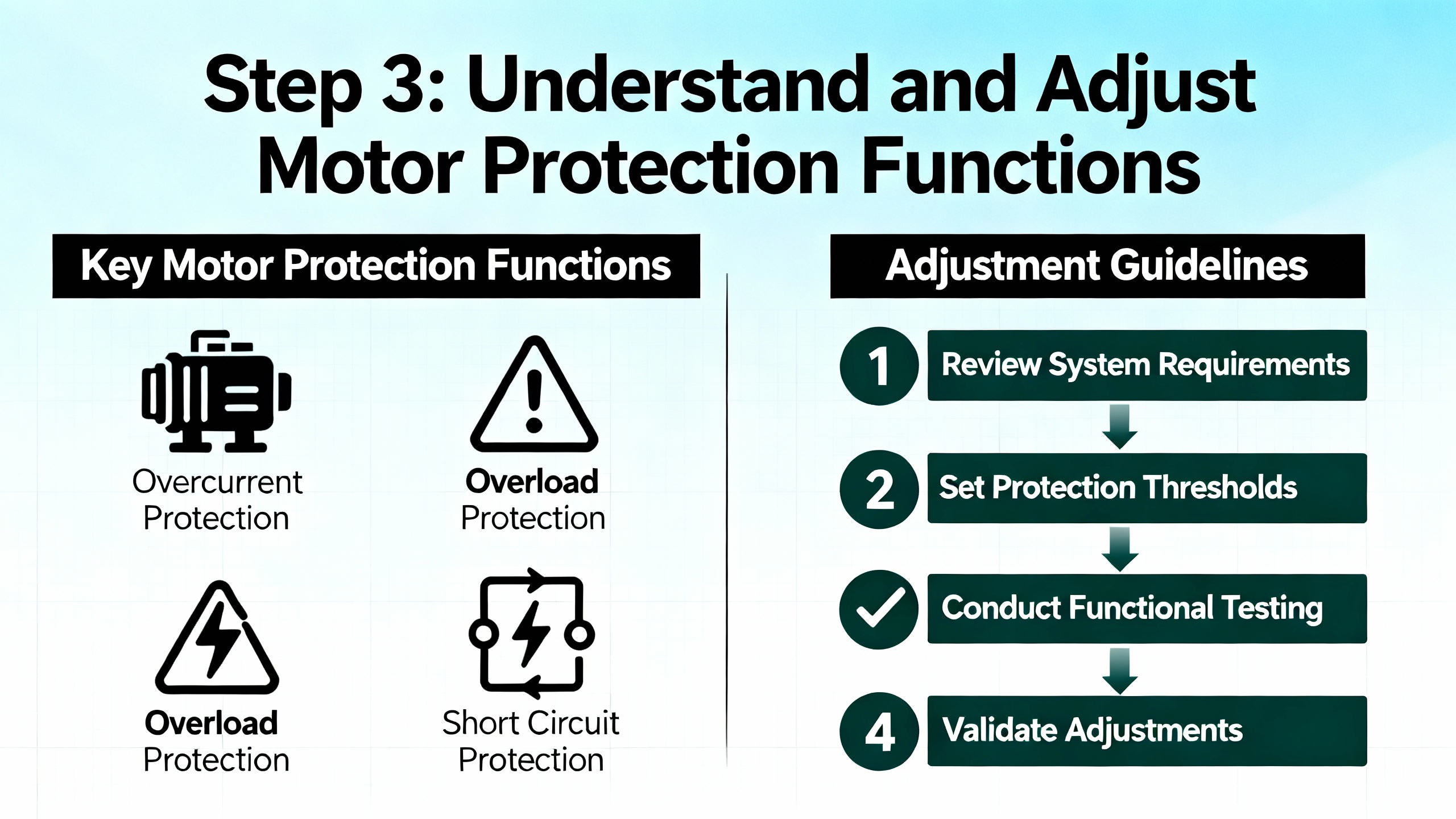
Step 3: Understand and Adjust Motor Protection Functions
Whether motor protection is implemented inside the ABB drive or in a separate ABB relay like REM615, the underlying concepts are similar. The protection functions look at current, time, phase relationships, and sometimes torque or power to decide when to trip. The goal is to protect the motor without constantly stopping the process for spurious reasons.
Thermal Overload Modeling
ABBŌĆÖs REM615 documentation describes a threeŌĆæphase thermal overload function that models motor heating using measured current and trips when the thermal state reaches one hundred percent. It is intended to handle both shortŌĆæterm and longŌĆæterm overloads under varying load conditions and to limit the motor thermal level to predetermined values during abnormal operation. The abnormal conditions listed include overload, stalling, failure to start, high ambient temperature, restricted ventilation, reduced speed operation, frequent starting, mechanical failure, improper installation, and voltage imbalance.
ABB drives implement an electronic thermal overload in a similar spirit. The drive continuously integrates motor current over time against the programmed overload curve. If the thermal model says the motor has reached its allowable limit, the drive trips, often with an overload code rather than a hard overcurrent fault.
From a settings perspective, this means that shortening acceleration time, increasing allowed overload current, or changing drive duty class all distort that thermal model. For example, if you ask for very aggressive acceleration on a highŌĆæinertia fan, you may hit the overload curve before the fan reaches speed, even if the drive and motor are nominally correctly sized. JolietŌĆÖs article notes that largeŌĆædiameter fans often need slower acceleration and deceleration ramps purely to stay within the driveŌĆÖs overload capabilities.
When tuning motor protection, it is better to begin by matching the thermal overload model to the motor manufacturerŌĆÖs data and the load type, then adjust process settings such as accel and decel to work within that envelope.
Overcurrent and Overload Limits
Overcurrent elements in ABB protection devices are usually configurable as definite time or inverse definite minimum time. The REM615 description of threeŌĆæphase nonŌĆædirectional overcurrent protection explains that phase currents are compared to a start value; if they exceed that value in the required number of phases, a timer is started. Depending on the chosen curve, the operate time is constant or inversely proportional to how far above the pickup current you are.
Drives use similar logic internally. The general VFD overcurrent and motor overload guidance in the PrecisionŌĆæElec brief notes that when output current exceeds the driveŌĆÖs programmed limit, the drive interprets this as an overcurrent or overload condition and trips. Typical overload capability allows limited overcurrent above rated amps for a specified time.
Before increasing any drive limit, verify that measured current at actual load is reasonable relative to the motor nameplate. If a machine draws close to or above fullŌĆæload current during normal production, you may have a mechanical issue or an undersized motor, not an overly conservative drive. Increasing overcurrent limits or overload thresholds in such a case simply hides the symptom.
StartŌĆæUp Supervision and Locked Rotor
REM615 includes a specific motor startŌĆæup supervision function that protects against excessive starting time and lockedŌĆærotor conditions. It supervises motor start by monitoring RMS phase currents or breaker status and ensures that thermal stress during start remains within allowed limits.
ABB drives provide equivalent protection, usually through startŌĆæup monitoring and stall detection features. In practice, if a motor start takes too long because of process conditions, current stays high, the thermal model climbs rapidly, and the drive will eventually trip on overload or stall.
There are two levers here. One is process and mechanics: do you really need to start under full load, or can you unload at start, then ramp the process load in? The other is tuning the allowed start time, accel ramp, and stall detection level so that a healthy start is not mistaken for a locked rotor, while a genuine locked rotor is caught quickly.
Custom Load Curves and Advanced Detection
Modern ABB drives, such as the ACS880 series described by Joliet Technologies, can go beyond simple current and time checks. They can implement userŌĆædefined load curves that compare measured torque or current against speed or frequency across several userŌĆæselected operating points. High and low thresholds around each point define zones of acceptable operation.
With such a curve, you can program the drive to alarm or trip if the motor draws more current than expected at a particular speed, which is a powerful way to detect conditions like a clogged pump or jammed auger. Delay times let you avoid tripping on transient spikes while still reacting to sustained abnormal load.
The advantage of this approach is that it tailors overload detection to the process, not just to the motor. The tradeŌĆæoff is complexity: if curves and thresholds are not carefully chosen, you can get repeated nuisance trips that offer little real protection.
Coordinating With External Protection Relays
In many industrial systems, the ABB drive is not the only protection device. A relay such as REM615 may provide overcurrent, earthŌĆæfault, thermal overload, phase reversal, and lossŌĆæofŌĆæload functions upstream. For example, REM615ŌĆÖs lossŌĆæofŌĆæload function detects a sudden drop in current that indicates an unexpected load loss, while its phaseŌĆæreversal function uses negativeŌĆæsequence current to detect reversed phase order causing reverse rotation.
When both the drive and the relay monitor similar quantities, coordination becomes essential. If the relayŌĆÖs thermal overload curve is more sensitive than the driveŌĆÖs, it will always trip first and the driveŌĆÖs own overload settings become largely academic. Conversely, if you loosen the relay but tighten the drive, the drive will always trip first.
A reliabilityŌĆæoriented approach is to let the device closest to the motor current do the thermal protection, often the drive, while the upstream relay focuses on faults like overcurrent, earth faults, and backup overload. Coordination curves in ABBŌĆÖs technical guidebooks and relay manuals provide a good starting point for this.
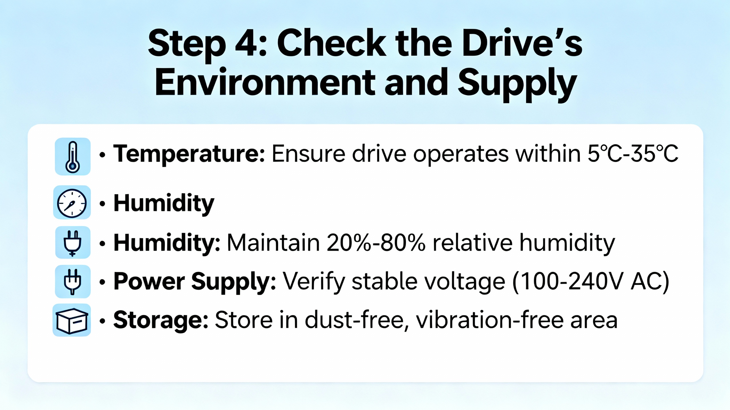
Step 4: Check the DriveŌĆÖs Environment and Supply
Even perfectly tuned motor protection will not behave well if the drive is being cooked in a hot, dirty enclosure or starved by a weak power supply. Several of the research sources highlight how frequently overload trips are symptoms of environmental or supply problems.
Heat, Enclosures, and Cooling
Joliet Technologies points out that most drives can operate at full rating up to about 104┬░F at their heatsinks, and can run at reduced output up to roughly 122┬░F. Those temperatures include both the ambient air and the heat the drive itself generates.
A drive of about thirty horsepower can dissipate on the order of five hundred watts of heat into its enclosure, given typical loss figures of roughly two to three percent of kilowatt output. In a closed cabinet sitting in 90┬░F air, especially outdoors in direct sun, internal temperatures can climb quickly unless cooling is carefully designed.
If filters on cooling fans are clogged, if the refrigerant system serving the enclosure is not working, or if liquid cooling circuits on large drives are not circulating coolant at the correct temperature, internal temperature rise will be faster. In an ABB ACS510 troubleshooting thread, users specifically ask whether high drive temperature alone can cause sudden tripping, and the answer is yes: thermal protection will act to prevent electronics damage.
Whenever overload or overtemperature trips appear, inspect the enclosure and cooling hardware. Check for blocked filters, failed fans, missing or damaged sunshades, and dust buildup. An overload that coincides with seasonal temperature rises is often a cooling problem in disguise.
Supply Voltage, Frequency, and Long Motor Leads
JolietŌĆÖs article notes that even a five percent sag in supply voltage can be significant. If incoming voltage is already five percent below nominal and then sags an additional five percent under load, the drive may be effectively operating ten percent low. To deliver the same mechanical power, the motor draws more current, pushing the drive closer to its overload limits.
In the ACS510 community discussion, one of the first recommendations is to verify that incoming supply frequency matches the drive configuration. If the drive is set for one nominal frequency but the power system delivers another, performance issues and unexpected trips are likely.
The ElectricianTalk conversation about ABB ACS800 overcurrent faults raises another subtle point: very long distances between drive and motor. Long motor cables add impedance, can create substantial voltage drop, and can introduce reflections that stress the driveŌĆÖs output stage. The commenter notes that they would normally install such a drive closer to the motor and, with long leads, use a load reactor on the drive output. While that particular case did not definitively blame the missing reactor, it is a common mitigation.
From a motor protection perspective, poor voltage quality or long cables can make the drive ŌĆ£seeŌĆØ higher current for a given mechanical load. Addressing those power quality issues often reduces apparent overload problems.
Automatic Restart and Safety
Forum contributors comparing ABB drives to Schneider Altivar mention parameters that allow a drive to automatically restart after a power failure if a run command is present. ABB drives have similar autoŌĆærestart capabilities. These functions can help recover a process after brief outages, but they are inherently hazardous because the motor can start unexpectedly when power returns.
When you adjust motor protection thresholds, especially overload and stall detection, remember that autoŌĆærestart can cause the drive to repeatedly attempt to start into a faulted or jammed load. That is hard on both the drive and the motor and can create serious safety risks for personnel. Automatic restart should be enabled only under strict risk assessment and with safeguards that prevent unexpected motion in unsafe conditions.
Step 5: Adjusting Settings and Testing in a Controlled Way
Once you have verified that the motor and drive are correctly sized, checked mechanical health, confirmed motor data, and inspected the environment and supply, you are ready to fineŌĆætune protection settings. The process should be deliberate and documented.
Use the DriveŌĆÖs Commissioning Tools
ABB ACS880 drives and many other ABB models provide an assistant control panel that walks you through parameter setting step by step. Commissioning guides circulated among ACS880 users stress grouping settings into primary, secondary, and macro parameters to keep things manageable and to focus first on what matters most: motor data, control mode, speed reference, and protection parameters.
For driveŌĆæintegrated overload settings, start by confirming that the selected duty class or overload curve matches the application. Then review acceleration and deceleration times against the actual mechanical inertia. For highŌĆæinertia fans and similar loads, lengthening accel and decel is often more effective and safer than raising current limits.
If you are working with REM615 or another ABB relay for motor protection, use PCM600 to read the existing configuration, including overcurrent and thermal settings. The REM615 material stresses the importance of understanding the current transformers, start values, timing curves, and reset behavior (such as the two hundred millisecond reset timer in certain functions).
Follow a StepŌĆæByŌĆæStep Test Strategy
A LinkedIn troubleshooting guide for ABB ACS880 drives recommends a systematic approach: verify basic hardware first, then motor configuration, then communication, and so on, while using the driveŌĆÖs diagnostic tools and official manuals to interpret codes. That same discipline applies to testing new protection settings.
Begin with noŌĆæload or lightŌĆæload tests. Command the motor to start, observe current, acceleration time, and any early warnings, and confirm that measured current is consistent with expectations. Then progress to normal process load while monitoring drive current, motor temperature, and fault counters.
Where possible, use logged data rather than snapshots. Many ABB drives and ABB protection relays allow you to view trend or waveform records around a trip. Those records give you a thermal and current history to compare against your settings.
Document every parameter change and keep a copy of the original configuration. Control EngineeringŌĆÖs discussion of VFD parameter management recommends backing up drive configurations, standardizing parameter sets across similar machines where appropriate, and securing access to prevent unauthorized edits. That advice applies directly when you adjust overload and protection settings.
What Success Looks Like
After tuning, a healthy system will start within the expected time, reach target speed without hitting overcurrent or overload limits, and run at normal load with current reasonably below fullŌĆæload amps. Occasional transient warnings or brief operation in a highŌĆæoverload region during start may be acceptable, as long as the thermal model has time to cool between starts.
If the drive still trips on overload in normal operation after careful tuning and environmental checks, you are likely looking at a genuine undersizing problem or a motor that is working harder than it was originally designed to do. In such cases, increasing motor size or drive size, or reducing process demand, is a more reliable solution than further relaxing protection.
Quick Reference: Fault Type vs Likely Cause
The following table summarizes how different protection trips typically relate to root causes, based on ABB protection descriptions, Joliet TechnologiesŌĆÖ overload analysis, and field discussions around ABB drives.
| Fault indication | What the drive or relay ŌĆ£seesŌĆØ | Typical underlying issues |
| Overload / thermal trip | Current above rated value long enough to heat the motor | High mechanical load, frequent starts, high ambient, poor cooling, undersized drive or motor |
| Overcurrent fault | Current abruptly above protection limit | Mechanical jam, starting too hard, shorted turns, severe voltage issues |
| Ground / earth fault | Significant residual current | Insulation failure, wiring fault to ground, damaged cable |
| Stall / locked rotor | High current, little or no speed change | Jammed load, failed coupling, mechanical seizure |
| Loss of load | Current suddenly dropping below expected range | Broken shaft, pump running dry, disconnected load |
This table is not a substitute for the exact ABB fault code descriptions in the official manuals, but it gives a practical mental model for where to look before you touch overload settings.
FAQ
How much can I safely increase ABB drive overload settings?
There is no universal ŌĆ£safeŌĆØ number you can dial in. Joliet Technologies notes that normal duty drives might allow around one hundred twenty percent of rated current for about sixty seconds, and general VFD guidance suggests that overload capability in the range of one hundred ten to one hundred fifty percent of rated current for short periods is typical. The exact limits are driveŌĆæspecific. Always consult the ABB user manual and never exceed the overload ratings defined there. If you are at or near those ratings and still tripping, the right answer is usually to address the load or sizing, not to increase the limit further.
Should I adjust software rated power to stop overload trips?
The procedure described for ABB ACS510, ACS550, ACS350, ACS355, and ACH550 drives that changes rated current and power in parameters on the SMIOŌĆæ01C board is meant to align software identification with actual hardware ratings. It does not increase the physical capability of the power stage. Using it to ŌĆ£upŌĆærateŌĆØ a smaller drive to behave like a larger one undermines the protective design and can easily lead to drive failure. Use that tool only to correct mismatches after board replacement and always set ratings to match the nameplate.
Can automatic restart help with overload issues?
Automatic restart functions on ABB drives can reduce downtime after brief power interruptions, but they do not solve the underlying cause of overload or overcurrent trips. As highlighted in comparisons with Schneider drives on user forums, autoŌĆærestart carries a real hazard: motors can start unexpectedly after power returns. If a drive is repeatedly tripping on overload because of a jam or misŌĆæsetting, autoŌĆærestart will simply produce repeated starts into a fault, which is worse for both equipment and safety. Fix the root cause first; use autoŌĆærestart only where the risk has been carefully assessed.
Closing
WellŌĆætuned motor protection on ABB drives is not about squeezing the last ampere out of the hardware; it is about matching protection to the real motor, the real load, and the real conditions in your plant. When you respect the physics behind overload curves, verify sizing and environment, and adjust settings with a clear test plan, overload trips stop being mysterious ŌĆ£drive problemsŌĆØ and become what they were meant to be: a precise early warning that keeps your motors and drives alive for the long run.
References
- https://www.academia.edu/39419031/MOTOR_PROTECTION_WITH_REM_615
- https://upcommons.upc.edu/bitstreams/a847e23f-5f20-40b9-9ffb-aa73d051a898/download
- https://irtfweb.ifa.hawaii.edu/~tcs3/tcs3/Misc/CFHT/Dome_drive_upgrade/ABB%20Proposal-for%20reference-not%20chosen/C--Work-ABB%20Drives-ACS800-Manuals-ACS800%20Tech%20Catalog.pdf
- https://seniordesign.engr.uidaho.edu/2012-2013/sel/documents/Documentation/ACS550-U1-031-2%20ASD%20User%27s%20Manual.pdf
- https://do-server1.sfs.uwm.edu/find/E7E5480507/pub/E3E3597/abb_acs-1000_manual.pdf
- https://www.longi.net/how-to-adjust-the-power-rating-of-abbs-acs510-acs550-acs350-acs355-ach550-vfds/?srsltid=AfmBOordHAQxSyAlT273pBj6LadkRe82evlzHXXPSnRj6If-uLDf8_BJ
- https://www.controleng.com/top-5-vfd-parameter-changes-explained/
- https://www.linkedin.com/pulse/abb-drive-acs880-troubleshooting-guide-electrical-md-rabiul-hossain-b6joc
- https://community.oxmaint.com/discussion-forum/troubleshooting-abb-acs510-inverter-issue-with-motor-load
- https://www.precision-elec.com/abb-acs355-training-lesson-6-advanced-drive-protective-fuse-sizing-motor-overload-setup/?srsltid=AfmBOopgF9gwExLfGgGi7Z5zPIKWyKgjSpMz6qaJJJzW3qB3961bWSBG


 Videos
 News
News Applications


Leave Your Comment