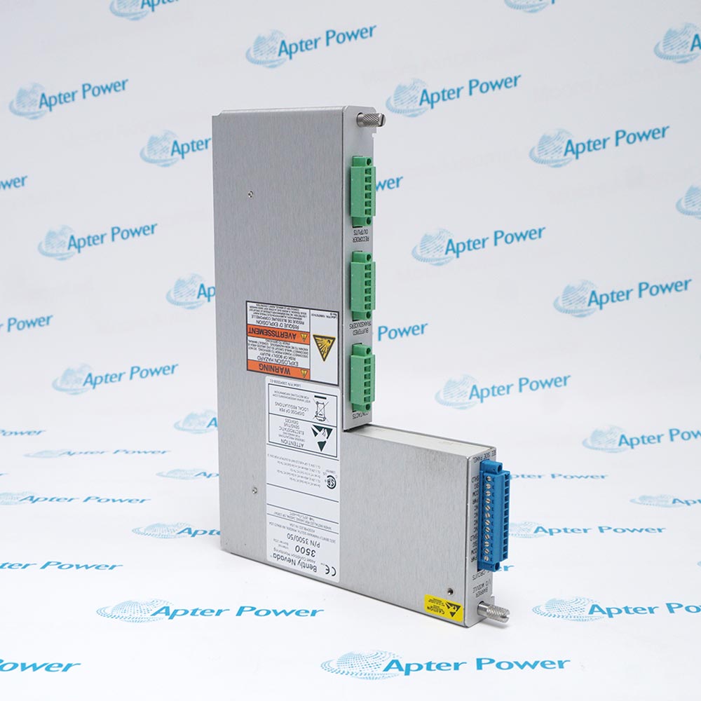
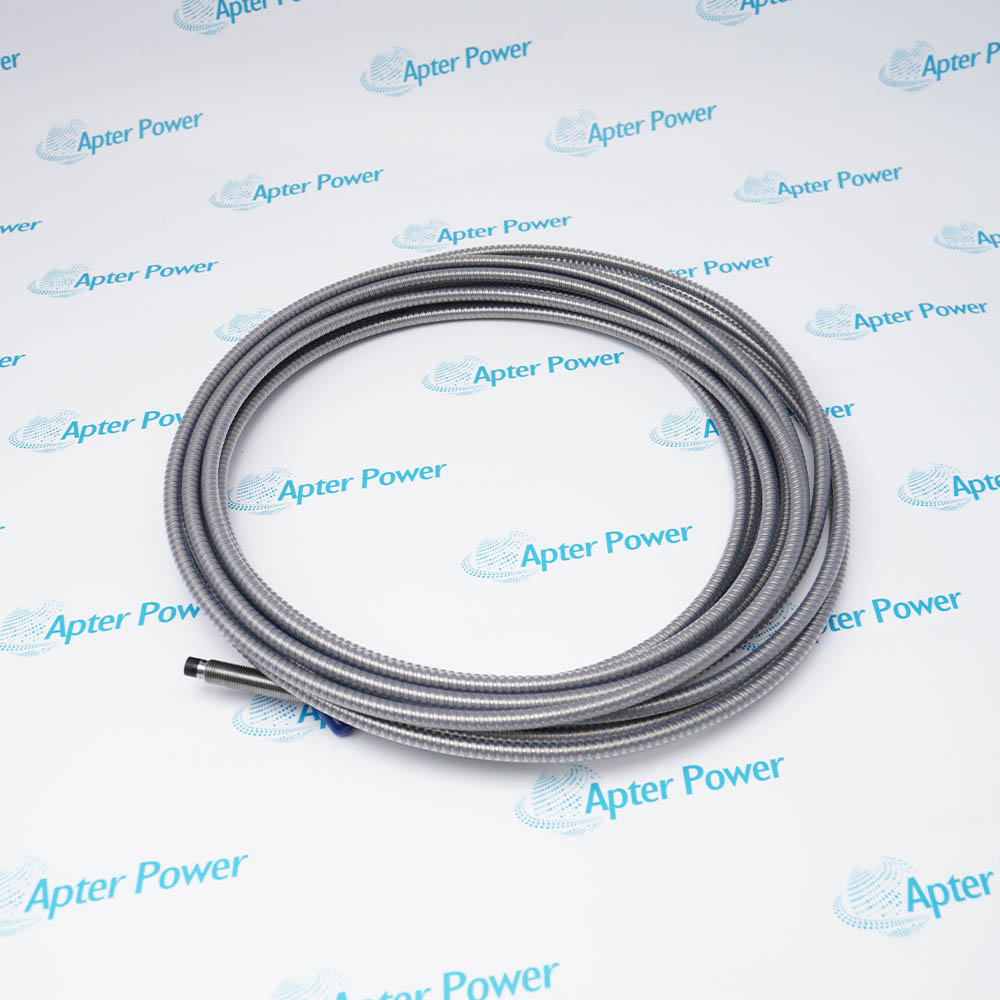
The 991-06-70-02-05 is a Bently Nevada 991 two-wire loop-powered thrust transmitter configured for a 0.6-0-0.6 mm full-scale axial-displacement range, a 7.0 m 3300 NSv transducer-system length, bulkhead-screw mounting, and CSA Division 2, ATEX Zone 0, ATEX Zone 2, and ABS maritime approvals.
- One 3300 NSv probe and matching extension cable
- +12 to +35 Vdc at transmitter terminal
- 4 to 20 mAdc, two-wire
- 0.6-0-0.6 mm
It accepts a 3300 NSv proximity probe and matching extension cable, conditions the shaft axial-position signal into a standard 4 to 20 mA output for a machinery control system, and provides non-isolated PROX OUT and COM diagnostic signals for gap voltage and dynamic vibration. It is intended primarily for centrifugal air compressors and small pumps, motors, or fans. For dependable operation, follow the official system-matching, mounting, wiring, environmental, and approval instructions.
Important Notice: This transmitter is not a full continuous-monitoring system. Verify probe gap, zero/span, 7 m matching, loop scaling, isolation, approvals, and the machinery protection strategy before commissioning.
Apter Power 991-06-70-02-05 Manuals and Guides
Important Notice: These are two separate Apter Power documents prepared from the official Bently Nevada source named in each document. Confirm the physical nameplate, current manufacturer documentation, and applicable installation drawing before installation or replacement.
Centrifugal Air Compressors
Feeds an axial-position signal to the compressor control system.
Small Pumps
Provides simple 4 to 20 mA thrust-position trending and alarm input.
Motors and Fans
Supports axial-position monitoring where the application limitations are accepted.
OEM Machinery Panels
Bulkhead mounting supports compact packaged-equipment control panels.
Maritime Machinery
Option 05 includes the manufacturer-listed ABS maritime approval.
Diagnostic Verification
PROX OUT supports isolated gap and dynamic-signal checks.
Read and follow the official manufacturer source and applicable installation instructions before use. Verify the exact complete ordering code from the physical nameplate.
1
Match the connected 3300 NSv probe and extension cable to the ordered 7.0 m system length.
2
Set probe gap, zero, and span according to the official thrust-transmitter procedure; incorrect gap can prevent full-scale output.
3
Use the 122115-01 Test Adapter when connecting grounded ac-powered equipment to PROX OUT because the diagnostic signal is non-isolated.
4
Verify loop supply, total resistance, polarity, shield termination, and control-system scaling before applying machinery protection logic.
5
Confirm the option 05 nameplate, entity parameters, barriers, maritime requirements, and current installation drawing before hazardous-area service.


 Videos
 News
News Applications